EP1536507A1 - Procede de conception d'un systeme de batterie redox a circulation constante - Google Patents
Procede de conception d'un systeme de batterie redox a circulation constante Download PDFInfo
- Publication number
- EP1536507A1 EP1536507A1 EP03717669A EP03717669A EP1536507A1 EP 1536507 A1 EP1536507 A1 EP 1536507A1 EP 03717669 A EP03717669 A EP 03717669A EP 03717669 A EP03717669 A EP 03717669A EP 1536507 A1 EP1536507 A1 EP 1536507A1
- Authority
- EP
- European Patent Office
- Prior art keywords
- output
- battery
- redox flow
- power generation
- ave
- Prior art date
- Legal status (The legal status is an assumption and is not a legal conclusion. Google has not performed a legal analysis and makes no representation as to the accuracy of the status listed.)
- Granted
Links
Images


Classifications
-
- H—ELECTRICITY
- H01—ELECTRIC ELEMENTS
- H01M—PROCESSES OR MEANS, e.g. BATTERIES, FOR THE DIRECT CONVERSION OF CHEMICAL ENERGY INTO ELECTRICAL ENERGY
- H01M8/00—Fuel cells; Manufacture thereof
- H01M8/18—Regenerative fuel cells, e.g. redox flow batteries or secondary fuel cells
- H01M8/184—Regeneration by electrochemical means
- H01M8/188—Regeneration by electrochemical means by recharging of redox couples containing fluids; Redox flow type batteries
-
- H—ELECTRICITY
- H01—ELECTRIC ELEMENTS
- H01M—PROCESSES OR MEANS, e.g. BATTERIES, FOR THE DIRECT CONVERSION OF CHEMICAL ENERGY INTO ELECTRICAL ENERGY
- H01M8/00—Fuel cells; Manufacture thereof
- H01M8/04—Auxiliary arrangements, e.g. for control of pressure or for circulation of fluids
- H01M8/04298—Processes for controlling fuel cells or fuel cell systems
- H01M8/04313—Processes for controlling fuel cells or fuel cell systems characterised by the detection or assessment of variables; characterised by the detection or assessment of failure or abnormal function
- H01M8/0432—Temperature; Ambient temperature
- H01M8/04328—Temperature; Ambient temperature of anode reactants at the inlet or inside the fuel cell
-
- H—ELECTRICITY
- H01—ELECTRIC ELEMENTS
- H01M—PROCESSES OR MEANS, e.g. BATTERIES, FOR THE DIRECT CONVERSION OF CHEMICAL ENERGY INTO ELECTRICAL ENERGY
- H01M8/00—Fuel cells; Manufacture thereof
- H01M8/04—Auxiliary arrangements, e.g. for control of pressure or for circulation of fluids
- H01M8/04298—Processes for controlling fuel cells or fuel cell systems
- H01M8/04313—Processes for controlling fuel cells or fuel cell systems characterised by the detection or assessment of variables; characterised by the detection or assessment of failure or abnormal function
- H01M8/0432—Temperature; Ambient temperature
- H01M8/04335—Temperature; Ambient temperature of cathode reactants at the inlet or inside the fuel cell
-
- H—ELECTRICITY
- H01—ELECTRIC ELEMENTS
- H01M—PROCESSES OR MEANS, e.g. BATTERIES, FOR THE DIRECT CONVERSION OF CHEMICAL ENERGY INTO ELECTRICAL ENERGY
- H01M8/00—Fuel cells; Manufacture thereof
- H01M8/04—Auxiliary arrangements, e.g. for control of pressure or for circulation of fluids
- H01M8/04298—Processes for controlling fuel cells or fuel cell systems
- H01M8/04313—Processes for controlling fuel cells or fuel cell systems characterised by the detection or assessment of variables; characterised by the detection or assessment of failure or abnormal function
- H01M8/0438—Pressure; Ambient pressure; Flow
- H01M8/04388—Pressure; Ambient pressure; Flow of anode reactants at the inlet or inside the fuel cell
-
- H—ELECTRICITY
- H01—ELECTRIC ELEMENTS
- H01M—PROCESSES OR MEANS, e.g. BATTERIES, FOR THE DIRECT CONVERSION OF CHEMICAL ENERGY INTO ELECTRICAL ENERGY
- H01M8/00—Fuel cells; Manufacture thereof
- H01M8/04—Auxiliary arrangements, e.g. for control of pressure or for circulation of fluids
- H01M8/04298—Processes for controlling fuel cells or fuel cell systems
- H01M8/04313—Processes for controlling fuel cells or fuel cell systems characterised by the detection or assessment of variables; characterised by the detection or assessment of failure or abnormal function
- H01M8/0438—Pressure; Ambient pressure; Flow
- H01M8/04395—Pressure; Ambient pressure; Flow of cathode reactants at the inlet or inside the fuel cell
-
- H—ELECTRICITY
- H01—ELECTRIC ELEMENTS
- H01M—PROCESSES OR MEANS, e.g. BATTERIES, FOR THE DIRECT CONVERSION OF CHEMICAL ENERGY INTO ELECTRICAL ENERGY
- H01M8/00—Fuel cells; Manufacture thereof
- H01M8/04—Auxiliary arrangements, e.g. for control of pressure or for circulation of fluids
- H01M8/04298—Processes for controlling fuel cells or fuel cell systems
- H01M8/04313—Processes for controlling fuel cells or fuel cell systems characterised by the detection or assessment of variables; characterised by the detection or assessment of failure or abnormal function
- H01M8/04537—Electric variables
- H01M8/04604—Power, energy, capacity or load
- H01M8/04626—Power, energy, capacity or load of auxiliary devices, e.g. batteries, capacitors
-
- Y—GENERAL TAGGING OF NEW TECHNOLOGICAL DEVELOPMENTS; GENERAL TAGGING OF CROSS-SECTIONAL TECHNOLOGIES SPANNING OVER SEVERAL SECTIONS OF THE IPC; TECHNICAL SUBJECTS COVERED BY FORMER USPC CROSS-REFERENCE ART COLLECTIONS [XRACs] AND DIGESTS
- Y02—TECHNOLOGIES OR APPLICATIONS FOR MITIGATION OR ADAPTATION AGAINST CLIMATE CHANGE
- Y02E—REDUCTION OF GREENHOUSE GAS [GHG] EMISSIONS, RELATED TO ENERGY GENERATION, TRANSMISSION OR DISTRIBUTION
- Y02E60/00—Enabling technologies; Technologies with a potential or indirect contribution to GHG emissions mitigation
- Y02E60/30—Hydrogen technology
- Y02E60/50—Fuel cells
Definitions
- the present invention relates to a method of designing a redox flow battery system including a redox flow battery to force electrolytic solution to be fed to and discharged from its cells.
- the present invention relates to a method of designing a redox flow battery system that can reduce a battery system loss.
- This publication describes that a lead storage battery, which does not need any moving parts, such as a pump and the like, is further annexed to the redox flow battery, in order to reduce a pump power loss and a loss caused by a shunt current, which contributes to reduction of combined efficiency of the redox flow battery, in response to input power.
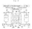
- FIG. 8 shows an explanatory view showing an operating principle of a general redox flow secondary battery.
- This battery has a cell 100 which is separated into a positive electrode cell 100A and a negative electrode cell 100B by a membrane 103 of an ion-exchange membrane.
- a positive electrode 104 and a negative electrode 105 are contained in the positive electrode cell 100A and the negative electrode cell 100B, respectively.
- a positive electrode tank 101 for feeding and discharging positive electrolytic solution to and from the positive electrode cell 100A is connected to the positive electrode cell 100A through conduit pipes 106, 107.
- a negative electrode tank 102 for feeding and discharging negative electrolytic solution to and from the negative electrode cell 100B is connected to the negative electrode cell 100B through conduit pipes 109, 110.
- Aqueous solution containing ions that change in valence, such as vanadium ion, is used for the respective electrolytes and is circulated by using pumps 108, 111, to charge or discharge with an ionic valence change reaction at the positive and negative electrodes 104, 105.
- the annex of the lead storage battery for the purpose of improving reduction of efficiency caused by weak power generation or load power at the time of electric charge or discharge or preventing increase of a system loss at the time of electric charge or discharge, as in the technique disclosed in the publication above, causes the problems of not only increase in production costs but also increase in scale of facilities.
- a system loss means a total of a battery loss and a converter loss.
- the technique described in the publication cited above takes a pump power loss and a shunt current loss into consideration as factors of the battery loss, but takes no thought of an efficiency loss caused by a battery resistance (cell resistance). In view of this, the system that can provide further reduced loss is being desired.
- the redox flow battery is practically operated, combining with the storage battery of a reasonable magnitude, or specifically, a magnitude of output about one half the total output of power generation, but this operation induces a great system loss, leading to deterioration of system efficiency.
- the present invention is defined on the basis of the knowledge given below.
- the present invention is directed to a novel method of designing a redox flow battery system comprising a redox flow battery to force electrolytic solution to be fed to and discharged from its cells, comprising the steps of: first, determining an external parameter given by an operating condition of the redox flow battery a designer cannot choose voluntarily; then, determining an internal parameter given by a design condition of the redox flow battery the designer can design voluntarily; then, determining an average value of variables of the external parameter and standard deviation; and determining an optimum value of the internal parameter based on at least either of the resulting average value and the resulting standard deviation.
- the inventors After having studied the possibilities of improvement from various angles, the inventors have found that the characteristics of the battery system above (reduction in system loss) can be optimized by determining magnitudes (specified output, number of cells, etc.) of the redox flow battery, magnitudes (specified output, etc.) of the DC/AC converter, such as an inverter, and other operating conditions (flow rate of electrolyte for each cell, temperature of electrolyte, etc.) by the specified method mentioned above, leading to the accomplishment of the present invention. In the following, the present invention will be explained in further detail.
- the external parameter is defined here as a parameter given by the operating condition of the redox flow battery the designer cannot choose voluntarily.
- the operating condition is properly varied depending on e.g. an atmosphere around the installation location of the redox flow battery, an intended application and purpose of the same battery, a user's demand, etc..
- an outside air temperature at the installation location of the redox flow battery is an example of the parameter the designer cannot choose voluntarily.
- the others include the smoothing of an output of power generation of the generating equipment, such as power generation by wind and solar photovoltaic power generation, which varies irregularly in output of power generation, the equalization of load, and the countermeasure to voltage sag.
- the external parameters that may be used include a parameter that takes a value that varies depending on a natural phenomenon, such as an outside air temperature at the installation location; a parameter that takes a value that depends on an irregular or stochastic phenomenon, such as, for example, a parameter that takes a value that varies temporarily, such as a battery output for smoothing irregular power generation or power consumption; and a parameter, such as kW capacity, that takes a fixed value.
- the external parameter may be only a parameter that takes a value that depends on a stochastic phenomenon, only a parameter that takes a fixed value, and, of course, a parameter that takes both of them, depending on the choice of the external parameter.
- the external parameter may be used along or in combination of two or more.
- the present invention defines, in particular, the external parameters including at least one of the parameters that take values that depend on the stochastic phenomenon as recited above.
- the external parameter may additionally include a parameter that takes a fixed value. It is assumed that the parameter that takes a value that depends on the stochastic phenomenon is given an average value and standard deviation (or variance). For example, when the battery output for smoothing the output of the power generation of the generating equipment that varies irregularly in output of power generation or the battery output for smoothing the power consumption of the load that varies irregularly in power consumption is chosen as the external parameter, the average value and the standard deviation can be determined from individual outputs that vary temporarily.
- the term of "individual outputs that vary temporarily” is intended to include, for example, a battery output (kW) at a point in time in a date, a sequent battery output (kW) at + one second after that, a further sequent battery output (kW) another + one second after, ....
- a battery output (kW) at a point in time in a date a sequent battery output (kW) at + one second after that, a further sequent battery output (kW) another + one second after, ....
- the term of "individual ambient temperatures that vary temporarily” is intended to include, for example, a temperature (K) at a point in time in a date, a sequent temperature (K) at + one second after that, a further sequent temperature (K) another+one second after, ... , when examined at K (Kelvin) by the minute.
- the external parameter having the average and the standard deviation as chosen for the application and purpose include, for example, those cited below.
- a battery output for smoothing the output of power generation of the generating equipment which varies irregularly in output of power generation can be cited as an external parameter for the application and purpose of smoothing the output of power generation of the generating equipment, such as power generation by wind and solar photovoltaic power generation, which varies irregularly in output of power generation.
- a battery output for smoothing the power consumption of the load that varies irregularly in power consumption can be cited as an external parameter for the application and purpose of equalizing the load power.
- An outside air temperature at the installation location can be cited as an external parameter for the application and purpose of countermeasure to voltage sag.
- phase of “smoothing the output of power generation” used herein is intended to mean that when an output of power generation exceeds a threshold as is preset for the output of power generation, the surplus output exceeding the threshold is charged in the battery, while on the other hand, when an output of power generation is less than the threshold, the output corresponding to the shortage is discharged from the battery.
- phase of “smoothing the power consumption” used herein is intended to mean that when power consumption exceeds a threshold as is also preset for the power consumption, the output corresponding to the shortage caused by the power consumption exceeding the threshold is discharged from the battery, while on the other hand, when power consumption is less than the threshold, the surplus output is charged in the battery.
- the same or different thresholds may be used for charging and discharging the battery. Also, the thresholds may be varied depending on the time required for the power generation and the output situation thereof.
- the internal parameter is defined here as a parameter given by the design condition of the redox flow battery the designer can design voluntarily.
- the internal parameters that may be used include, for example, a specified output of the battery, the number of batteries, the number of cells, a fluid volume of an electrolytic solution reservoir tank, a flow rate of the electrolytic solution for each cell, a temperature of the electrolytic solution, a specified output of a DC/AC converter for converting the battery output, and the number of DC/AC converters for converting the battery output.
- the internal parameter is a parameter that takes a fixed value, differently from the external parameter.
- the internal parameter may be used alone or in combination of two or more.
- x 1 , x 2 , ⁇ are all taken as fixed values different from each other: for example, x 1 : kW capacity, x 2 : kWh capacity, ⁇ .
- y 1 , y 2 , ⁇ are taken as the parameters different from each other: for example, y 1 : a specified output of battery, y 2 : a specified output of a DC/AV converter, ⁇ .
- f includes, for example, a system loss (efficiency), cost, and size. f includes at least one of these parameters.
- a value at a boundary of the variable range can be cited as a possible maximum value or a possible minimum value.
- the optimum value of f can be easily determined by partial differentiation as mentioned above.
- x 1 , x 2 , ⁇ x i , ⁇ are parameters different from each other.
- x 1 , x 2 , ⁇ x i , ⁇ are parameters different from each other.
- Some of these parameters x i are the parameters that take values that depend on a stochastic phenomenon.
- x i is the parameter to which the average and the standard deviation are given. The average is represented as x i ave , and the standard deviation is represented as ⁇ xi (variance ⁇ xi 2 ).
- the other external parameters x 1 , x 2 , ⁇ are the parameters which take fixed values.
- the parameter x i of the external parameters is assumed to have a value that depends on an irregular or stochastic phenomenon and also have an average value x iave and a variance ⁇ xi 2 . Then, it is assumed that x i can obtain individual temporarily variable values x i1 , x i2 , ⁇ , x iN .
- f(x 1 , x 2 , ⁇ , x i , y 1 , y 2 , ⁇ ) is in the form of a quadratic equation with respect to x i .
- f(x 1 , x 2 , ..., x i , y 1 , y 2 , ...) a(x 1 , x 2 , ..., y 1 , y 2 , ...) ⁇ x 2 i +b(x 1 , x 2 , .., y 1 , y 2 , ...) ⁇ x i +c(x 1 , x 2 , ..., y 1 , y 2 , ...
- f a 22 ⁇ x 2 ⁇ y 2 +a 21 ⁇ x 2 ⁇ y 1 +a 20 ⁇ x 2 ⁇ y 0 +a 12 ⁇ x 1 ⁇ y 2 +a 11 ⁇ x 1 ⁇ y 1 +a 10 ⁇ x 1 ⁇ y 0 +a 02 ⁇ x 0 ⁇ y 2 +a 01 ⁇ x 0 ⁇ y 1 +a 00 ⁇ x 0 ⁇ y 0
- f a 22 ⁇ (x ave + ⁇ x ) 2 ⁇ (y ave + ⁇ y ) 2 + a 21 ⁇ (x ave + ⁇ x ) 2 ⁇ (y ave + ⁇ y ) +a 20 ⁇ (x ave + ⁇ x ) 2 +a 12 ⁇ (x ave + ⁇ x ) ⁇ (y ave + ⁇ y ) 2 +a 11 ⁇ (x ave + ⁇ x ) ⁇ (y ave + ⁇ y ) +a 10 ⁇ (x ave + ⁇ x ) +a 02 ⁇ (y ave + ⁇ y ) 2 +a 01 ⁇ (y ave + ⁇
- f(x, y) may be rewritten in the form of g(x ave , y ave , ⁇ x 2 , ⁇ y 2 ) by using the change of variables of 1 ⁇ and 2 ⁇ above.
- the calculation is made for optimization of the system.
- the following procedures may be taken. First, standard deviation of output distribution of the redox flow battery used for smoothing output of power generation of the generating equipment which varies irregularly in output of power generation is determined. Then, based on the resulting standard deviation, the at least one of the specified output of battery, the number of batteries, the specified output of DC/AC converter, and the number of DC/AC converters is determined.
- the specified output of the DC/AC converter is in the range of not less than 1 time to not more than 4 times, or preferably in the range of not less than 1 time to not more than 2.5 times, of the standard deviation of the output distribution of the battery with respect to the smoothed output of power generation. Also, it is preferable that the specified output of the battery is in the range of not less than 0.7 time to not more than 2 times, or preferably in the range of not less than 0.9 time to not more than 1.5 times, of the standard deviation above.
- the specified output of the battery can be changed by changing area or dimension of the electrode, changing the number of cells arranged in series/parallel, and so on.
- the specified output of the converter can be changed by changing capacity of a semiconductor device used in the converter, changing the number of devices arranged in series/parallel, and so on.
- the external parameter, the internal parameter, and the characteristic function f are respectively explained concretely.
- An output of battery (hereinafter it is referred to as battery output) for the smoothed output of power generation is chosen as the external parameter.
- the battery output is considered to be constant.
- a specified output of the redox flow battery, a specified output of the converter, a flow rate of electrolyte, and a temperature of the electrolyte are taken as the internal parameter.
- the condition for maximizing the system efficiency or the condition for minimizing the loss rate is determined with respect to each definition.
- the system efficiency and the loss rate are partial-differentiated with respect to the battery output and the internal parameter to determine the condition for maximizing the system efficiency or the condition for minimizing the loss rate. 1 ⁇ is described below, first.
- the loss rate can be determined by doing a mathematical simulation of the relation between the loss and the output and internal parameter of the redox flow battery and then dividing the resulting loss by the output of the AC end-cell battery.
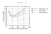
- Shown in FIG. 1 is an example of a graph showing a relation between a loss characteristic of the redox flow battery and a loss rate of the same.
- the loss rate of the battery and that of the converter are minimized when the output of the system is little under 150%, from which it can be seen that the battery loss and the converter loss can be minimized at that time.
- the loss rate of the battery and that of the converter are minimized when the output of the system is about -100%, from which it can be seen that the battery loss and the converter loss can be minimized at that time.
- the battery output and the internal parameter that can allow maximization of the system efficiency (minimization of the loss rate) or can allow minimization of the system loss can be determined.
- the battery output at a regular time interval ( ⁇ t) be represented as x 1 , x 2 , ⁇ , x n , the internal parameter as y, the loss as f(x 1 ,y),f(x 2 ,y),...,f(x n ,y), and the system efficiency at the time of charge or discharge of electricity as ⁇ .
- the battery output x 1 ,x 2 ,..., x n has a probability distribution, so the average x ave gives Eq. 3.1 and the variance ⁇ 2 gives Eq. 3.2.
- third or more order derivatives can be taken as substantially zero.
- a redox flow battery system including generating equipment that varies irregularly in output of power generation, a redox flow battery for smoothing the irregular output of power generation, and a DC/AC converter for converting the battery output was produced, and the loss characteristic of the battery and that of the converter were examined.
- a redox flow battery having the construction shown in FIG. 8 was produced as the redox flow battery and set at a specified battery output of 170kW (about 60% of the specified output of power generation).
- a DC/AC converter having a specified converter output of 275kW was used.
- a histogram of 8-hour battery output for the battery system comprising the generating equipment, the redox flow battery and the converter is shown in FIG. 2. The distribution characteristic is shown below. The standard deviation was determined by smoothing the output of power generation of the generating equipment by using the battery, followed by the output distribution of the battery with respect to the resulting smoothed output of power generation.
- the term of "specified output of battery” means an output at which the system efficiency is maximized during the load smoothing operation of the battery.
- the term of “specified output of converter” means an output at which the conversion efficiency of DC ⁇ AC or AC ⁇ DC
- the internal parameter that can keep the loss characteristic of the converter of the specified output of 275kW is discussed further concretely.
- the case where n converters of the specified output of 275kW are arranged in parallel is considered as the internal parameter.
- the output for each converter is 1/n.
- a variable range of n is 0 ⁇ n ⁇ . Then, 0 can be cited as a possible minimum value n, and infinity can be cited as a possible maximum value, but when n ⁇ 0, g ⁇ , and when n ⁇ , g ⁇ , so n ⁇ 0.28 cited above is an optimum value.
- FIG. 4 shows the expected value of the loss characteristic of the converter (converter loss).
- the loss characteristic of the redox flow battery was determined. The results are shown in FIG. 5. Since the loss characteristic of the battery varies depending on a flow rate of electrolyte per unit time for each cell, the loss characteristic of the battery (battery loss) is determined, varying the flow rate as follows.
- the internal parameter that can keep the loss characteristic of the battery of the specified output of 170kW is discussed further concretely.
- the case where n batteries of the specified output of 170kW are arranged in parallel is considered as the internal parameter.
- the flow rate of electrolyte per unit time for each cell is also determined for the operating condition. Then, the output for each battery is 1/n.
- Coefficients a, b, c of f(x,n) are derived from an approximate expression shown in FIG. 5. Also, the relation between the coefficients a, b, c and the flow rate of electrolyte per unit time for each cell is shown in FIG. 6.
- the graph of FIG. 6 showing the coefficients is plotted, using the coefficients of their respective quadratic functions shown in FIG. 5.
- the specified battery output is in the range of about 40kW to about 100kW (about 0.74 to about 2 times of the standard deviation of 54.1kW), or particularly in the range of about 50kW to about 80kW (about 0.92 to about 1.5 times of the same), the battery loss is reduced and thus the system loss can be reduced. From the foregoing, it can be seen that when the flow rate is set at 0.8 liter/min. ⁇ cell and the specified battery output is set at 66.3kW, the system loss can be minimized.
- the design of the internal parameters such as the specified output of the battery, the specified output of the DC/AC converter, and the flow rate of the electrolyte, can be determined from the basic statistic, using the average value and the variance of the parameters of the battery output and so on which a designer cannot choose voluntarily. It was also confirmed that when at least either of the specified output of battery and the specified output of converter is determined taking the standard deviation into consideration, the system loss can be reduced.
- the specified output of battery is set to be in the range from not less than 0.7 time to not more than 2 times of standard deviation and the specified output of converter is set to be in the range from not less than 1 time to not more than 4 times of the standard deviation. This is because when the specified output of battery and the specified output of converter are in these ranges, respectively, the system loss is reduced further, leading to further improved system efficiency.
- the specified output of the redox flow battery and the specified output of the DC/AC converter were determined from the standard deviation of the battery output determined in the example mentioned above.
- the specified output of the battery was increased by 1.6 times of the standard deviation of 54.1kW and the specified output of the converter was increased by 2.7 times of the standard deviation of the same.
- the specified output of the battery was increased by 1.1 times of the standard deviation of 54.1kW and the specified output of the converter was increased by 3.7 times of the standard deviation of the same.
- the specified output of the battery and that of the converter were determined without any particular consideration of the standard deviation of the battery output. It was found from the test results that the samples No. 2 and No. 3 reduced the battery system loss to approximately half of the sample No. 1.
- the method of designing a redox flow battery system of the present invention can provide the advantageous result that the characteristic function to evaluate the system can be optimized by determining an optimum value of the internal parameter based on the average value of the external parameter and the standard deviation.
- the system loss can be reduced.
- This enables the battery system loss to be reduced without annexing the lead storage battery to the system, as the related art does.
- This can provide a reduced scale of the hardware of the system and thus a more economic system, as compared with the related art. Further, since no lead storage battery is required, production costs can be reduced.
Landscapes
- Life Sciences & Earth Sciences (AREA)
- Engineering & Computer Science (AREA)
- Manufacturing & Machinery (AREA)
- Sustainable Development (AREA)
- Sustainable Energy (AREA)
- Chemical & Material Sciences (AREA)
- Chemical Kinetics & Catalysis (AREA)
- Electrochemistry (AREA)
- General Chemical & Material Sciences (AREA)
- Fuel Cell (AREA)
Applications Claiming Priority (3)
| Application Number | Priority Date | Filing Date | Title |
|---|---|---|---|
| JP2002120157 | 2002-04-23 | ||
| JP2002120157 | 2002-04-23 | ||
| PCT/JP2003/005059 WO2003092110A1 (fr) | 2002-04-23 | 2003-04-21 | Procede de conception d'un systeme de batterie redox a circulation constante |
Publications (4)
| Publication Number | Publication Date |
|---|---|
| EP1536507A1 true EP1536507A1 (fr) | 2005-06-01 |
| EP1536507A4 EP1536507A4 (fr) | 2010-02-03 |
| EP1536507B1 EP1536507B1 (fr) | 2012-06-13 |
| EP1536507B8 EP1536507B8 (fr) | 2012-06-27 |
Family
ID=29267357
Family Applications (1)
| Application Number | Title | Priority Date | Filing Date |
|---|---|---|---|
| EP03717669A Expired - Lifetime EP1536507B8 (fr) | 2002-04-23 | 2003-04-21 | Procede de conception d'un systeme de batterie redox a circulation constante |
Country Status (8)
| Country | Link |
|---|---|
| US (1) | US7704634B2 (fr) |
| EP (1) | EP1536507B8 (fr) |
| JP (1) | JPWO2003092110A1 (fr) |
| AU (1) | AU2003227442B2 (fr) |
| CA (1) | CA2478575C (fr) |
| DK (1) | DK1536507T3 (fr) |
| ES (1) | ES2386780T3 (fr) |
| WO (1) | WO2003092110A1 (fr) |
Families Citing this family (47)
| Publication number | Priority date | Publication date | Assignee | Title |
|---|---|---|---|---|
| JP3970083B2 (ja) * | 2002-04-23 | 2007-09-05 | 住友電気工業株式会社 | レドックスフロー電池システムの運転方法 |
| US7353083B2 (en) * | 2004-01-15 | 2008-04-01 | Vrb Power Systems Inc. | Vanadium redox battery energy storage and power generation system incorporating and optimizing diesel engine generators |
| US8277964B2 (en) | 2004-01-15 | 2012-10-02 | Jd Holding Inc. | System and method for optimizing efficiency and power output from a vanadium redox battery energy storage system |
| US20090239131A1 (en) | 2007-01-16 | 2009-09-24 | Richard Otto Winter | Electrochemical energy cell system |
| US8114541B2 (en) | 2007-01-16 | 2012-02-14 | Primus Power Corporation | Electrochemical energy generation system |
| US7855005B2 (en) * | 2007-02-12 | 2010-12-21 | Deeya Energy, Inc. | Apparatus and methods of determination of state of charge in a redox flow battery |
| JP4986932B2 (ja) * | 2007-05-28 | 2012-07-25 | 本田技研工業株式会社 | 電力供給システム |
| US8587150B2 (en) * | 2008-02-28 | 2013-11-19 | Deeya Energy, Inc. | Method and modular system for charging a battery |
| US7927731B2 (en) * | 2008-07-01 | 2011-04-19 | Deeya Energy, Inc. | Redox flow cell |
| US7820321B2 (en) * | 2008-07-07 | 2010-10-26 | Enervault Corporation | Redox flow battery system for distributed energy storage |
| US8785023B2 (en) * | 2008-07-07 | 2014-07-22 | Enervault Corparation | Cascade redox flow battery systems |
| US20100092843A1 (en) * | 2008-10-10 | 2010-04-15 | Deeya Energy Technologies, Inc. | Venturi pumping system in a hydrogen gas circulation of a flow battery |
| US8230736B2 (en) * | 2008-10-10 | 2012-07-31 | Deeya Energy, Inc. | Level sensor for conductive liquids |
| WO2010042900A1 (fr) * | 2008-10-10 | 2010-04-15 | Deeya Energy Technologies, Inc. | Procédés pour fixer des membranes flexibles poreuses en utilisant un solvant |
| US8236463B2 (en) * | 2008-10-10 | 2012-08-07 | Deeya Energy, Inc. | Magnetic current collector |
| US8231993B2 (en) * | 2008-10-10 | 2012-07-31 | Deeya Energy, Inc. | Flexible multi-walled tubing assembly |
| EP2351184A4 (fr) * | 2008-10-10 | 2014-07-09 | Deeya Energy Technologies Inc | Procédé et appareil permettant d établir l état de charge d une batterie |
| CN102246338B (zh) * | 2008-10-10 | 2014-06-11 | 迪亚能源股份有限公司 | 液流电池元电池的热控制 |
| CN102460812B (zh) * | 2009-05-28 | 2014-12-31 | 艾默吉电力系统股份有限公司 | 由原料制备流通电池电解质 |
| US8587255B2 (en) * | 2009-05-28 | 2013-11-19 | Deeya Energy, Inc. | Control system for a flow cell battery |
| CN102460811B (zh) * | 2009-05-28 | 2015-11-25 | 艾默吉电力系统股份有限公司 | 氧化还原流通单元电池再平衡 |
| US8349477B2 (en) * | 2009-05-28 | 2013-01-08 | Deeya Energy, Inc. | Optical leak detection sensor |
| EP2436080A2 (fr) * | 2009-05-28 | 2012-04-04 | Deeya Energy, Inc. | Compositions d'électrolyte |
| US8723489B2 (en) * | 2009-05-28 | 2014-05-13 | Deeya Energy, Inc. | Bi-directional buck-boost circuit |
| US8551299B2 (en) * | 2009-05-29 | 2013-10-08 | Deeya Energy, Inc. | Methods of producing hydrochloric acid from hydrogen gas and chlorine gas |
| WO2011011533A2 (fr) * | 2009-07-24 | 2011-01-27 | Primus Power Corporation | Système électrochimique comprenant un dispositif de séparation de réactifs |
| US8273472B2 (en) * | 2010-02-12 | 2012-09-25 | Primus Power Corporation | Shunt current interruption in electrochemical energy generation system |
| US8951665B2 (en) * | 2010-03-10 | 2015-02-10 | Imergy Power Systems, Inc. | Methods for the preparation of electrolytes for chromium-iron redox flow batteries |
| US10651492B2 (en) | 2010-06-22 | 2020-05-12 | Vrb Energy Inc. | Integrated system for electrochemical energy storage system |
| US9281535B2 (en) | 2010-08-12 | 2016-03-08 | Imergy Power Systems, Inc. | System dongle |
| US8202641B2 (en) * | 2010-09-08 | 2012-06-19 | Primus Power Corporation | Metal electrode assembly for flow batteries |
| US8450001B2 (en) | 2010-09-08 | 2013-05-28 | Primus Power Corporation | Flow batter with radial electrolyte distribution |
| US8709629B2 (en) | 2010-12-22 | 2014-04-29 | Jd Holding Inc. | Systems and methods for redox flow battery scalable modular reactant storage |
| CN103339762B (zh) | 2011-01-13 | 2016-03-30 | 伊莫基动力系统公司 | 液流电池单元堆 |
| US8980484B2 (en) | 2011-03-29 | 2015-03-17 | Enervault Corporation | Monitoring electrolyte concentrations in redox flow battery systems |
| US8916281B2 (en) | 2011-03-29 | 2014-12-23 | Enervault Corporation | Rebalancing electrolytes in redox flow battery systems |
| US9478803B2 (en) | 2011-06-27 | 2016-10-25 | Primus Power Corporation | Electrolyte flow configuration for a metal-halogen flow battery |
| US8137831B1 (en) | 2011-06-27 | 2012-03-20 | Primus Power Corporation | Electrolyte flow configuration for a metal-halogen flow battery |
| US10141594B2 (en) | 2011-10-07 | 2018-11-27 | Vrb Energy Inc. | Systems and methods for assembling redox flow battery reactor cells |
| US9853454B2 (en) | 2011-12-20 | 2017-12-26 | Jd Holding Inc. | Vanadium redox battery energy storage system |
| US9020799B2 (en) * | 2012-02-14 | 2015-04-28 | GM Global Technology Operations LLC | Analytic method of fuel consumption optimized hybrid concept for fuel cell systems |
| US9130217B2 (en) | 2012-04-06 | 2015-09-08 | Primus Power Corporation | Fluidic architecture for metal-halogen flow battery |
| US8928327B2 (en) | 2012-11-20 | 2015-01-06 | Primus Power Corporation | Mass distribution indication of flow battery state of charge |
| US9490496B2 (en) | 2013-03-08 | 2016-11-08 | Primus Power Corporation | Reservoir for multiphase electrolyte flow control |
| US20160233679A1 (en) * | 2013-10-18 | 2016-08-11 | State Grid Corporation Of China | A method and system for control of smoothing the energy storage in wind phtovolatic power fluctuation based on changing rate |
| US10290891B2 (en) | 2016-01-29 | 2019-05-14 | Primus Power Corporation | Metal-halogen flow battery bipolar electrode assembly, system, and method |
| CN114039076A (zh) | 2021-11-02 | 2022-02-11 | 北京普能世纪科技有限公司 | 一种全钒液流电池分散式规模化系统 |
Family Cites Families (11)
| Publication number | Priority date | Publication date | Assignee | Title |
|---|---|---|---|---|
| JPS61218070A (ja) | 1985-03-22 | 1986-09-27 | Sanyo Electric Co Ltd | 非水電解液電池 |
| US4786567A (en) | 1986-02-11 | 1988-11-22 | Unisearch Limited | All-vanadium redox battery |
| JPH0412464A (ja) * | 1990-05-01 | 1992-01-17 | Sumitomo Electric Ind Ltd | レドックスフロー電池およびその運転方法 |
| US5083039B1 (en) * | 1991-02-01 | 1999-11-16 | Zond Energy Systems Inc | Variable speed wind turbine |
| US6111767A (en) * | 1998-06-22 | 2000-08-29 | Heliotronics, Inc. | Inverter integrated instrumentation having a current-voltage curve tracer |
| JP2000073931A (ja) * | 1998-08-28 | 2000-03-07 | Hitachi Engineering & Services Co Ltd | 風力発電設備 |
| JP2000078895A (ja) * | 1998-08-28 | 2000-03-14 | Hitachi Engineering & Services Co Ltd | 風力発電設備 |
| JP2000073932A (ja) | 1998-08-28 | 2000-03-07 | Hitachi Engineering & Services Co Ltd | 風力発電設備 |
| JP3352662B2 (ja) * | 2000-02-03 | 2002-12-03 | 関西電力株式会社 | 二次電池システムを用いた電力系統安定化装置および電力系統安定化方法 |
| JP2001339995A (ja) * | 2000-05-25 | 2001-12-07 | Ishikawajima Harima Heavy Ind Co Ltd | 風力発電出力安定化装置及び方法 |
| WO2003017407A1 (fr) * | 2001-08-10 | 2003-02-27 | Eda, Inc. | Batterie a egalisation de charge amelioree et procedes correspondants |
-
2003
- 2003-04-21 ES ES03717669T patent/ES2386780T3/es not_active Expired - Lifetime
- 2003-04-21 US US10/511,546 patent/US7704634B2/en not_active Expired - Fee Related
- 2003-04-21 CA CA2478575A patent/CA2478575C/fr not_active Expired - Fee Related
- 2003-04-21 DK DK03717669.0T patent/DK1536507T3/da active
- 2003-04-21 WO PCT/JP2003/005059 patent/WO2003092110A1/fr not_active Ceased
- 2003-04-21 AU AU2003227442A patent/AU2003227442B2/en not_active Ceased
- 2003-04-21 JP JP2004500360A patent/JPWO2003092110A1/ja active Pending
- 2003-04-21 EP EP03717669A patent/EP1536507B8/fr not_active Expired - Lifetime
Also Published As
| Publication number | Publication date |
|---|---|
| AU2003227442B2 (en) | 2008-06-19 |
| EP1536507A4 (fr) | 2010-02-03 |
| AU2003227442A1 (en) | 2003-11-10 |
| US20050181273A1 (en) | 2005-08-18 |
| ES2386780T3 (es) | 2012-08-30 |
| CA2478575C (fr) | 2011-01-04 |
| EP1536507B8 (fr) | 2012-06-27 |
| JPWO2003092110A1 (ja) | 2005-09-02 |
| US7704634B2 (en) | 2010-04-27 |
| EP1536507B1 (fr) | 2012-06-13 |
| CA2478575A1 (fr) | 2003-11-06 |
| WO2003092110A1 (fr) | 2003-11-06 |
| DK1536507T3 (da) | 2012-07-23 |
Similar Documents
| Publication | Publication Date | Title |
|---|---|---|
| EP1536507A1 (fr) | Procede de conception d'un systeme de batterie redox a circulation constante | |
| US7061205B2 (en) | Method for operating redox flow battery system | |
| Chen et al. | Multiple model predictive control for a hybrid proton exchange membrane fuel cell system | |
| Alvarez et al. | Microgrids multiobjective design optimization for critical loads | |
| JP4984207B2 (ja) | レドックスフロー電池システム | |
| US20130241495A1 (en) | Energy storage system and method of controlling the same | |
| CN113682161B (zh) | 一种混动汽车的燃料电池控制方法、装置、设备及介质 | |
| CN111983494B (zh) | 一种提高电池系统使用寿命的方法及系统 | |
| CN109494771B (zh) | 基于超级电容器荷电状态预测的新能源功率平滑控制方法 | |
| CN110231566A (zh) | 一种电能管控系统 | |
| JP2018113158A (ja) | 車両用燃料電池システム及びその制御方法 | |
| WO2016132580A1 (fr) | Dispositif de régulation de charge et de décharge, corps mobile, et procédé de détermination de quantité d'attribution de puissance électrique | |
| Vašak et al. | A battery management system for efficient adherence to energy exchange commands under longevity constraints | |
| EP4283813A1 (fr) | Système d'électrolyse de l'eau gérant l'alimentation en énergie renouvelable | |
| Choi et al. | Application of vanadium redox flow battery to grid connected microgrid energy management | |
| EP3261211B1 (fr) | Systèmes et procédés de réglage de paramètres de performance d'un dispositif de stockage d'énergie | |
| CN117277596A (zh) | 一种基于储能设备的供电控制系统及方法 | |
| CN117133950A (zh) | 一种针对燃料电池系统的控制参数调控方法及系统 | |
| CN117081180A (zh) | 电压无功控制方法、装置、存储介质及计算机设备 | |
| CN114435155B (zh) | 基于凸函数的燃料电池和电池混合动力系统能量控制方法 | |
| KR102064586B1 (ko) | 에너지 저장 시스템의 충전 관리 방법 | |
| Araujo et al. | Smartbattery: An active-battery solution for energy storage system | |
| CN117728498B (zh) | 一种应用储能装置的电网稳定性的控制方法 | |
| KR102053812B1 (ko) | 하이브리드 배터리에 연결된 전력 변환 시스템을 제어하기 위한 방법 및 시스템 | |
| Gonschorowski et al. | Adaptive Frequency-Based Power Management for Off-Grid Hybrid Photovoltaic Converters |
Legal Events
| Date | Code | Title | Description |
|---|---|---|---|
| PUAI | Public reference made under article 153(3) epc to a published international application that has entered the european phase |
Free format text: ORIGINAL CODE: 0009012 |
|
| 17P | Request for examination filed |
Effective date: 20041119 |
|
| AK | Designated contracting states |
Kind code of ref document: A1 Designated state(s): AT BE BG CH CY CZ DE DK EE ES FI FR GB GR HU IE IT LI LU MC NL PT RO SE SI SK TR |
|
| AX | Request for extension of the european patent |
Extension state: AL LT LV MK |
|
| A4 | Supplementary search report drawn up and despatched |
Effective date: 20100107 |
|
| 17Q | First examination report despatched |
Effective date: 20100528 |
|
| GRAP | Despatch of communication of intention to grant a patent |
Free format text: ORIGINAL CODE: EPIDOSNIGR1 |
|
| GRAS | Grant fee paid |
Free format text: ORIGINAL CODE: EPIDOSNIGR3 |
|
| RIN1 | Information on inventor provided before grant (corrected) |
Inventor name: TOKUDA, NOBUYUKI,THE KANSAI ELECT. POWER CO. INC. Inventor name: DEGUCHI, HIROSHIGE,SUMITOMO ELECT. INDUST. LTD Inventor name: SHIGEMATSU, TOSHIO,SUMITOMO ELECT. INDUST. LTD |
|
| GRAA | (expected) grant |
Free format text: ORIGINAL CODE: 0009210 |
|
| RAP1 | Party data changed (applicant data changed or rights of an application transferred) |
Owner name: SUMITOMO ELECTRIC INDUSTRIES, LTD. Owner name: THE KANSAI ELECTRIC POWER CO., INC. |
|
| AK | Designated contracting states |
Kind code of ref document: B1 Designated state(s): DE DK ES FR GB IT |
|
| REG | Reference to a national code |
Ref country code: GB Ref legal event code: FG4D |
|
| RAP2 | Party data changed (patent owner data changed or rights of a patent transferred) |
Owner name: SUMITOMO ELECTRIC INDUSTRIES, LTD. Owner name: THE KANSAI ELECTRIC POWER CO., INC. |
|
| REG | Reference to a national code |
Ref country code: DK Ref legal event code: T3 |
|
| REG | Reference to a national code |
Ref country code: DE Ref legal event code: R096 Ref document number: 60341252 Country of ref document: DE Effective date: 20120809 |
|
| REG | Reference to a national code |
Ref country code: ES Ref legal event code: FG2A Ref document number: 2386780 Country of ref document: ES Kind code of ref document: T3 Effective date: 20120830 |
|
| PLBE | No opposition filed within time limit |
Free format text: ORIGINAL CODE: 0009261 |
|
| STAA | Information on the status of an ep patent application or granted ep patent |
Free format text: STATUS: NO OPPOSITION FILED WITHIN TIME LIMIT |
|
| 26N | No opposition filed |
Effective date: 20130314 |
|
| REG | Reference to a national code |
Ref country code: DE Ref legal event code: R097 Ref document number: 60341252 Country of ref document: DE Effective date: 20130314 |
|
| REG | Reference to a national code |
Ref country code: FR Ref legal event code: PLFP Year of fee payment: 14 |
|
| REG | Reference to a national code |
Ref country code: FR Ref legal event code: PLFP Year of fee payment: 15 |
|
| REG | Reference to a national code |
Ref country code: FR Ref legal event code: PLFP Year of fee payment: 16 |
|
| PGFP | Annual fee paid to national office [announced via postgrant information from national office to epo] |
Ref country code: FR Payment date: 20190313 Year of fee payment: 17 |
|
| PGFP | Annual fee paid to national office [announced via postgrant information from national office to epo] |
Ref country code: IT Payment date: 20190419 Year of fee payment: 17 Ref country code: ES Payment date: 20190506 Year of fee payment: 17 Ref country code: DK Payment date: 20190410 Year of fee payment: 17 Ref country code: DE Payment date: 20190410 Year of fee payment: 17 |
|
| PGFP | Annual fee paid to national office [announced via postgrant information from national office to epo] |
Ref country code: GB Payment date: 20190417 Year of fee payment: 17 |
|
| REG | Reference to a national code |
Ref country code: DE Ref legal event code: R119 Ref document number: 60341252 Country of ref document: DE |
|
| REG | Reference to a national code |
Ref country code: DK Ref legal event code: EBP Effective date: 20200430 |
|
| PG25 | Lapsed in a contracting state [announced via postgrant information from national office to epo] |
Ref country code: FR Free format text: LAPSE BECAUSE OF NON-PAYMENT OF DUE FEES Effective date: 20200430 Ref country code: DE Free format text: LAPSE BECAUSE OF NON-PAYMENT OF DUE FEES Effective date: 20201103 |
|
| GBPC | Gb: european patent ceased through non-payment of renewal fee |
Effective date: 20200421 |
|
| PG25 | Lapsed in a contracting state [announced via postgrant information from national office to epo] |
Ref country code: DK Free format text: LAPSE BECAUSE OF NON-PAYMENT OF DUE FEES Effective date: 20200430 Ref country code: GB Free format text: LAPSE BECAUSE OF NON-PAYMENT OF DUE FEES Effective date: 20200421 |
|
| REG | Reference to a national code |
Ref country code: ES Ref legal event code: FD2A Effective date: 20210903 |
|
| PG25 | Lapsed in a contracting state [announced via postgrant information from national office to epo] |
Ref country code: IT Free format text: LAPSE BECAUSE OF NON-PAYMENT OF DUE FEES Effective date: 20200421 |
|
| PG25 | Lapsed in a contracting state [announced via postgrant information from national office to epo] |
Ref country code: ES Free format text: LAPSE BECAUSE OF NON-PAYMENT OF DUE FEES Effective date: 20200422 |