EP1536594A1 - Système redondant de transmission d'information basé sur deux lignes de transmission parallèles et procédé correspondant - Google Patents
Système redondant de transmission d'information basé sur deux lignes de transmission parallèles et procédé correspondant Download PDFInfo
- Publication number
- EP1536594A1 EP1536594A1 EP04255004A EP04255004A EP1536594A1 EP 1536594 A1 EP1536594 A1 EP 1536594A1 EP 04255004 A EP04255004 A EP 04255004A EP 04255004 A EP04255004 A EP 04255004A EP 1536594 A1 EP1536594 A1 EP 1536594A1
- Authority
- EP
- European Patent Office
- Prior art keywords
- transmission
- information
- terminals
- data
- terminal
- Prior art date
- Legal status (The legal status is an assumption and is not a legal conclusion. Google has not performed a legal analysis and makes no representation as to the accuracy of the status listed.)
- Granted
Links
- 230000005540 biological transmission Effects 0.000 title claims abstract description 350
- 238000000034 method Methods 0.000 title claims description 17
- 238000005096 rolling process Methods 0.000 claims description 20
- 230000015556 catabolic process Effects 0.000 description 6
- 238000004891 communication Methods 0.000 description 5
- 238000010586 diagram Methods 0.000 description 4
- 238000005516 engineering process Methods 0.000 description 3
- 230000006870 function Effects 0.000 description 2
- 230000009365 direct transmission Effects 0.000 description 1
- 238000012986 modification Methods 0.000 description 1
- 230000004048 modification Effects 0.000 description 1
- 230000004044 response Effects 0.000 description 1
Images





Classifications
-
- H—ELECTRICITY
- H04—ELECTRIC COMMUNICATION TECHNIQUE
- H04L—TRANSMISSION OF DIGITAL INFORMATION, e.g. TELEGRAPHIC COMMUNICATION
- H04L12/00—Data switching networks
- H04L12/28—Data switching networks characterised by path configuration, e.g. LAN [Local Area Networks] or WAN [Wide Area Networks]
- H04L12/40—Bus networks
- H04L12/40169—Flexible bus arrangements
- H04L12/40176—Flexible bus arrangements involving redundancy
- H04L12/40182—Flexible bus arrangements involving redundancy by using a plurality of communication lines
-
- H—ELECTRICITY
- H04—ELECTRIC COMMUNICATION TECHNIQUE
- H04L—TRANSMISSION OF DIGITAL INFORMATION, e.g. TELEGRAPHIC COMMUNICATION
- H04L12/00—Data switching networks
- H04L12/28—Data switching networks characterised by path configuration, e.g. LAN [Local Area Networks] or WAN [Wide Area Networks]
- H04L12/40—Bus networks
- H04L12/407—Bus networks with decentralised control
-
- H—ELECTRICITY
- H04—ELECTRIC COMMUNICATION TECHNIQUE
- H04L—TRANSMISSION OF DIGITAL INFORMATION, e.g. TELEGRAPHIC COMMUNICATION
- H04L12/00—Data switching networks
- H04L12/28—Data switching networks characterised by path configuration, e.g. LAN [Local Area Networks] or WAN [Wide Area Networks]
- H04L12/40—Bus networks
- H04L2012/40267—Bus for use in transportation systems
- H04L2012/40293—Bus for use in transportation systems the transportation system being a train
Definitions
- the present invention relates to an improved information transmission system which can continue transmitting even at the time of failure and an improved information transmission method.
- the network technology for a rolling stock which can continue transmitting even if multiple troubles occur is disclosed in Japanese Patent Application Laid-Open No. 11-154891.
- two transmission stations are provided respectively in each car.
- the transmission stations in each car is assumed to be a first transmission line, the loop connection is done, and two terminals in each car are connected to each other as the second transmission line.
- the transmission can be continued by forming the detour with the second transmission line when the trouble occurs in the first transmission line.
- the initialization processing is carried out by transmitting data for configuration management in order to confirm the configuration of the equipment. Afterwards, the transmission of usual control data begins. The state of transmission and network configuration are always checked at this time by the control data to be controlled and configuration management data.
- the technology described in Japanese Patent Application Laid-Open No. 11-154891 prevents transmission being cut off by the change in the transmission route for the trouble of the transmission line caused while transmitting data.
- the exchange of route information by the configuration management data is indispensable to recognize between the transmission terminals the route possible to communicate to achieve this. Therefore, it is necessary to initialize again to select the transmission route after the occurrence of failure.
- the exchange of route information is not easy, and the processing is complex and takes time because there is a trouble in the transm ission line.
- An object of the present invention is to provide an information transmission system that can continue transmitting without exchanging route information even at the time of multiple troubles, and that has the simple and reliable configuration.
- an information transmission system has two transmission lines, and two or more transmission terminals connected with these transmission lines, which can transmit information mutually, wherein each transmission terminal receives the same information through two transmission lines, and has a means by which the information received from other transmission termi nals is transferred when information is sent to other transmission terminals.
- the present invention When the present invention is applied to the transmission of the configuration management data, the initialization can be carried out even at troubles.
- Transmission terminals 111, 121, 112, 122, 113, 123, 114, and 124 are provided in each car of car 1 11 to car 4 14.
- the transmission terminals of each car configure a duplex system to secure redundancy.
- the terminals 111 to 114 shown upward configure a 1 st system, and the terminals 121 to 124 shown downward config ure a second system.
- These transmission terminals 111 to 114 and 121 to 124 are connected to both of 1st main transmission line 21 and 2nd main transmission line 22 to ensure the data transmission between the transmission terminals.
- Line concentrators 211 to 214 and 221 to 224 (It is called hubs) are used for the connection of each transmission terminal and both main transmission lines 21, 22.
- Plural equipment in the car is connected to each transmission terminal 111 to 114 and 121 to 124 though omitted in FIG. 1.
- FIG. 2 shows the connection configuration of equipment in the car in the information transmission system for a rolling stock according to the first embodiment of the present invention.
- car 2 12 is shown as one example.
- Each equipment is connected with transmission terminals 112, 122 by using two branch transmission lines 31 and 32.
- Branch line transmission line 31 connects equipment such as inverters 41 and brakes 42 arranged under the floor.
- Branch line transmission line 32 connects equipment such as indicator 43, broadcaster 44, door 45, and air conditioner 46 arranged above the floor.
- transmission terminal 112 and 122 are arranged at both ends of branch line transmission lines 31 and 32 and each equipment is connected in the middle thereof so that it may become possible to communicate with either transmission terminal 112 or 122 even when the breakdown such as the disconnection etc. occurs in the part of main transmission lines 21 and 22.
- the equipment in the car can mutually transmit the instruction value and status information, etc. via branch line transmission lines 31, 32, line concentrators 212, 222, and main transmission lines 21, 22.
- the transmission terminal of data source station transmits the same data to both main transmission lines 21 and 22. If any troubles do not occur in the network, other transmission terminals receive the same data from each transmission terminals through both main transmission lines 21 and 22.
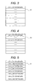
- FIG. 3 to FIG. 5 show the structure of the transmission data in the information transmission system for a rolling stock according to the first embodiment of the present invention.
- the columns which describes the data of not only the source transmission terminal but also all the transmission terminals are provided in the transmission data.
- FIG. 3 is a structure view of data D1 transmitted from 1st system transmission terminal 111 of car 1 at the first time after starting as shown by sign (1) of FIG. 1.
- transmission data D1 transmitted from 1st system transmission terminal 111 of car 1 at the first time after starting as shown by sign (1) of FIG. 1.
- FIG. 4 is a structure view of data D2 transmitted from 1st system transmission terminal 112 of car 2 as shown by sign (2) of FIG. 1.
- Data "Car 2 and 1 st system data" of car 2 of the source transmission terminal 112 is transmitted along with the content of data D1 of the 1 st system transmission terminal of car 1 received when the above-mentioned data D1 from 1st system transmission terminal 111 of car 1 is received.
- This data D2 reaches all the transmission terminals through either of 1 st system or 2nd system main transmission line as shown in FIG. 1.
- transmission terminal 112 of the 1st system of car 2 relays data D1 of transmission terminal 111 of the 1 st system of car 1 which was not able to be transmitted directly due to the trouble of transmission line.
- Other transmission terminals also transmit the data of the source terminal and the data from other transmission terminals received in a similar way. And, each terminal repeats the transmission at a suitable cycle (for instance, 10ms). As a result, all terminals can receive the data from all other terminals.
- FIG. 5 shows transmission data DI in the state to receive the data from all of other terminals.
- transmission terminal 111 of the 1st system of car 1 transmits first, and transmission terminal 112 of the 1st system of car 2 transmits next.
- Each transmission terminal can transmit data at an arbitrary timing. Because each terminal periodically repeats the transmission, an information interchange each other becomes possible.
- both of the data from the source terminal and the data received from other terminals is not necessarily transmitted every time. For instance, the data from the source terminal is transmitted every time, but the data received from other terminals is transmitted once every two or more times, or both are alternately transmitted.
- Various modifications are considered.
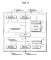
- FIG. 6 is a block diagram showing the outline configuration of a transmission terminal in the information transmission system for a rolling stock according to the first embodiment of the present invention.
- Transmission terminal 112 comprises communication control part 51 which does the transmission with main transmission lines 21, 22, and equipment control unit 52 which does the communication with the each equipment in the car.
- Communication control parts 51 comprises send and receive part 61, 62 connected with main transmission lines 21, 22, respectively, microcomputer 65 which controls these send and receive parts, and memory 67.
- Memory 67 is used as a temporary storage in the send and receive part to maintain table 72 in which the transmission data shown in FIG. 3 to FIG. 5 is written.
- Send and receive part 61, 62, and microcomputer 65 are connected with bus 69.
- Equipment control unit 52 comprises send and receive part 63, 64 connected to branch transmission lines 31, 32, and microcomputer 66 which does data processing.
- Memory 68 is used as a temporary memory at data processing.
- Send and receive part 63, 64, and microcomputer 66 are connected with bus 70.
- Branch transmission lines 31, 32 are connected to under-floor equipment 41, 42, and up-floor equipment 43 to 46, respectively, as explained by FIG. 2.
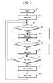
- FIG. 7 is a processing flowchart of the data receiving at the transmission terminal in the first embodiment of the present invention.
- the processing starts from step 701.
- step 702 the timer by which the transmission interval is decided is started. This timer counts one cycle, for instance, 10 ms and times out.
- the receiving processing in steps 703 to 706 is repeated until this time-out is detected in step 707 described later.
- a data table is overwritten in step 704.
- the data received from one transmission terminal as shown in FIG. 5 includes the data of all the transmission terminals. Therefore, the data of the same transmission terminal will be received from different transmission terminals two or more times. At this time, older data than the data which has already been recorded in the table is occasionally received according to timing. Data is sequentially numbered for instance in the source station to always update the data of the table to be the latest one, and only when the number of received data is larger than the number of the data of the table, the received data is described in the table in destination station.
- step 705 When data is received from 2nd systems main transmission line 22 in step 705, data table is overwritten in step 706.
- the processing at this time is the same as receiving processing steps 703, 704 from 1 st system main transmission line 21.
- the data described in the table does not have the necessity for distinguishing the data from which 1 st system or 2nd systems. Only the latest data is always overwritten.
- step 707 the transmission processing of the table is done in step 708.
- the data of the source transmission terminal is described in the table based on the data received from branch line transmission lines 31 and 32.
- the table is transmitted to both main transmission lines 21 and 22. Further, necessary data for the each equipment is transmitted based on the data of the table through branch line transmission lines 31 and 32.
- the timer is reset in step 709, and the processing shifts to the receiving processing at the next cycle.
- FIG. 8 shows the configuration of the information transmission system when the car is divided in the first embodiment of the present invention.
- the equipment configuration of each car is basically the same as FIG. 1. Therefore, the same sign is given to avoid the repetition of the explanation.
- Network configuration is the same even when dividing except that 1 st and 2nd main transmission lines 21 and 22 are divided into 21-1, 21-2, and 22-1, 22-2, respectively. Therefore, data can be transmitted according to a similar procedure even after dividing.
- the network configuration can return the same one as FIG. 1, and can transmit data.
- the data of the transmission terminal and the data received from other transmission terminals are transmitted to both of two main transmission lines in this embodiment. Therefore, other transmission terminals will relay even when the trouble occurs, and direct transmission of the data is impossible and the data transmission becomes possible. Therefore, even if a multiple breakdown happens, the communication can be continued without cutting off. Moreover, the processing at the transmission terminal at the trouble is quite the same as that when it is normal, and the information interchange between the transmission terminals is unnecessary. Moreover, temporary interruption of the transmission due to the trouble is not occurred.
- the efficiency of the network lowers comparatively because not only the data of the source transmission terminal but also the d ata of other transmission terminals are transmitted simultaneously in this embodiment. Therefore, when the amount of the data to be transmitted is a little, this embodiment is especially suitable.
- this embodiment When this embodiment is applied to the transmission of the configuration management data to confirm the address of the equipment and the state, etc. when the network is initialized, the information interchange between the transmission terminals is easily carried out even due to the trouble in the network. In general, the amount of the configuration management data is a little, and it is best for the application of this embodiment.
- this embodiment When this embodiment is applied to the data transmission (the transmission of control information of the equipment etc.) after initial izing, it is possible to construct easily the network which is strong for the trouble. However, it takes several times time of the transmission cycle to transmit data to all the transmission terminals at the trouble. Therefore, it is preferable to set the transmission cycle shorter than the response time necessary to control the equipment.
- FIG. 9 shows the configuration of an information transmission system for a rolling stock according to a second embodiment of the present invention and the transmission procedure of data.
- each transmission terminal was assumed to be one to transmit data to main transmission lines 21 and 22 of 1st and 2nd system.
- Transmission terminal 111 to 114 of 1st system transmit the data to main transmission line 21 of 1 st system in the 2nd embodiment
- transmission terminal 121 to 124 of 2nd system transmit the data to main transmission line 22 of 2nd system.
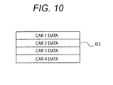
- FIG. 10 shows the transmission data in the information transmission system for a rolling stock according to the second embodiment of the present invention.
- Transmission data D3 in this embodiment is provided only every cars though the data is provided every cars and systems in the first embodiment, and the system is not distinguished.
- the data of the source transmission terminal which the transmission terminal of 1 st system and the transmission terminal of 2nd system t ransmit is assumed to be the same one.
- the number of car is written to the corresponding car column of table regardless of the data received from which system in source station.
- Transmission terminal 112,122 of car 2 relays the data of car 1 which was not able to be transmitted directly due to the trouble of transmission line. It is, therefore, possible to transmit the data to all the transmission terminals.
- Other transmission terminals transmit the data of the source transmission terminal and the data received from other transmission terminals in a similar way.
- each terminal repeats the transmission at a suitable cycle, for instance, 10 ms. As a result; all terminals can receive the data from all other terminals.
- each transmission terminal of 1 st system and 2nd system should be assumed to be similar in each car, and peculiar information on each transmission terminal like the inside information etc. of the transmission terminal cannot be transmitted.
- both systems should always operate in the second embodiment though the transmission between equipment is possible if the transmission terminal of one system works in the first embodiment, in which a standby duplex system is composed.
- FIG. 11 is a block diagram showing the configuration of the information transmission system for a rolling stock according to a third embodime nt of the present invention. The same sign is put on the same part as FIG. 1 here to avoid the repetition of the explanation.
- the point that transmission terminals 111 to 114 of car 11 to 14 are not made duplex is different from the configuration of the fi rst embodiment.
- This configuration is a single system.
- the configuration of the transmission terminals, the point that these transmission terminals have the function of receiving data from both main transmission lines 21 and 22, and the point that each equipment in car is connected to the transmission terminal, etc. are similar to the first embodiment.
- transmission data of the transmission terminal contains the data received from other transmission terminals, and the configuration is assumed to be the same one as the transmission data in the second embodiment of the present invention.
- data can be transmitted even if multiple troubles occur as well as the first embodiment previously explained, the transmission terminal of each car is in single type, and the configuration of the device becomes simpler. However, because this embodiment is not multiplexed, the reliability to the breakdown of the transmission terminal is inferior. Howe ver, because the network is a duplex system, and the relay function of data is provided, this embodiment is also made highly reliable as well as the first embodiment.
Landscapes
- Engineering & Computer Science (AREA)
- Computer Networks & Wireless Communication (AREA)
- Signal Processing (AREA)
- Electric Propulsion And Braking For Vehicles (AREA)
- Small-Scale Networks (AREA)
Applications Claiming Priority (2)
| Application Number | Priority Date | Filing Date | Title |
|---|---|---|---|
| JP2003393520A JP4358608B2 (ja) | 2003-11-25 | 2003-11-25 | 情報伝送システム及び情報伝送方法 |
| JP2003393520 | 2003-11-25 |
Publications (2)
| Publication Number | Publication Date |
|---|---|
| EP1536594A1 true EP1536594A1 (fr) | 2005-06-01 |
| EP1536594B1 EP1536594B1 (fr) | 2007-10-10 |
Family
ID=34463771
Family Applications (1)
| Application Number | Title | Priority Date | Filing Date |
|---|---|---|---|
| EP04255004A Expired - Lifetime EP1536594B1 (fr) | 2003-11-25 | 2004-08-19 | Système redondant de transmission d'information basé sur deux lignes de transmission parallèles et procédé correspondant |
Country Status (4)
| Country | Link |
|---|---|
| EP (1) | EP1536594B1 (fr) |
| JP (1) | JP4358608B2 (fr) |
| CN (1) | CN100525134C (fr) |
| DE (1) | DE602004009389T2 (fr) |
Cited By (4)
| Publication number | Priority date | Publication date | Assignee | Title |
|---|---|---|---|---|
| EP2139171A4 (fr) * | 2007-03-20 | 2011-05-04 | Mitsubishi Electric Corp | Appareil de communication destiné à du matériel roulant |
| EP2792572A4 (fr) * | 2011-12-12 | 2015-08-12 | Mitsubishi Electric Corp | Dispositif et procédé de gestion d'informations sur des trains |
| CN105027455A (zh) * | 2013-03-11 | 2015-11-04 | 三菱电机株式会社 | 列车信息管理装置 |
| US9553931B2 (en) | 2012-01-04 | 2017-01-24 | Mitsubishi Electric Corporation | Train-information managing apparatus |
Families Citing this family (3)
| Publication number | Priority date | Publication date | Assignee | Title |
|---|---|---|---|---|
| JP4881223B2 (ja) * | 2007-05-24 | 2012-02-22 | 株式会社東芝 | 鉄道車両用伝送システム及び伝送切換器 |
| ES2384591T3 (es) | 2007-12-06 | 2012-07-09 | Mitsubishi Electric Corporation | Aparato de comunicación entre vehículos de tren |
| JP7257922B2 (ja) * | 2019-09-06 | 2023-04-14 | 株式会社日立製作所 | 車両情報制御システム |
Citations (4)
| Publication number | Priority date | Publication date | Assignee | Title |
|---|---|---|---|---|
| US5187709A (en) * | 1990-05-08 | 1993-02-16 | Caterpillar Inc. | Fault tolerant serial communications network |
| EP0854610A2 (fr) * | 1997-01-16 | 1998-07-22 | Yamatake-Honeywell Co. Ltd. | Méthode redondante pour des communications Ethernet |
| WO2001063850A1 (fr) * | 2000-02-25 | 2001-08-30 | Honeywell International Inc. | Tolerance aux pannes de reseau multiples grace a une gestion redondante du reseau |
| US20020027877A1 (en) * | 2000-09-02 | 2002-03-07 | Agency For Defense Development | Packet processing method using multiple fault tolerant network structure |
-
2003
- 2003-11-25 JP JP2003393520A patent/JP4358608B2/ja not_active Expired - Fee Related
-
2004
- 2004-07-09 CN CNB2004100634889A patent/CN100525134C/zh not_active Expired - Lifetime
- 2004-08-19 DE DE200460009389 patent/DE602004009389T2/de not_active Expired - Lifetime
- 2004-08-19 EP EP04255004A patent/EP1536594B1/fr not_active Expired - Lifetime
Patent Citations (4)
| Publication number | Priority date | Publication date | Assignee | Title |
|---|---|---|---|---|
| US5187709A (en) * | 1990-05-08 | 1993-02-16 | Caterpillar Inc. | Fault tolerant serial communications network |
| EP0854610A2 (fr) * | 1997-01-16 | 1998-07-22 | Yamatake-Honeywell Co. Ltd. | Méthode redondante pour des communications Ethernet |
| WO2001063850A1 (fr) * | 2000-02-25 | 2001-08-30 | Honeywell International Inc. | Tolerance aux pannes de reseau multiples grace a une gestion redondante du reseau |
| US20020027877A1 (en) * | 2000-09-02 | 2002-03-07 | Agency For Defense Development | Packet processing method using multiple fault tolerant network structure |
Non-Patent Citations (2)
| Title |
|---|
| PATENT ABSTRACTS OF JAPAN vol. 0170, no. 81 (E - 1321) 18 February 1993 (1993-02-18) * |
| ROSTAMZADEH B ET AL: "DACAPO: a distributed computer architecture for safety-critical control applications", INTELLIGENT VEHICLES '95 SYMPOSIUM., PROCEEDINGS OF THE DETROIT, MI, USA 25-26 SEPT. 1995, NEW YORK, NY, USA,IEEE, US, 25 September 1995 (1995-09-25), pages 376 - 381, XP010194147, ISBN: 0-7803-2983-X * |
Cited By (6)
| Publication number | Priority date | Publication date | Assignee | Title |
|---|---|---|---|---|
| EP2139171A4 (fr) * | 2007-03-20 | 2011-05-04 | Mitsubishi Electric Corp | Appareil de communication destiné à du matériel roulant |
| US8488617B2 (en) | 2007-03-20 | 2013-07-16 | Mitsubishi Electric Corporation | Railway-train communication apparatus |
| EP2792572A4 (fr) * | 2011-12-12 | 2015-08-12 | Mitsubishi Electric Corp | Dispositif et procédé de gestion d'informations sur des trains |
| US9553931B2 (en) | 2012-01-04 | 2017-01-24 | Mitsubishi Electric Corporation | Train-information managing apparatus |
| CN105027455A (zh) * | 2013-03-11 | 2015-11-04 | 三菱电机株式会社 | 列车信息管理装置 |
| CN105027455B (zh) * | 2013-03-11 | 2017-05-03 | 三菱电机株式会社 | 列车信息管理装置 |
Also Published As
| Publication number | Publication date |
|---|---|
| EP1536594B1 (fr) | 2007-10-10 |
| DE602004009389D1 (de) | 2007-11-22 |
| JP2005159604A (ja) | 2005-06-16 |
| CN100525134C (zh) | 2009-08-05 |
| DE602004009389T2 (de) | 2008-07-10 |
| CN1622484A (zh) | 2005-06-01 |
| JP4358608B2 (ja) | 2009-11-04 |
Similar Documents
| Publication | Publication Date | Title |
|---|---|---|
| US6282669B1 (en) | Ethernet communication redundancy method | |
| US4745597A (en) | Reconfigurable local area network | |
| US5272702A (en) | Integrity mapping in data communication system | |
| CN112622983B (zh) | 一种基于列车的可重联通信网络架构及其通信方法 | |
| JP3808824B2 (ja) | 情報伝送システム及び情報伝送方法 | |
| EP0084883B1 (fr) | Réseau de transmission de données | |
| EP1321722B1 (fr) | Réseau de communication et procédé de communication des données par ce même réseau | |
| CN116939543A (zh) | 双编组列车的骨干网重联网络系统、重联方法及设备 | |
| EP1536594A1 (fr) | Système redondant de transmission d'information basé sur deux lignes de transmission parallèles et procédé correspondant | |
| CN118270078A (zh) | 超高速磁浮交通中央运控系统的双机热备冗余方法及系统 | |
| JP4472535B2 (ja) | 情報伝送システム、鉄道車両用情報伝送システム及び車両用情報伝送端末装置 | |
| CN109788499A (zh) | 一种主干N节点M冗余传输的LoRa传输方法 | |
| KR100768420B1 (ko) | 철도차량용 자기치유링 네트워크 시스템 | |
| JP2001286001A (ja) | 鉄道車両用情報伝送装置 | |
| KR100290560B1 (ko) | 에이티엠 시스템에서 셀 버스 이중화 및 제어장치 | |
| JPH0743161B2 (ja) | 空気調和機の制御システム | |
| JPS5820048A (ja) | デ−タ伝送ネツトワ−ク方式 | |
| JPH045300B2 (fr) | ||
| JPS58136556A (ja) | 列車運行管理制御装置 | |
| JPS59183553A (ja) | ル−プ伝送方式 | |
| JP2005014783A (ja) | 信号保安システム | |
| HK40064050A (en) | Beacon drive system and method | |
| CN121547316A (zh) | 一种基于以太网列车骨干网的列车通信系统、方法及存储介质 | |
| CN114157326A (zh) | 一种信标驱动系统及方法 | |
| JPS61251341A (ja) | 通信制御システム |
Legal Events
| Date | Code | Title | Description |
|---|---|---|---|
| PUAI | Public reference made under article 153(3) epc to a published international application that has entered the european phase |
Free format text: ORIGINAL CODE: 0009012 |
|
| 17P | Request for examination filed |
Effective date: 20040908 |
|
| AK | Designated contracting states |
Kind code of ref document: A1 Designated state(s): AT BE BG CH CY CZ DE DK EE ES FI FR GB GR HU IE IT LI LU MC NL PL PT RO SE SI SK TR |
|
| AX | Request for extension of the european patent |
Extension state: AL HR LT LV MK |
|
| AKX | Designation fees paid |
Designated state(s): DE FR GB |
|
| RAP1 | Party data changed (applicant data changed or rights of an application transferred) |
Owner name: HITACHI INFORMATION & CONTROL SYSTEMS, INC. |
|
| RAP1 | Party data changed (applicant data changed or rights of an application transferred) |
Owner name: HITACHI INFORMATION & CONTROL SYSTEMS, INC. Owner name: HITACHI, LTD. |
|
| 17Q | First examination report despatched |
Effective date: 20050818 |
|
| GRAP | Despatch of communication of intention to grant a patent |
Free format text: ORIGINAL CODE: EPIDOSNIGR1 |
|
| GRAS | Grant fee paid |
Free format text: ORIGINAL CODE: EPIDOSNIGR3 |
|
| GRAA | (expected) grant |
Free format text: ORIGINAL CODE: 0009210 |
|
| AK | Designated contracting states |
Kind code of ref document: B1 Designated state(s): DE FR GB |
|
| REG | Reference to a national code |
Ref country code: GB Ref legal event code: FG4D |
|
| REF | Corresponds to: |
Ref document number: 602004009389 Country of ref document: DE Date of ref document: 20071122 Kind code of ref document: P |
|
| ET | Fr: translation filed | ||
| PLBE | No opposition filed within time limit |
Free format text: ORIGINAL CODE: 0009261 |
|
| STAA | Information on the status of an ep patent application or granted ep patent |
Free format text: STATUS: NO OPPOSITION FILED WITHIN TIME LIMIT |
|
| 26N | No opposition filed |
Effective date: 20080711 |
|
| REG | Reference to a national code |
Ref country code: FR Ref legal event code: PLFP Year of fee payment: 13 |
|
| REG | Reference to a national code |
Ref country code: FR Ref legal event code: PLFP Year of fee payment: 14 |
|
| REG | Reference to a national code |
Ref country code: FR Ref legal event code: PLFP Year of fee payment: 15 |
|
| PGFP | Annual fee paid to national office [announced via postgrant information from national office to epo] |
Ref country code: GB Payment date: 20220630 Year of fee payment: 19 |
|
| PGFP | Annual fee paid to national office [announced via postgrant information from national office to epo] |
Ref country code: DE Payment date: 20220629 Year of fee payment: 19 |
|
| PGFP | Annual fee paid to national office [announced via postgrant information from national office to epo] |
Ref country code: FR Payment date: 20220709 Year of fee payment: 19 |
|
| REG | Reference to a national code |
Ref country code: DE Ref legal event code: R119 Ref document number: 602004009389 Country of ref document: DE |
|
| GBPC | Gb: european patent ceased through non-payment of renewal fee |
Effective date: 20230819 |
|
| PG25 | Lapsed in a contracting state [announced via postgrant information from national office to epo] |
Ref country code: GB Free format text: LAPSE BECAUSE OF NON-PAYMENT OF DUE FEES Effective date: 20230819 |
|
| PG25 | Lapsed in a contracting state [announced via postgrant information from national office to epo] |
Ref country code: GB Free format text: LAPSE BECAUSE OF NON-PAYMENT OF DUE FEES Effective date: 20230819 Ref country code: FR Free format text: LAPSE BECAUSE OF NON-PAYMENT OF DUE FEES Effective date: 20230831 Ref country code: DE Free format text: LAPSE BECAUSE OF NON-PAYMENT OF DUE FEES Effective date: 20240301 |