EP1536600A2 - Méthode de mise en oeuvre d'une voie de communication entre au moins deux dispositifs de communication - Google Patents
Méthode de mise en oeuvre d'une voie de communication entre au moins deux dispositifs de communication Download PDFInfo
- Publication number
- EP1536600A2 EP1536600A2 EP04023815A EP04023815A EP1536600A2 EP 1536600 A2 EP1536600 A2 EP 1536600A2 EP 04023815 A EP04023815 A EP 04023815A EP 04023815 A EP04023815 A EP 04023815A EP 1536600 A2 EP1536600 A2 EP 1536600A2
- Authority
- EP
- European Patent Office
- Prior art keywords
- communication terminals
- communication
- station
- signal transmission
- intermediate node
- Prior art date
- Legal status (The legal status is an assumption and is not a legal conclusion. Google has not performed a legal analysis and makes no representation as to the accuracy of the status listed.)
- Granted
Links
Images
Classifications
-
- H—ELECTRICITY
- H04—ELECTRIC COMMUNICATION TECHNIQUE
- H04L—TRANSMISSION OF DIGITAL INFORMATION, e.g. TELEGRAPHIC COMMUNICATION
- H04L45/00—Routing or path finding of packets in data switching networks
-
- H—ELECTRICITY
- H04—ELECTRIC COMMUNICATION TECHNIQUE
- H04L—TRANSMISSION OF DIGITAL INFORMATION, e.g. TELEGRAPHIC COMMUNICATION
- H04L47/00—Traffic control in data switching networks
- H04L47/10—Flow control; Congestion control
- H04L47/18—End to end
-
- H—ELECTRICITY
- H04—ELECTRIC COMMUNICATION TECHNIQUE
- H04W—WIRELESS COMMUNICATION NETWORKS
- H04W40/00—Communication routing or communication path finding
- H04W40/02—Communication route or path selection, e.g. power-based or shortest path routing
- H04W40/12—Communication route or path selection, e.g. power-based or shortest path routing based on transmission quality or channel quality
-
- H—ELECTRICITY
- H04—ELECTRIC COMMUNICATION TECHNIQUE
- H04W—WIRELESS COMMUNICATION NETWORKS
- H04W40/00—Communication routing or communication path finding
- H04W40/24—Connectivity information management, e.g. connectivity discovery or connectivity update
-
- H—ELECTRICITY
- H04—ELECTRIC COMMUNICATION TECHNIQUE
- H04W—WIRELESS COMMUNICATION NETWORKS
- H04W40/00—Communication routing or communication path finding
- H04W40/34—Modification of an existing route
- H04W40/36—Modification of an existing route due to handover
-
- H—ELECTRICITY
- H04—ELECTRIC COMMUNICATION TECHNIQUE
- H04W—WIRELESS COMMUNICATION NETWORKS
- H04W84/00—Network topologies
- H04W84/18—Self-organising networks, e.g. ad-hoc networks or sensor networks
Definitions
- the invention relates to a method for operating a communication link between at least two communication terminals, at least at an initial time, the two Communication terminals via at least one intermediate station are connected and exchange signals with each other, wherein both the intermediate station and the communication terminals the quality of the signal transmission from the direction their respective predecessor station (s).
- nodes involved in a connection are move, for example, a node with switching function in a vehicle, it can happen that some Intermediate nodes become unnecessary and they get out of the connection can be taken. This can be expressed, for example, that two adjacent devices in the end not more connected via the base station, as is today is common, but communicate directly with each other.
- DECT Digital European Cordless Telephone
- ie cordless telephony is the direct communication already possible between two DECT communication terminals, without having to communicate via a base station.
- These Direct connection is not automatic, but manual created.
- the problem is the possibility to set up a new direct connection between the terminals or a connection of the terminals via a to recognize cheaper route length.
- AODV Ad hoc On Demand Distance Vector Routing
- the with the entries in the routing tables a maximum validity period determine for the existence of an intermediate node after which the next intermediate node is searched again must become. A expiration this validity period, or also known as timeout, then leads to it if necessary Initiate new direct connections or for confirmation of the existing next hop as an intermediate node.
- the inventor has realized that it is possible as soon as the Receive / transmit situation of each intermediate node and each communication terminal is known, the Communication link by disconnecting for transmission unfavorable intermediate stations or by adding so far unused connections between intermediate stations the Signal transmission between at least two communication terminals to improve.
- the inventor proposes before, the known per se method for operating a communication link between at least two communication terminals, at least at an initial time, the two Communication terminals via at least one intermediate station are connected and exchange signals with each other, wherein both the intermediate station and the communication terminals the quality of the signal transmission from the direction their respective predecessor station (s), to that effect to improve that at least one stopover and the communication terminals also cyclically the signal transmission quality from the direction of the predecessor node of its predecessor node measure and their measured signal transmission quality at least one neighboring intermediate station or at least transmit to a neighboring communication terminal and each Intermediate station and each communication terminal one Comparison of own measured and transmitted signal transmission quality and depending on the comparison existing connections disconnected and new connections getting closed.
- SNR Signal-to-noise ratio
- BER Bit Error Rate
- RSSI Receives Signal Strength Indicator
- PER Packet Error Rate
- EVM Error Vector Magnitude
- a communication terminal also used as a stopover. This is it For example, it is possible that three mobile terminals with each other communicate without an intermediate node in the form of a Base station to use. This can be resources, for Example in the mobile network, to be saved, for example NahISTen of mobile terminals no longer on the Base stations must run, reducing their energy consumption can be lowered and the resources of the air interface can be spared.
- a stopover which is actually for a transfer is superfluous, divides the two nodes that are should connect to each other, the respectively necessary transmission and receiving resources with.
- the divide Stopover a first node with, on which resource he can receive the other second node.
- the second Node tells the intermediate station on which resource he can receive the first node.
- both Node a time for switching to be agreed so that both nodes switch synchronously.
- an intermediate station and / or a communication terminal if this one has poorer signal transmission quality to the predecessor station as the subsequent intermediate stations and / or communication terminals to the same predecessor station, from each neighboring intermediate nodes and / or communication terminals be asked to connect to each adjacent Intermediate stations and / or communication terminals to separate. Also in this case it would be advantageous if the to be separated intermediate node takes over the coordination, because he already has a connection to the other two involved anyway Has knots.
- a threshold for the signal transmission quality may be advantageous to set from which, if he fell below is, a communication terminal and / or an intermediate station Connections to other intermediate stations and / or Communication terminals with better signal transmission quality examined.
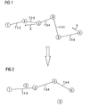
- FIG. 1 shows a schematic representation of communication connections 7.1-2, 7.2-3, 7.3-4, 7.4-5 and 7.5-6 two terminals 1 and 6 in a mobile network over several Intermediate nodes 2 to 5.
- the intermediate node 3 should be mobile in this presentation, for example a mobile base station, which moves to the first terminal 1.
- the second terminal 6 should move and that on the intermediate node 4.
- the movement of the intermediate node 3 to the first terminal 1 and the movement of the second terminal 6 to the intermediate node 4 is by the arrows with the reference numerals 8 and 9 indicated.
- each intermediate node divides 2 to 5 of its Successor node (Next-Hop) or the neighboring terminal 1 or 6 the own receive resource with the predecessor node.
- the nodes measure at regular and cyclical intervals on the receiving resources of their predecessor nodes at least a quantity that characterizes the quality of the message transmission, for example the signal-to-noise ratio or the bit error rate, and share the measurement result with the associated one Predecessor node with. This message may be omitted, if the measurement result is a receipt under a fixed minimum threshold.
- the intermediate node 3 approaches locally to the first terminal 1 on. Analogously, the second terminal 6 approaches the intermediate node 4 on. This is symbolized by the arrows 8 and 9.
- the intermediate node 2 divides the terminal 1 its reception resource from the direction of intermediate node 3 with. It For example, the frequency and time slot of the Connection 7.2-3 between the intermediate node 2 and the intermediate node 3 transmitted to the terminal 1. Besides, shares the intermediate node 2 the intermediate node 3 its receiving resource from the direction of the terminal 1 with, so for example frequency and time slot of connection 7.1-2.
- the terminal 1 measures regularly on the receiving resource notified to it, that is, on the connection 7.2-3, the reception, So for example the signal-to-noise ratio, and sends its results to the intermediate node 3. Accordingly measures the intermediate node 3 regularly on the communicated to him Receive resource, that is on the connection 7.1-2 the Receive and send its results to the intermediate node Second
- the intermediate node 2 receives from the intermediate node. 3 a measurement result and he compares this with his own Measurements on reception on the connection 7.1-2.
- the intermediate node 2 determines in the comparison that the Terminal 1 on the connection 7.2-3 receives better than he himself, so he initiates his own exit or his removal from the compound. The same goes for for comparison with respect to compound 7.1-2.
- the intermediate node 4 measures regularly on the communicated to him Receiving resource, that is on the connection 7.5-6, the reception, for example the signal-to-noise ratio, and sends its results to the intermediate node 5. Accordingly also measures the terminal 6 regularly on the communicated to him Receiving resource, that is on connection 7.4-5, the reception and also sends its results to the intermediate node 5th
- the intermediate node 5 determines in the comparison that the Intermediate node 4 on connection 7.5-6 receives better than he himself, he initiates his own exit or his removal from the compound. The same applies to the comparison with respect to compound 7.4-5.
- FIG. 2 shows the new communication connections of FIG both terminals 1 and 6 after the new procedure is applied has been.
- the first terminal 1 has a new connection 7.1-3 to the intermediate node 3.
- the compounds 7.1-2 and 7.2-3 ( Figure 1) to the intermediate node 2 were separated.
- the second terminal 6 has a new connection 7.4-6 to Intermediate node 4 on.
- Even the now unfavorable Compounds 7.4-5 and 7.5-6 ( Figure 1) were separated.
- the for communication unused or no longer necessary Intermediate nodes 2 and 5 are for the sake of clarity nevertheless shown in FIG. Through this "taking out" of two intermediate nodes 2 and 5, on the one hand, the route length be shortened between the two terminals 1 and 6 and by taking out intermediate nodes can also Electricity can be saved.
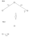
- FIG. 3 shows a schematic representation of the communication connections 7.1-2 and 7.2-6 of two terminals 1 and 6 in a mobile network via an intermediate node 2.
- the second terminal 6 moves to the first terminal 1. This is symbolized by the arrow with the reference numeral 9.
- each component of the communication link so the intermediate node 2 and the terminals 1 and 6, the own receiving resource or the quality of the received signal and shares the result with the neighboring terminal 1 and 6 or the intermediate node 2 with. For example, this determines Intermediate node 2, the field strength of the signal and transmitted the result the first terminal 1 and the second terminal 6.
- the terminals 1 and 6 determine the field strength of Signals and transmit the result to the intermediate node. 2
- the intermediate node 2 sets a procedure in progress, which causes the two terminals 1 and 6 to enter a new connection with each other.
Landscapes
- Engineering & Computer Science (AREA)
- Computer Networks & Wireless Communication (AREA)
- Signal Processing (AREA)
- Mobile Radio Communication Systems (AREA)
- Data Exchanges In Wide-Area Networks (AREA)
Applications Claiming Priority (2)
| Application Number | Priority Date | Filing Date | Title |
|---|---|---|---|
| DE10354943 | 2003-11-25 | ||
| DE10354943A DE10354943B4 (de) | 2003-11-25 | 2003-11-25 | Verfahren zum Betrieb einer Kommunikationsstrecke zwischen zumindest zwei Kommunikatonsendgeräten |
Publications (3)
| Publication Number | Publication Date |
|---|---|
| EP1536600A2 true EP1536600A2 (fr) | 2005-06-01 |
| EP1536600A3 EP1536600A3 (fr) | 2005-11-09 |
| EP1536600B1 EP1536600B1 (fr) | 2012-06-06 |
Family
ID=34442282
Family Applications (1)
| Application Number | Title | Priority Date | Filing Date |
|---|---|---|---|
| EP04023815A Expired - Lifetime EP1536600B1 (fr) | 2003-11-25 | 2004-10-06 | Méthode de mise en oeuvre d'une voie de communication entre au moins deux dispositifs de communication |
Country Status (3)
| Country | Link |
|---|---|
| US (1) | US7443820B2 (fr) |
| EP (1) | EP1536600B1 (fr) |
| DE (1) | DE10354943B4 (fr) |
Cited By (2)
| Publication number | Priority date | Publication date | Assignee | Title |
|---|---|---|---|---|
| KR100823380B1 (ko) | 2005-06-17 | 2008-04-17 | 후지쯔 가부시끼가이샤 | 통신 시스템 |
| KR100859930B1 (ko) | 2005-06-17 | 2008-09-23 | 후지쯔 가부시끼가이샤 | 통신 시스템 |
Families Citing this family (2)
| Publication number | Priority date | Publication date | Assignee | Title |
|---|---|---|---|---|
| US7631021B2 (en) * | 2005-03-25 | 2009-12-08 | Netapp, Inc. | Apparatus and method for data replication at an intermediate node |
| JP5849851B2 (ja) * | 2012-04-26 | 2016-02-03 | 富士通株式会社 | 無線端末装置、無線通信システム及び無線端末装置制御方法 |
Family Cites Families (8)
| Publication number | Priority date | Publication date | Assignee | Title |
|---|---|---|---|---|
| CA2356947A1 (fr) * | 1998-12-23 | 2000-07-06 | Nokia Wireless Routers, Inc. | Plan d'acheminement unifie pour l'interconnexion de reseaux ad hoc |
| JP3149928B2 (ja) * | 1999-02-12 | 2001-03-26 | 日本電気株式会社 | 無線パケット通信システムのチャネル選択方法及びチャネル選択装置 |
| EP1080596B1 (fr) * | 1999-03-09 | 2003-06-04 | Salbu Research and Development (Proprietary) Limited | Acheminement dans un reseau a stations multiples |
| EP1517477B1 (fr) * | 1999-06-23 | 2007-01-24 | Sony Deutschland GmbH | Commande de puissance de transmission dans un réseau sans fil utilisant un mode de traffic direct |
| GB9930366D0 (en) * | 1999-12-22 | 2000-02-09 | Nokia Networks Oy | Signal routing |
| US6539232B2 (en) * | 2000-06-10 | 2003-03-25 | Telcontar | Method and system for connecting mobile users based on degree of separation |
| DE10214629A1 (de) * | 2002-04-02 | 2003-10-16 | Philips Intellectual Property | Verfahren zum Organisieren der Topologie eines Netzwerkes mit einer Vielzahl von Stationen, die in Cluster gruppiert sind |
| US6894985B2 (en) * | 2002-08-05 | 2005-05-17 | Harris Corporation | Monitoring link quality in a mobile ad hoc network |
-
2003
- 2003-11-25 DE DE10354943A patent/DE10354943B4/de not_active Expired - Fee Related
-
2004
- 2004-10-06 EP EP04023815A patent/EP1536600B1/fr not_active Expired - Lifetime
- 2004-11-24 US US10/997,242 patent/US7443820B2/en not_active Expired - Fee Related
Cited By (2)
| Publication number | Priority date | Publication date | Assignee | Title |
|---|---|---|---|---|
| KR100823380B1 (ko) | 2005-06-17 | 2008-04-17 | 후지쯔 가부시끼가이샤 | 통신 시스템 |
| KR100859930B1 (ko) | 2005-06-17 | 2008-09-23 | 후지쯔 가부시끼가이샤 | 통신 시스템 |
Also Published As
| Publication number | Publication date |
|---|---|
| EP1536600A3 (fr) | 2005-11-09 |
| DE10354943B4 (de) | 2008-08-28 |
| US7443820B2 (en) | 2008-10-28 |
| DE10354943A1 (de) | 2005-06-30 |
| EP1536600B1 (fr) | 2012-06-06 |
| US20050141458A1 (en) | 2005-06-30 |
Similar Documents
| Publication | Publication Date | Title |
|---|---|---|
| DE602005001250T2 (de) | Paketübertragungssystem, drahtlose Basisstation und Verfahren zur Routen-Optimierung für die Paketübertragung | |
| DE60004771T2 (de) | Verfahren und Einrichtung zur Kommunikationsstabilisierung in einem mobilen Kommunikationssystem | |
| DE69838562T2 (de) | Leistungsanpassung in einem mehrstationen-netzwerk | |
| EP0996257B1 (fr) | Réseau avec des terminaux-pont pour la transmission de données entre plusieurs sous-réseaux | |
| DE69935131T2 (de) | Senderleistungssteuerung für Netzwerkgeräte in einem drahtlosen Netzwerk | |
| DE60315623T2 (de) | Verfahren, computerlesbares Medium und Knoten zum Auswählen zuverlässiger Strecken zwischen Knoten in einem ad-hoc-Kommunikationsnetz | |
| DE69025353T2 (de) | Kommunikationssystem für Datenübertragung über einen Zeitduplex-Frequenzkanal | |
| DE60123398T2 (de) | Verfahren zur Datenkommunikation im selbstorganisierenden Netz mit Enscheidungsvorrichtung | |
| DE602005004744T2 (de) | Kontrollvorrichtung, mobiles Endgerät und Kommunikationskontrollverfahren | |
| DE102015111405A1 (de) | Beacon und Verfahren zum Aufbau und zur Aufrechterhaltung eines Netzwerkes | |
| EP2227920A1 (fr) | Réseau de communication auto-organisé et son procédé de fonctionnement | |
| DE112012005907T5 (de) | Kommunikationssystem, Kommunikationsendgerät und Kommunikationsverfahren | |
| WO2008125516A1 (fr) | Procédé de détermination d'une valeur de distance de trajectoire et noeud réseau | |
| DE69935271T2 (de) | Verfahren, Gerät, und Steuergerät zur drahtlosen Kommunikation | |
| DE112006002112T5 (de) | Verfahren und Vorrichtung zum Weiterleiten von Anrufen | |
| DE19848342A1 (de) | Lokales Netzwerk mit einem Brücken-Terminal zur Übertragung von Daten zwischen mehreren Sub-Netzwerken und zur Schleifendetektion | |
| EP2365643B1 (fr) | Système de station radio pour un réseau sans fil | |
| DE10044994A1 (de) | Neukonfigurierung eines Adhoc-Netzwerks | |
| DE60008979T2 (de) | Verfahren zur Erhaltung einer Kommunikationsverbindung in drahtlosen Netzwerkgruppen | |
| EP1536600B1 (fr) | Méthode de mise en oeuvre d'une voie de communication entre au moins deux dispositifs de communication | |
| DE19848341A1 (de) | Automatische Konfigurierung eines Brücken-Terminals zur Übertragung von Daten zwischen mehreren Sub-Netzwerken in einem lokalen Netzwerk | |
| EP3525476B1 (fr) | Procede de determination de topologie d'un site de communication mobile et un site de communication mobile correspondant | |
| DE10107816A1 (de) | Netzwerk mit mehreren über Brücken-Terminals verbindbaren Sub-Netzwerken | |
| EP1672954A2 (fr) | Dispositif et procédé destiné à la saisie d'affichages de compteurs | |
| DE2256081C2 (de) | Fernmeldeanlage mit Verbindungsverkehr zwischen ortsfesten und beweglichen Teilnehmerstellen über Relaisstationen |
Legal Events
| Date | Code | Title | Description |
|---|---|---|---|
| PUAI | Public reference made under article 153(3) epc to a published international application that has entered the european phase |
Free format text: ORIGINAL CODE: 0009012 |
|
| AK | Designated contracting states |
Kind code of ref document: A2 Designated state(s): AT BE BG CH CY CZ DE DK EE ES FI FR GB GR HU IE IT LI LU MC NL PL PT RO SE SI SK TR |
|
| AX | Request for extension of the european patent |
Extension state: AL HR LT LV MK |
|
| PUAL | Search report despatched |
Free format text: ORIGINAL CODE: 0009013 |
|
| AK | Designated contracting states |
Kind code of ref document: A3 Designated state(s): AT BE BG CH CY CZ DE DK EE ES FI FR GB GR HU IE IT LI LU MC NL PL PT RO SE SI SK TR |
|
| AX | Request for extension of the european patent |
Extension state: AL HR LT LV MK |
|
| 17P | Request for examination filed |
Effective date: 20060421 |
|
| AKX | Designation fees paid |
Designated state(s): DE FR GB |
|
| REG | Reference to a national code |
Ref country code: DE Ref legal event code: R079 Ref document number: 502004013554 Country of ref document: DE Free format text: PREVIOUS MAIN CLASS: H04L0012560000 Ipc: H04W0040120000 |
|
| GRAP | Despatch of communication of intention to grant a patent |
Free format text: ORIGINAL CODE: EPIDOSNIGR1 |
|
| RIC1 | Information provided on ipc code assigned before grant |
Ipc: H04W 40/12 20090101AFI20111128BHEP Ipc: H04L 12/56 20060101ALN20111128BHEP |
|
| GRAS | Grant fee paid |
Free format text: ORIGINAL CODE: EPIDOSNIGR3 |
|
| GRAA | (expected) grant |
Free format text: ORIGINAL CODE: 0009210 |
|
| AK | Designated contracting states |
Kind code of ref document: B1 Designated state(s): DE FR GB |
|
| REG | Reference to a national code |
Ref country code: GB Ref legal event code: FG4D Free format text: NOT ENGLISH |
|
| REG | Reference to a national code |
Ref country code: DE Ref legal event code: R096 Ref document number: 502004013554 Country of ref document: DE Effective date: 20120802 |
|
| RAP2 | Party data changed (patent owner data changed or rights of a patent transferred) |
Owner name: SIEMENS AKTIENGESELLSCHAFT |
|
| PLBE | No opposition filed within time limit |
Free format text: ORIGINAL CODE: 0009261 |
|
| STAA | Information on the status of an ep patent application or granted ep patent |
Free format text: STATUS: NO OPPOSITION FILED WITHIN TIME LIMIT |
|
| 26N | No opposition filed |
Effective date: 20130307 |
|
| REG | Reference to a national code |
Ref country code: DE Ref legal event code: R097 Ref document number: 502004013554 Country of ref document: DE Effective date: 20130307 |
|
| REG | Reference to a national code |
Ref country code: FR Ref legal event code: PLFP Year of fee payment: 12 |
|
| PGFP | Annual fee paid to national office [announced via postgrant information from national office to epo] |
Ref country code: GB Payment date: 20151005 Year of fee payment: 12 |
|
| PGFP | Annual fee paid to national office [announced via postgrant information from national office to epo] |
Ref country code: FR Payment date: 20151016 Year of fee payment: 12 |
|
| PGFP | Annual fee paid to national office [announced via postgrant information from national office to epo] |
Ref country code: DE Payment date: 20151218 Year of fee payment: 12 |
|
| REG | Reference to a national code |
Ref country code: DE Ref legal event code: R119 Ref document number: 502004013554 Country of ref document: DE |
|
| GBPC | Gb: european patent ceased through non-payment of renewal fee |
Effective date: 20161006 |
|
| REG | Reference to a national code |
Ref country code: FR Ref legal event code: ST Effective date: 20170630 |
|
| PG25 | Lapsed in a contracting state [announced via postgrant information from national office to epo] |
Ref country code: DE Free format text: LAPSE BECAUSE OF NON-PAYMENT OF DUE FEES Effective date: 20170503 Ref country code: FR Free format text: LAPSE BECAUSE OF NON-PAYMENT OF DUE FEES Effective date: 20161102 Ref country code: GB Free format text: LAPSE BECAUSE OF NON-PAYMENT OF DUE FEES Effective date: 20161006 |