EP1536610A2 - Method for data transmission in a communication system - Google Patents
Method for data transmission in a communication system Download PDFInfo
- Publication number
- EP1536610A2 EP1536610A2 EP04104643A EP04104643A EP1536610A2 EP 1536610 A2 EP1536610 A2 EP 1536610A2 EP 04104643 A EP04104643 A EP 04104643A EP 04104643 A EP04104643 A EP 04104643A EP 1536610 A2 EP1536610 A2 EP 1536610A2
- Authority
- EP
- European Patent Office
- Prior art keywords
- connection
- communication
- node
- unit
- dmc
- Prior art date
- Legal status (The legal status is an assumption and is not a legal conclusion. Google has not performed a legal analysis and makes no representation as to the accuracy of the status listed.)
- Granted
Links
Images





Classifications
-
- H—ELECTRICITY
- H04—ELECTRIC COMMUNICATION TECHNIQUE
- H04L—TRANSMISSION OF DIGITAL INFORMATION, e.g. TELEGRAPHIC COMMUNICATION
- H04L65/00—Network arrangements, protocols or services for supporting real-time applications in data packet communication
- H04L65/1066—Session management
- H04L65/1069—Session establishment or de-establishment
-
- H—ELECTRICITY
- H04—ELECTRIC COMMUNICATION TECHNIQUE
- H04L—TRANSMISSION OF DIGITAL INFORMATION, e.g. TELEGRAPHIC COMMUNICATION
- H04L65/00—Network arrangements, protocols or services for supporting real-time applications in data packet communication
- H04L65/80—Responding to QoS
-
- H—ELECTRICITY
- H04—ELECTRIC COMMUNICATION TECHNIQUE
- H04M—TELEPHONIC COMMUNICATION
- H04M7/00—Arrangements for interconnection between switching centres
- H04M7/006—Networks other than PSTN/ISDN providing telephone service, e.g. Voice over Internet Protocol (VoIP), including next generation networks with a packet-switched transport layer
-
- H—ELECTRICITY
- H04—ELECTRIC COMMUNICATION TECHNIQUE
- H04M—TELEPHONIC COMMUNICATION
- H04M7/00—Arrangements for interconnection between switching centres
- H04M7/009—Arrangements for interconnection between switching centres in systems involving PBX or KTS networks
-
- H—ELECTRICITY
- H04—ELECTRIC COMMUNICATION TECHNIQUE
- H04M—TELEPHONIC COMMUNICATION
- H04M7/00—Arrangements for interconnection between switching centres
- H04M7/12—Arrangements for interconnection between switching centres for working between exchanges having different types of switching equipment, e.g. power-driven and step by step or decimal and non-decimal
- H04M7/1205—Arrangements for interconnection between switching centres for working between exchanges having different types of switching equipment, e.g. power-driven and step by step or decimal and non-decimal where the types of switching equipement comprises PSTN/ISDN equipment and switching equipment of networks other than PSTN/ISDN, e.g. Internet Protocol networks
- H04M7/1245—Arrangements for interconnection between switching centres for working between exchanges having different types of switching equipment, e.g. power-driven and step by step or decimal and non-decimal where the types of switching equipement comprises PSTN/ISDN equipment and switching equipment of networks other than PSTN/ISDN, e.g. Internet Protocol networks where a network other than PSTN/ISDN interconnects two PSTN/ISDN networks
-
- H—ELECTRICITY
- H04—ELECTRIC COMMUNICATION TECHNIQUE
- H04Q—SELECTING
- H04Q3/00—Selecting arrangements
- H04Q3/0016—Arrangements providing connection between exchanges
-
- H—ELECTRICITY
- H04—ELECTRIC COMMUNICATION TECHNIQUE
- H04Q—SELECTING
- H04Q2213/00—Indexing scheme relating to selecting arrangements in general and for multiplex systems
- H04Q2213/13034—A/D conversion, code compression/expansion
-
- H—ELECTRICITY
- H04—ELECTRIC COMMUNICATION TECHNIQUE
- H04Q—SELECTING
- H04Q2213/00—Indexing scheme relating to selecting arrangements in general and for multiplex systems
- H04Q2213/13196—Connection circuit/link/trunk/junction, bridge, router, gateway
-
- H—ELECTRICITY
- H04—ELECTRIC COMMUNICATION TECHNIQUE
- H04Q—SELECTING
- H04Q2213/00—Indexing scheme relating to selecting arrangements in general and for multiplex systems
- H04Q2213/1322—PBX
-
- H—ELECTRICITY
- H04—ELECTRIC COMMUNICATION TECHNIQUE
- H04Q—SELECTING
- H04Q2213/00—Indexing scheme relating to selecting arrangements in general and for multiplex systems
- H04Q2213/13389—LAN, internet
Definitions
- the invention relates to a method for the transmission of Communication data in a preferably heterogeneous communication system.
- a convergent communication system usually includes at least one communication device with which by corresponding terminal assemblies a connection of both IP communication terminals as well as “classical”, i. according to the circuit-switching principle working communication terminals is possible.
- the communication devices are usually among themselves and with others so-called remote units, which in turn one Contribute to mediation and connection control, connected.
- gateways For conversion between line-oriented and packet-oriented Transmission techniques can be convergent Communication system continues to use so-called gateways become.
- a gateway takes on a conversion between packet-oriented and circuit-oriented transmission techniques and is often between a packet-oriented network and one working according to a circuit-switching method Communication device arranged.
- subscriber modules and / or connection modules the communication facilities and so-called "Remote units" with functions of a gateway.
- node unit For remote units, communication devices as well for facilities, in addition to the aforementioned units as an independent unit on a call setup or are involved in a more general Representation also used the term "node unit".
- Communication unit generally involved in a communication Terminals, e.g. VoIP communication terminals, analogue and portable or cordless telephones, as well Data terminals such as computer systems, mobile digital assistants etc.
- a converged communication system is often through a Structuring is characterized in individual subnetworks, wherein usually every subnetwork through a communication device or managed by a remote unit, which each for the transmission of user or signaling data according to the necessary packet-oriented or circuit-oriented Connection design of the connected communication terminals work according to a different transmission method.
- the object of the invention is to provide means by their use a loss of quality in a transfer of User data between heterogeneous transmission methods reduced becomes.
- the inventive method for transmitting communication data in a communication system between a calling one first communication unit and a called second Communication unit initially sees a structure of a primary connection before.
- This primary compound is going out from the first communication unit via at least one Node unit to the second communication unit constructed, wherein those used in the construction of the primary compound Message addressing data of the primary Connection participating communication units and node units Addressing data is included and with control messages for establishing the primary connection.
- the primary connection is from the first communication unit via at least one node unit to the second Communication unit constructed, with the number of for the primary connection contained node units of the network structure is dependent.
- Using the transmitted addressing data involved in building the primary connection Communication unit is registered an entry node.
- the entry node is defined by the along the primary Connection first necessary conversion of line-oriented to packet-oriented communication data. Of the Exit node is defined by the along the primary Connection last necessary conversion of package-oriented to line-oriented communication data.
- the entry-level node is the first unit with a valid addressing date, i. which is a valid addressing date having first communication unit itself or the first node unit with a valid addressing date.
- a valid one Addressing date is for example the provision of a Communication unit or node unit with a network address, below the communication unit or node unit from a - for example, packet-oriented - network can be addressed.
- a along the primary link arranged last node unit with a valid addressing date or the second Communication unit itself - if it is a valid addressing date has - registered as an exit node.
- last step is the formation of a secondary Connection between the previously registered entry-level nodes and exit nodes via an available in the communication system Network provided.
- the communication data - In particular payload - are then on the secondary Transmitted connection.
- An essential advantage of the method according to the invention is to see that a transmission of communication data via the secondary compound directly, i. without involvement several node units and thus necessary conversions is accomplished.
- the secondary connection takes place doing so for example via a packet-oriented network, resulting in a heterogeneous communication system with both on a circuit-switched and on a packet-oriented basis Transmission equipment having node units a multiple conversion of the user data packets or the User data stream is avoided in which a shortcut on the secondary connection without involving multiple node units is selected.
- Another advantage of the method consists in the choice of the entry or exit node.
- Method is provided that the entry-level node as close as possible to the calling first communication unit and according to the exit node possible is close to the called second communication unit.
- a choice of a packet-oriented transmission method for the secondary connection is multiple conversions along the secondary connection thus avoidable.
- the package-oriented Transmission is without further conversion maintained along the secondary link to the exit node.
- a transmission of communication data for example, in the form of language, is by applying the inventive method a significant improvement the voice quality both at the first and the first call the called second communication unit detectable.
- the feature control is done in an advantageous manner by a respective communication device assigned to the communication unit via signaling data of the primary Connection.
- the method according to the invention for heterogeneous communication systems i. with a line-oriented and a packet-oriented transmission technique, applied.
- the primary connection is on a connecting section between two node units or between a node unit and a communication unit depending the connection type of the node units or communication units.
- the connection type of the node unit or communication unit is either circuit-oriented or packet-oriented, so that between heterogeneous node units a conversion between line-oriented communication data or communication data packets is required.
- Using the method according to the invention is the quality improvement the transmitted communication data in case a heterogeneous communication system considerably.
- a node unit involved in setting up the primary connection First, a check is made to see if the more Construction of the secondary connection including this Node unit is allowed.
- the configuration data are for example held at the respective node unit.
- further node units in the Primary connection included is the secondary connection provided in the form of two connecting sections, wherein the first connection section at the node unit as Exit node ends and the second section on one after the node unit arranged entry node begins.
- a division of the secondary Connection performed in other connecting sections.
- FIG. 1 shows a communication system CSY with a section of functional components essential to the invention.
- An essential component of the communication system CSY are node units in the form of a first communication device PBX1, a second communication device PBX2 and a third communication device PBX3.
- the communication devices PBX1, PBX2, PBX3 work internally according to a time-slot-oriented switching principle - often referred to in the professional world as »Time Division Multiplex «, TDM designated - and therefore have a corresponding respective switching network TDM1, TDM2, TDM3.
- the communication devices PBX1, PBX, PBX3 are respectively with a circuit switching switching network TDM1, TDM2, TDM3 designed and in each case and with each other with a package-oriented Network connected.
- the first and the second communication device PBX1, PBX2 are with a first packet-oriented network segment LAN1 connected.
- the first packet-oriented network segment LAN1 is alternatively as Intranet, company network, as domain of a larger network or even part of a worldwide network Data network such as the so-called World Wide Web, WWW, designed.
- the third communication device PBX3 is at a second packet-oriented network segment LAN2 connected.
- the configuration of the second packet-oriented network segment LAN2 is the same for the first packet-oriented network segment LAN1 said.
- the first communication device PBX1 is connected via a connection board TB1 with the first packet-oriented network segment LAN1 connected.
- the second communication device PBX2 via a second connection module TB2 with the first packet-oriented network segment LAN1 connected.
- connection assemblies TB1, TB2 of the corresponding communication devices PBX1, PBX2 serve an exchange of packet-oriented Communication data between the two communication devices PBX1, PBX2 via the packet-oriented Network segment LAN1 and count as the communication devices PBX1, PBX2, PBX3 to the category of node units.
- the second communication device PBX2 is the third Communication device PBX3 via a trunk line TRK connected. Unlike a connection via the connection modules TB1, TB2 over the first packet-oriented Network segment LAN1 is on a transmission over the trunk line TRK between the second communication device PBX2 and the third communication device PBX3 a line-oriented Cross connection between both communication devices PBX2, PBX3 provided.
- a first VoIP communication terminal IPP1 is over the first packet-oriented network segment LAN1 and via a first subscriber line module SLM1.1 the first communication device PBX1 having the first communication direction PBX1 connected.
- a second VoIP communication terminal IPP2 is over the first packet-oriented network segment LAN1 and one second subscriber line subassembly SLM1.2 the first communication device PBX1 with the first communication device PBX1 connected.
- a third VoIP communication terminal IPP3 over the first packet-oriented network segment LAN1 with a second subscriber line module SLM2 with the second communication device PBX2 connected.
- Another, fourth VoIP communication terminal IPP4 is via the second packet-oriented network segment LAN2 with a third subscriber line module SLM3 the third Communication device PBX3 connected.
- Another communication terminal ANP is with the third Communication device PBX3 connected line-oriented. It is in this communication terminal ANP example to an analog telephone.
- the subscriber line modules SLM1.1, SLM1.2, SLM2, SLM3 lead a bidirectional conversion between a direction the VoIP communication terminals take place packet-oriented Transmission and one inside the communication devices PBX1, PBX2, PBX3 conduction-oriented Transmission by.
- the subscriber line modules SLM1.1, SLM1.2 are line-oriented with the first switching field TDM1 inside the first communication device PBX1 connected. In appropriate Way are the second subscriber line module SLM2 with the second switching matrix TDM2 as part of the second communication device PBX2 and the third subscriber line module SLM3 with the third switching matrix TDM3 the third communication device PBX3 internally connected.
- the line-oriented communication terminal ANP is a conversion between previously described packet-oriented and circuit-switched communication data not provided.
- the third communication device PBX3 also via a - Not shown - subscriber line module takes place, is a direct one in favor of a comprehensible representation - i. without provision of a conversion - line - oriented Connection of the communication device ANP with the third Coupling field TDM3 shown in the drawing.
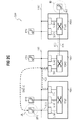
- Fig. 2A shows a structure diagram for schematic representation a transmission of communication data in a first Application.
- this first use case becomes a primary communication connection between a calling one Subscriber A at the first communication terminal IPP1 to a called subscriber B at the third VoIP communication terminal IPP3 built.
- the primary communication connection is based on the first VoIP communication terminal IPP1 via a first connection path RA1 to the first subscriber line module SLM1.1 the first communication device PBX1 constructed.
- the first subscriber line module SLM1.1 packet-oriented Communication data of the first VoIP communication terminal IPP1 in line-oriented communication data converted and a first switching matrix TDM1 the supplied to the first communication device PBX1.
- the first communication device PBX1 becomes an intermediary due to the communication data Communication participants determined and accordingly established further connection paths.
- the third VoIP communication terminal to be called is called from another, the second communication device PBX2 managed.
- the coupling field TDM1 After leaving the coupling field TDM1 will connect the communication on one second connection path RA2, via the first connection module TB1 and the first packet-oriented network segment LAN1, led to the second communication device PBX2.
- the second connection path RA2 is via a second Connection module TB2 of the second communication device PBX2, again with bidirectional conversion between packet-oriented and circuit-switched communication data he follows. After this conversion, the connection path becomes further led to the second switching matrix TDM2, in which a line-oriented exchange to the second Subscriber module SLM2 takes place.
- the second participant module SLM2 become the line-oriented communication data again converted into packet-oriented communication data and via the third connection path RA3 or the first packet-oriented network segment LAN1 to the third VoIP communication terminal IPP3 and thus to the called subscriber B through.
- the routing or conversion of the so far in the direction from the calling to the called party A, B described Communication data is in the reverse direction in an analogous way.
- connection paths RA1, RA2, RA3 is a user data exchange between the calling party A and the called party Subscriber B on this connection path.
- On the primary connection path be communication data - including the Payload - a total of six times between a packet-oriented and a wire-oriented format.
- DMC Direct Media Connection
- the SIP standard the H.323 standard or other protocols for providing a transmission of communication data in packet-oriented networks - »Voice over IP «, or VoIP - approachable.
- SIP Session Initiation Protocol
- IETF Internet Engineering Task Force
- the H.323 standard is an international ITU-T standard (International Telecommunication Union - Telecommunication Standardization Sector) for voice, data and video communication about packet-oriented networks that require interoperability the manufacturer products with each other guaranteed.
- ITU-T International Telecommunication Union - Telecommunication Standardization Sector
- the secondary compound DMC-A is in a general case from as close as possible on the part of the calling subscriber A lying node unit or communication unit to a as close as possible to pages of called party B. Communication unit or node unit out.
- Subscriber A, B associated communication terminals IPP1, IPP3 over a valid addressing date, i.e., they are from the first packet-oriented network segment LAN1 of Any communication partner aware of their Network address accessible.
- the secondary connection DMC-A After the later to be described in detail construction of the secondary connection DMC-A send and receive the endpoints - i. the first and the third VoIP communication terminal IPP1, IPP3 - this secondary connection DMC-A user data exclusively via this secondary compound DMC-A, while on the primary connection involving the first and second communication means PBX1, PBX2 and the connection paths RA1, RA2, RA3 no longer transmit user data become.
- this primary connection will be in progress maintain the secondary connection DMC-A, if necessary, e.g. one initiated by the calling party Consultation, agency services or features the communication facilities PBX1, PBX2 claim to be able to.
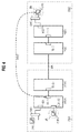
- Fig . 2B shows a structure diagram for the schematic representation of a transmission of communication data in a second application.
- This second application differs from the aforementioned first use case essentially by the fact that the called party B this time is located at the fourth VoIP communication terminal IPP4 controlled by the third communication device PBX3.
- the third communication device is PBX3 with the second packet-oriented network segment LAN2 connected, it is therefore due to this logical segmentation and respective management by the communication devices PBX1, PBX2, PBX3 no packet-oriented connection between the third communication device PBX3 and the first communication device PBX1 via a common - Not shown - provided network.
- a third connection path RB3 is done in contrast to the first application over the trunk line TRK and thus in a line-oriented Way to the third switching matrix TDM3 of the third Communication device PBX3.
- the primary connection is ongoing in the further via a fourth connection path RB4 of the third subscriber line module SLM3 on the second packet-oriented network segment LAN2 to the fourth VoIP communication terminal IPP4.
- LAN1, LAN2 are these network segments LAN1, LAN2 not physically separated.
- the Division into individual network segments or domains corresponds an administrative allocation to the individual communication devices PBX1, PBX2, PBX3 where below At any time it is assumed that one without participation the communication devices PBX1, PBX2, PBX3 taking place Connection between communication endpoints between the different network segments LAN1, LAN2 via a common - Not shown - build network is.
- the primary compound described above secondary connection DMC-B is due to the packet-oriented Connection of the participants VoIP communication terminals IPP1, IPP4 directly between the mentioned communication terminals IPP1, IPP4.
- Fig. 2C shows a structural diagram for schematic representation a transmission of communication data in a third Application.
- the called is Subscriber B is located at a communication terminal ANP, which does not have a valid addressing date has, the communication terminal ANP of the called party
- B is an analog phone.
- the secondary compound DMC-C goes in this case again from the calling party A, but ends at the second connection board TB2, i. the node unit, which along the primary connection closest to the one called Subscriber B lying node unit with a valid Addressing date is.
- the built up before the secondary connection and parallel to this held primary connection is made from the calling Subscriber A via his assigned VoIP communication terminal IPP1 via a first connection path RC1 the first subscriber line module SLM1.1 the first communication device PBX1, via its first switching matrix TDM1 to the first connection module TB1 and continue via a second connection path RC2 from the first connection module TB1 to the second connection module TB2 of the second Communication device PBX2, from where they over the second switching matrix TDM2 on the trunk line TRK on the third switching matrix TDM3 of the third communication device PBX3 and finally via a connecting line the communication terminal ANP achieved.
- the communication devices PBX1, PBX2, PBX3 and their Local loop modules SLM1.1, SLM1.2, SLM2, SLM3 and their Connection modules TB1, TB2 are in accordance with the language this description as node units with a to consider the valid addressing date, i.e., each circuit-oriented packet-oriented-converting node unit is characterized by a valid addressing date.
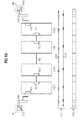
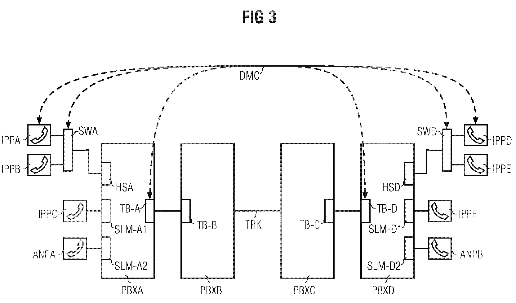
- Fig. 3 shows a communication system with respect to the previous figures changed structure to the schematic Illustration of an efficient design of a secondary Connection.
- the communication system comprises several communication units, in detail, a first VoIP communication terminal IPPA, a second VoIP communication terminal IPPB, a third VoIP communication terminal IPPC, a fourth VoIP communication terminal IPPD, a fifth VoIP communication terminal IPPE, a sixth VoIP communication terminal IPPF and a first communication terminal ANPA and a second one Communication terminal ANPB.
- the last-mentioned communication terminals ANPA, ANPB do not have a valid addressing date and are for example as analog telephones designed.
- the communication system further comprises four partially with each other connected communication devices PBXA, PBXB, PBXC, PBXD.
- the communication devices PBXA, PBXB, PBXC, PBXD operate on a timeslot-oriented
- the principle of mediation - in the professional world often as »Time Division Multiplex «, TDM denotes - and dispose accordingly via a corresponding switching network.
- TDM time Division Multiplex
- the first and the second VoIP communication terminal IPPA, IPPB are via a first switch SWA with the first Communication device connected.
- the fourth and the fifth VoIP communication terminal IPPD, IPPE via a second switch SWD with the fourth communication device PBXD connected.
- the two switch units SWA, SWD each have one valid addressing date and are also as node units consider.
- the connection of the first switch SWA takes place with the associated first communication device PBXA for example via a - not shown - package-oriented Network with one in the first communication device PBXA integrated host switch HSA.
- the connection of the second switch SWD with the fourth communication device PBXD via a second Host Switch HSD.
- a e.g. packet-oriented cross-connection between the first and the second communication device PBXA, PBXB takes place via the first connection module TB-A or via the second Connection assembly TB-B, these connection assemblies TB-A, TB-B in the respective communication facilities PBXA, PBXB are integrated.
- a third connection module TB-C of the third communication device PBXC connects them to a fourth interconnect board TB-D of the fourth communication device PBXD.
- the two switch units SWA, SWD and their connected Host Switch HSA, HSD are like the connection boards TB-A, TB-B, TB-C, TB-D as node units in the sense of before to look at.
- FIG. 3 several possible embodiments of a secondary Connection DMC between the first VoIP communication terminal IPPA and the fourth VoIP communication terminal IPPD shown.
- IPPD IP-to-Network Interface
- the determination of the entry and exit nodes based on the valid Addressing data occurs during connection setup the primary connection.
- the secondary connection advantageously proceeds from an exit node - i. from the called communication unit or one arranged along the primary link last node unit with a valid addressing date - to the entry node - i. to the calling communication unit or to one arranged along the primary link first node unit with a valid addressing date.
- any mixed communication systems arise while in Fig. 3 different ways of Span of the secondary compound DMC.
- the others in Fig. 3 illustrated embodiments of FIG. 3 relate to cases in those outer communication units and node units do not have a valid address date in which the Span of the secondary connection DMC so accordingly is smaller.
- the secondary connection DMC starts at the first switch SWA, which is thus an entry-level node. Accordingly, the ends secondary connection DMC on the fourth switch SWD - exit node - in the event that the called fifth VoIP communication terminal IPPE does not have a valid addressing date features.
- the VoIP communication terminals IPPA, IPPB, IPPC, IPPD, IPPE, IPPF each have a valid addressing date.
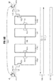
- FIG. 4 shows a structure diagram for the schematic representation of a transmission of communication data in a communication system arranged in several subnetworks.
- the structure diagram of FIG. 4 uses the functional components known from FIG. 3 for the further description.
- DM1 the communication system in a first domain DM1 as well as in a second domain DM2 is structured.
- the domains correspond to DM1, DM2 doing a logical segmentation of the communication system, as in the previous description in a physical expression also as a network segment were designated.
- the following is a connection between a calling Subscriber A on the first communication terminal ANPA and a called party B on the fifth VoIP communication terminal IPPE.
- the Primary connection is a secondary DMC connection between the first connection assembly TB-A of the first communication device PBXA and the fifth VoIP communication terminal IPPE.
- the first connection module TB-A corresponds to the for calling subscriber A nearest node unit with a valid addressing date.
- the communication terminal ANPA itself is, as already mentioned, an analog telephone and therefore does not have a valid addressing date or not about the possibility of a network connection.
- the secondary connection DMC cross-domain is configured, i. from a node unit of the first one Domain DM1 to a communication unit of the second domain DM2.
- FIG. 5 shows the communication system known from FIG. 4 in a second embodiment. While the called subscriber B is once again located at the fifth VoIP communication terminal IPPE, this time the calling subscriber is located at the first VoIP communication terminal IPPA.
- the secondary connection is not directly between the calling subscriber A and the called subscriber B set up can be there because of certain restrictions in the communication system no direct cross-domain connections between the first domain DM1 and the second domain DM2 may or may take place.
- Each node unit checks if the construction of the secondary Connection permissible using this node unit is. In the present case is at the second communication device PBXB as a domain boundary notes that the secondary Do not connect beyond domain boundaries may.
- connection is established in the primary connection "Entry node” including valid addressing data again deleted, thus in subsequent domains again an entry node can be determined.
- the secondary compound is divided into two connecting sections DMC1, DMC2, wherein the first connection section DMC1 between the first VoIP communication terminal IPPA and preceding the second communication unit PBXB Node unit, i. the second connection assembly TB-B, is trained. Consequently, this node unit TB-B also becomes designated as exit node.
- LCR configuration too significant embodiment between the second and the third communication device PBXB, PBXC.
- LCR is one on network specific Rules based connection management according to customer individual Needs such as Voice quality, subscriber-dependent security devices, Cost reasons, bandwidth and / or Availability provided.
- the second connection section DMC2 of the secondary connection begins at the third communication device PBXC following node unit, thus the third connection module TB-C. Consequently, this node unit TB-C also becomes referred to as the entry node. From this entry-level node, the third connection module TB-C, the second takes place Connection section DMC2 of the secondary connection to the called Subscriber B at its fifth VoIP communication terminal IPPA.
- Fig. 6A is a flowchart showing an exchange of control messages for forming a primary connection.
- a communication connection between a calling party A and a called party Participant B will be established.
- the calling subscriber A is at the first VoIP communication terminal IPPA, the one called Subscriber on the fourth communication terminal IPPD localized.
- the signaling data SGN M support a controller the communication link and a control of features.
- Integrated Services Digital Network In a circuit-oriented ISDN communication system - "Integrated Services Digital Network" - become user data PLD_M via one or more base channels or B channels transfer.
- the signaling information SGN_M is in an ISDN communication system via a so-called Transmit D-channel.
- Destination addresses provide data packets necessary to control the payload and Signaling data PLD_M, SGN_M via the - not shown - to transmit packet-oriented network.
- At the exit from the packet-oriented network becomes in the communication facilities PBXA, PBXB, PBXC, PBXD from the data packets again a continuous data stream composed.
- the procedure begins with the input of an election information or telephone number at the first VoIP communication terminal IPPA by the calling subscriber A. After entering the complete Dialing information is provided by the calling VoIP communication terminal IPPA sent a connection request message SETP, the in the further up to the called VoIP communication terminal IPPD is forwarded.
- This transfer or "transit" the connection request message SETP is accompanied with a modification and enrichment of in the connection request message SETP contained data which drawn by arrows in combination with horizontal lines in the amount of the respective data of the connection request message SETP modifying node unit shown is.
- connection request message SETP is after generation through the first VoIP communication terminal IPPA from the first communication device PBXA received and the second communication device PBXB forwarded. at each propagation of the connection request message SETP is based on configuration data from the primary Connection involved node units, in this case the first communication unit PBXA or the first connection module TB-A checks whether the current node unit a valid addressing date for a possible having secondary connection establishment. Additionally - cf. Fig. 7A to be described later is performed in each node unit a check whether the respective current node unit is a domain boundary.
- the second communication device PBXB initiates upon receipt the connection request message SETP this to the third Communication device PBXC by way of trunking TRK continues.
- the connection request message SETP passes the third communication device PBXC this - following the mentioned modification of the included Data - via the fourth communication device PBXD to the called VoIP communication terminal IPPD on.
- connection request message SETP is the part of the fourth VoIP communication terminal IPPD
- IPPD Upon receipt of the connection request message SETP is the part of the fourth VoIP communication terminal IPPD
- a connection confirmation message CNCT via the fourth switch SWD to the fourth Communication device PBXD and from this to the third Communication device PBXC sent, from which these Connection confirmation message CNCT via the third communication device PBXC over the trunk line TRK to the second communication device PBXB - in one for the connection request message SETP analog way - is passed through.
- the second communication device PBXB becomes the connection acknowledgment message CNCT via the first communication device PBXA and the first one Switch SWA finally to the first VoIP communication terminal IPPA passed on.
- connection request message SETP After the exchange of the last-mentioned connection request message SETP and the connection confirmation message CNCT is the primary link between the first and the second fourth VoIP communication terminal IPPA, IPPD built with it. Based on this primary connection is now a Exchange of user data PLD_M.
- the secondary connection is established after the H.323 or H.225 protocol.
- This direct coupling request message DMC REQ corresponds to a so-called »Fast Connect «message, as in the standard H.225 for a fast data connection is provided.
- a "Fast Connect” message means that a connection between the fourth and the first VoIP communication terminal IPPD, IPPA set off secondary connection, not over - as with the primary Connection necessary - single steps is produced.
- Fig . Fig. 6B shows an exchange of control messages for forming the secondary connection to be established in sequence to the primary connection as described with reference to Fig. 6A.
- a secondary connection DMC is established directly between the two communication end points, ie the fourth and the first VoIP communication terminal IPPD, IPPA.
- CNCT is a direct, advantageous H.323-based connection setup for the secondary Connection feasible.
- the fourth VoIP communication terminal IPPD sends a connection request message SETP S directly to the first VoIP communication terminal IPPA.
- This connection request message SETP S is about - not shown - packet-oriented network transmitted and the first VoIP communication terminal IPPA received.
- the first VoIP communication terminal IPPA then sends one to the network address of the fourth VoIP communication terminal IPPD directed connection acknowledgment message CNCT S, upon receipt of which the secondary connection established is.
- the connection request message SETP S or the Connection confirmation message CNCT S are at an advantageous Use the H.323 protocol according to the H.225 standard arranged tax messages.
- Fig. 7A is a flowchart illustrating an exchange of control messages for forming a primary connection in a communication system having a predetermined connection path design.
- the communication system is - analogous to the situation according to Description with reference to FIG. 5 and in contrast to the description with reference to FIG. 6A - in a first and a second Domain DM1, DM2 subdivided.
- connection request message SETP is in the present Embodiment between the domains DM1, DM2 line-oriented from the second communication device PBXB via the trunk line TRK to the third communication device PBXC transmitted.
- a line-oriented Trunk line TRK between two node units however, not necessarily be defined as a domain boundary.
- a domain boundary also - e.g. due to special security requirements such as e.g. increased privacy - within a package-oriented Network, such as a secondary connection via a publicly available package-oriented Prevent network.
- connection path design of a node unit namely the second communication device PBXB
- PBXB Due to the connection path design of a node unit, namely the second communication device PBXB, is in the configuration data of this second communication device PBXB notes that the secondary compound does not have over those running after the second communication device PBXB Domain boundary may occur.
- This restriction is placed in a corresponding data field in the connection request message SETP entered and to the next Node unit - in the present embodiment is this is the third communication device PBXC - with a valid address date to instruct them to a renewed starter node valid in its domain DM2 to determine.
- Fig. 7B shows an exchange of control messages for forming the secondary connection to be established in sequence to the primary connection as described with reference to Fig. 7A.
- the secondary connection After the construction of the primary connection becomes a secondary one Connection between the two communication endpoints, i. the fourth and the first VoIP communication terminal IPPD, IPPA established.
- the secondary connection will be this time but with the participation of two packet-oriented connection sections DMC1, DMC2 and another line-oriented Section built on the trunking TRK.
- the Package-oriented connection sections DMC1, DMC2 are included autonomous and independent of each other, controlled by the respective entry and exit nodes in the respective domain DM1, DM2 formed.
- a first entry node of the secondary connection in this Embodiment is the first VoIP communication terminal IPPA whose addressing date - especially IP address - in the direction of the connection request message shown in Fig. 6A SETP is transmitted.
- This transmission of the Addressing date of the first entry node takes place until to a transit node at which a restriction with respect to a Connection route design - domain boundary - in its configuration data is noted.
- This transit node corresponds the second connection module TB-B of the second Communication device PBXB as the boundary of the first domain DM1.
- the transit node becomes the first exit node of a first connection section DMC1 of the secondary connection marked and the addressing date in the - shown in Fig. 6A - Connection request message SETP by the Exit node, the second connection module TB-B, as for the following second domain DM2 not claimed.
- An entry node of the secondary connection in the second Domain DM2 is the third interconnect TB-C of the third Communication device PBXC, whose addressing date - In particular IP address - in the direction of that shown in Fig. 6A Connection request message SETP transmitted becomes.
- This transmission of the addressing date of the second Entry node is up to the "B-side" destination, i. the fourth VoIP communication terminal IPPD.
- the confirmation message CNCT is from this in the second domain DM2 between the exit node there the fourth VoIP communication terminal IPPD and the entry point there - the third connection assembly TB-C - after a replacement of a second secondary Connection request message SETP_S2 and a second secondary connection acknowledgment message CNCT_S2 a packet-oriented DMC2 or "connecting section" of the secondary Connection established.
- IPPD exchanged user data are called packet-oriented User data PLD S on the packet-oriented connections DCM1, DCM2 and as a line-oriented data stream PLD_M exchanged the trunk line TRK.
- the secondary Connection always from the exit node - i. from the called Communication unit or from one along the primary Connection arranged last node unit with a valid addressing date - to the entry node - i. from the calling communication unit or one along the primary connection arranged first node unit with a valid addressing date - done.
- the device is carried out the secondary connection in an analogous way from the entry node to the exit node.
Landscapes
- Engineering & Computer Science (AREA)
- Computer Networks & Wireless Communication (AREA)
- Signal Processing (AREA)
- Multimedia (AREA)
- Business, Economics & Management (AREA)
- General Business, Economics & Management (AREA)
- Data Exchanges In Wide-Area Networks (AREA)
- Telephonic Communication Services (AREA)
- Communication Control (AREA)
Abstract
Die Erfindung betrifft ein Verfahren zur Übermittlung von
Kommunikationsdaten in einem Kommunikationssystem (CSY) zwischen
einer rufenden ersten Kommunikationseinheit (IPPA) und
einer gerufenen zweiten Kommunikationseinheit (IPPD), wobei
in einem ersten Schritt ein Aufbau einer primären Verbindung
ausgehend von der ersten Kommunikationseinheit (IPPA) über
mindestens eine Knoteneinheit zur zweiten Kommunikationseinheit
(IPPD) mit Übermittlung von Adressierungsdaten der am
Aufbau der primären Verbindung beteiligten Kommunikationseinheiten
(IPPA,IPPD) und Knoteneinheiten erfolgt. Anschließend
wird eine Registrierung der ersten Kommunikationseinheit
(IPPA) und/oder einer entlang der primären Verbindung angeordneten
ersten Knoteneinheit, welche ein gültiges Adressierungsdatum
aufweisen, als Einstiegsknoten durchgeführt. Es
erfolgt weiterhin eine Registrierung der zweiten Kommunikationseinheit
(IPPD) und/oder einer entlang der primären Verbindung
angeordneten letzten Knoteneinheit, welche ein gültiges
Adressierungsdatum aufweisen, als Ausstiegsknoten. Mit der
Ausbildung einer sekundären Verbindung (DMC) zwischen dem
Ausstiegs- und dem Einstiegsknoten über ein im Kommunikationssystem
(CSY) verfügbares Netzwerk werden schließlich Kommunikationsdaten
über die sekundäre Verbindung (DMC) übermittelt.
Description
Die Erfindung betrifft ein Verfahren zur Übermittlung von Kommunikationsdaten in einem vorzugsweise heterogenen Kommunikationssystem.The invention relates to a method for the transmission of Communication data in a preferably heterogeneous communication system.
Bei zeitgemäßen Kommunikationssystemen ist bekannt, Nutzdaten, z.B. zur Sprach- oder Videokommunikation, sowohl mittels einer sogenannten leitungsvermittelten Technik als auch über paketorientierte Netzwerke zu übermitteln. Kommunikationssysteme, welche sowohl eine paketorientierte als auch eine leitungsvermittelnde Übertragungstechnik ermöglichen, werden im folgenden als »konvergente« Kommunikationssysteme bezeichnet. Durch die Verwendung paketorientierter Datenübertragungsverfahren für diese Kommunikationssysteme ergeben sich häufig Einbußen in der Qualität der zu übertragenden Nutzdaten, welche in erster Linie durch eine wechselseitige Konvertierung zwischen einem kontinuierlichen Nutzdatenstrom und Nutzdatenpakete bedingt sind.With modern communication systems it is known to use payload data, e.g. for voice or video communication, both by means of a so-called circuit-switched technology as well packet-oriented networks. Communication systems which is both a packet-oriented and a circuit-switching Transmission technology will be available in the hereinafter referred to as "convergent" communication systems. By using packet-oriented data transmission methods for these communication systems arise frequently Losses in the quality of the transmitted payload, which primarily through a two-way conversion between a continuous user data stream and user data packets are conditional.
In Anlehnung an das häufig zum Einsatz kommende »Internet Protocol«, abkürzend auch mit IP bezeichnet, wird im folgenden auf Kommunikationsendgeräte, welche auf Basis einer paketorientierten Übertragungstechnik arbeiten, auch mit dem Begriff »IP-Kommunikationseinheit« Bezug genommen. Bei der paketorientierten Übertragung von Nutzdaten, beispielsweise Sprachdaten, ist auch der Begriff »Voice over IP«, abkürzend VoIP geläufig.In line with the frequently used »Internet Protocol ", abbreviated also with IP, becomes in the following on communication terminals, which are based on a packet-oriented Transmission technology work, even with the Term "IP communication unit". In the packet-oriented transmission of user data, for example Voice data, is also the term »Voice over IP«, abbreviated VoIP common.
Ein konvergentes Kommunikationssystem umfasst üblicherweise mindestens eine Kommunikationseinrichtung, mit welcher durch entsprechende Anschlussbaugruppen eine Anbindung sowohl von IP-Kommunikationsendgeräten als auch von »klassischen«, d.h. nach dem leitungsvermittelnden Prinzip arbeitenden Kommunikationsendgeräten ermöglicht ist. Die Kommunikationseinrichtungen sind dabei üblicherweise untereinander sowie mit weiteren sogenannten abgesetzten Einheiten, welche seinerseits einen Beitrag zur Vermittlung und Verbindungssteuerung leisten, verbunden.A convergent communication system usually includes at least one communication device with which by corresponding terminal assemblies a connection of both IP communication terminals as well as "classical", i. according to the circuit-switching principle working communication terminals is possible. The communication devices are usually among themselves and with others so-called remote units, which in turn one Contribute to mediation and connection control, connected.
Zur Konvertierung zwischen leitungsorientierten und paketorientierten Übertragungstechniken können in einem konvergenten Kommunikationssystem weiterhin sogenannte Gateways eingesetzt werden. Ein Gateway nimmt dabei eine Konversion zwischen paketorientierten und leitungsorientierten Übertragungstechniken vor und ist häufig zwischen einem paketorientiertem Netzwerk und einer nach einem leitungsvermittelnden Verfahren arbeitenden Kommunikationseinrichtung angeordnet. Alternativ oder zusätzlich sind Teilnehmerbaugruppen und/oder Anschlussbaugruppen der Kommunikationseinrichtungen sowie sogenannte »abgesetzte Einheiten« mit Funktionen eines Gateways versehen.For conversion between line-oriented and packet-oriented Transmission techniques can be convergent Communication system continues to use so-called gateways become. A gateway takes on a conversion between packet-oriented and circuit-oriented transmission techniques and is often between a packet-oriented network and one working according to a circuit-switching method Communication device arranged. alternative or in addition are subscriber modules and / or connection modules the communication facilities and so-called "Remote units" with functions of a gateway.
Für abgesetzte Einheiten, Kommunikationseinrichtungen sowie für Einrichtungen, welche neben den vorgenannten Einheiten als eigenständige Einheit an einem Rufaufbau oder - vermittlung beteiligt sind, wird im Zuge einer allgemeineren Darstellung auch der Begriff »Knoteneinheit« verwendet.For remote units, communication devices as well for facilities, in addition to the aforementioned units as an independent unit on a call setup or are involved in a more general Representation also used the term "node unit".
Des weiteren umfasst der im folgenden verwendete Begriff »Kommunikationseinheit« allgemein an einer Kommunikation beteiligte Endgeräte, wie z.B. VoIP-Kommunikationsendgeräte, analoge sowie portable bzw. schnurlose Telephone, aber auch Datenterminals wie Rechnersysteme, mobile digitale Assistenten usw.Furthermore, the term used below includes "Communication unit" generally involved in a communication Terminals, e.g. VoIP communication terminals, analogue and portable or cordless telephones, as well Data terminals such as computer systems, mobile digital assistants etc.
Ein konvergentes Kommunikationssystem ist häufig durch eine Strukturierung in einzelne Subnetzwerke gekennzeichnet, wobei üblicherweise jedes Subnetzwerk durch eine Kommunikationseinrichtung oder durch eine abgesetzte Einheit verwaltet wird, welche zur Übertragung von Nutz- bzw. Signalisierungsdaten je nach der notwendigen paketorientierten oder leitungsorientierten Anschlussbauweise der verbundenen Kommunikationsendgeräte nach einem unterschiedlichen Übertragungsverfahren arbeiten.A converged communication system is often through a Structuring is characterized in individual subnetworks, wherein usually every subnetwork through a communication device or managed by a remote unit, which each for the transmission of user or signaling data according to the necessary packet-oriented or circuit-oriented Connection design of the connected communication terminals work according to a different transmission method.
Für eine zwischen zwei Kommunikationsendgeräten aufgebaute Kommunikationsverbindung, welche sich über mehrere Subnetzwerke mit heterogenen Übertragungsverfahren erstreckt, ist in vielen Fällen eine mehrmalige Konvertierung in das vom jeweiligen Subnetzwerk unterstützte Übertragungsverfahren notwendig. Durch diese mehrmalige Konvertierung ergibt sich ein Qualitätsverlust der zu übertragenden Nutzdaten zwischen den beiden an der Verbindung beteiligten Kommunikationsendgeräten.For a built between two communication terminals Communication connection, which extends over several subnetworks extends with heterogeneous transmission method is in many cases a multiple conversion into that of the respective Subnetwork supported transmission method necessary. This multiple conversion results in one Quality loss of the payload to be transferred between the two communication terminals involved in the connection.
Aufgabe der Erfindung ist es, Mittel bereit zu stellen, durch deren Einsatz ein Qualitätsverlust bei einer Übertragung von Nutzdaten zwischen heterogenen Übertragungsverfahren verringert wird.The object of the invention is to provide means by their use a loss of quality in a transfer of User data between heterogeneous transmission methods reduced becomes.
Eine Lösung der Aufgabe durch ein Verfahren mit den Merkmalen
des Patentanspruchs 1.A solution of the problem by a method with the features
of
Das erfindungsgemäße Verfahren zur Übermittlung von Kommunikationsdaten in einem Kommunikationssystem zwischen einer rufenden ersten Kommunikationseinheit und einer gerufenen zweiten Kommunikationseinheit sieht zunächst einen Aufbau einer primären Verbindung vor. Diese primäre Verbindung wird ausgehend von der ersten Kommunikationseinheit über mindestens eine Knoteneinheit zur zweiten Kommunikationseinheit aufgebaut, wobei in den für den Aufbau der primären Verbindung verwendeten Nachrichtenadressierungsdaten der am Aufbau der primären Verbindung beteiligten Kommunikationseinheiten und Knoteneinheiten Adressierungsdaten enthalten sind und mit Steuernachrichten zum Aufbau der primären Verbindung übermittelt werden. Die primäre Verbindung wird von der ersten Kommunikationseinheit über mindestens eine Knoteneinheit zur zweiten Kommunikationseinheit aufgebaut, wobei die Anzahl der für die primäre Verbindung enthaltenen Knoteneinheiten von der Netzwerkstruktur abhängig ist. Mithilfe der übermittelten Adressierungsdaten der am Aufbau der primären Verbindung beteiligten Kommunikationseinheit wird ein Einstiegsknoten registriert.The inventive method for transmitting communication data in a communication system between a calling one first communication unit and a called second Communication unit initially sees a structure of a primary connection before. This primary compound is going out from the first communication unit via at least one Node unit to the second communication unit constructed, wherein those used in the construction of the primary compound Message addressing data of the primary Connection participating communication units and node units Addressing data is included and with control messages for establishing the primary connection. The primary connection is from the first communication unit via at least one node unit to the second Communication unit constructed, with the number of for the primary connection contained node units of the network structure is dependent. Using the transmitted addressing data involved in building the primary connection Communication unit is registered an entry node.
Der Einstiegsknoten ist definiert durch die entlang der primären Verbindung erste notwendige Konvertierung von leitungsorientierten zu paketorientierten Kommunikationsdaten. Der Ausstiegsknoten ist definiert durch die entlang der primären Verbindung letzte notwendige Konvertierung von paketorientierten zu leitungsorientierten Kommunikationsdaten.The entry node is defined by the along the primary Connection first necessary conversion of line-oriented to packet-oriented communication data. Of the Exit node is defined by the along the primary Connection last necessary conversion of package-oriented to line-oriented communication data.
Der Einstiegsknoten ist dabei die erste Einheit mit einem gültigen Adressierungsdatum, d.h. die ein gültiges Adressierungsdatum aufweisende erste Kommunikationseinheit selbst oder die erste Knoteneinheit mit einem gültigen Adressierungsdatum. Mit anderen Worten wird für den Fall, dass die erste Kommunikationseinheit ein gültiges Adressierungsdatum aufweist, diese als Einstiegsknoten registriert. Ein gültiges Adressierungsdatum ist dabei beispielsweise die Vorsehung einer Kommunikationseinheit bzw. Knoteneinheit mit einer Netzwerkadresse, unter der die Kommunikationseinheit bzw. Knoteneinheit von einem - beispielsweise paketorientierten - Netzwerk angesprochen werden kann. In analoger Weise wird eine entlang der primären Verbindung angeordnete letzte Knoteneinheit mit einem gültigen Adressierungsdatum bzw. die zweite Kommunikationseinheit selbst - sofern sie ein gültiges Adressierungsdatum aufweist - als Ausstiegsknoten registriert. Als letzter Verfahrensschritt ist die Ausbildung einer sekundären Verbindung zwischen den vormals registrierten Einstiegsknoten und Ausstiegsknoten über ein im Kommunikationssystem verfügbares Netzwerk vorgesehen. Die Kommunikationsdaten - insbesondere Nutzdaten - werden daraufhin über die sekundäre Verbindung übermittelt. The entry-level node is the first unit with a valid addressing date, i. which is a valid addressing date having first communication unit itself or the first node unit with a valid addressing date. In other words, in the event that the first Communication unit has a valid addressing date, these are registered as entry level nodes. A valid one Addressing date is for example the provision of a Communication unit or node unit with a network address, below the communication unit or node unit from a - for example, packet-oriented - network can be addressed. In an analogous way, a along the primary link arranged last node unit with a valid addressing date or the second Communication unit itself - if it is a valid addressing date has - registered as an exit node. When last step is the formation of a secondary Connection between the previously registered entry-level nodes and exit nodes via an available in the communication system Network provided. The communication data - In particular payload - are then on the secondary Transmitted connection.
Ein wesentlicher Vorteil des erfindungsgemäßen Verfahrens ist darin zu sehen, dass eine Übermittlung von Kommunikationsdaten über die sekundäre Verbindung direkt, d.h. ohne Beteiligung mehrerer Knoteneinheiten und damit notwendiger Konvertierungen bewerkstelligt wird. Die sekundäre Verbindung erfolgt dabei beispielsweise über ein paketorientiertes Netzwerk, wodurch in einem heterogenen Kommunikationssystem mit sowohl auf einer leitungsvermittelnden als auch auf einer paketorientierten Übertragungstechnik aufweisende Knoteneinheiten eine mehrfache Konvertierung der Nutzdatenpakete bzw. des Nutzdatenstroms vermieden wird, in dem ein Kurzweg über die sekundäre Verbindung ohne eine Beteiligung mehrerer Knoteneinheiten gewählt wird.An essential advantage of the method according to the invention is to see that a transmission of communication data via the secondary compound directly, i. without involvement several node units and thus necessary conversions is accomplished. The secondary connection takes place doing so for example via a packet-oriented network, resulting in a heterogeneous communication system with both on a circuit-switched and on a packet-oriented basis Transmission equipment having node units a multiple conversion of the user data packets or the User data stream is avoided in which a shortcut on the secondary connection without involving multiple node units is selected.
Ein weiterer Vorteil des erfindungsgemäßen Verfahrens besteht in der Wahl des Einstiegs- bzw. Ausstiegsknoten. Im erfindungsgemäßen Verfahren ist dabei vorgesehen, dass der Einstiegsknoten möglichst nahe an der rufenden ersten Kommunikationseinheit und entsprechend der Ausstiegsknoten möglichst nahe an der gerufenen zweiten Kommunikationseinheit liegt. Bei einer Wahl einer paketorientierten Übertragungsweise für die sekundäre Verbindung sind mehrfache Konvertierungen längs der sekundären Verbindung damit vermeidbar. Die paketorientierte Übertragungsweise wird ohne weitere Konvertierung längs der sekundären Verbindung bis zum Ausstiegsknoten beibehalten. Bei einer Übermittlung von Kommunikationsdaten, beispielsweise in Form von Sprache, ist durch Anwendung des erfindungsgemäßen Verfahrens eine wesentliche Verbesserung der Sprachqualität sowohl an der rufenden ersten als auch an der gerufenen zweiten Kommunikationseinheit feststellbar.Another advantage of the method consists in the choice of the entry or exit node. In the invention Method is provided that the entry-level node as close as possible to the calling first communication unit and according to the exit node possible is close to the called second communication unit. In a choice of a packet-oriented transmission method for the secondary connection is multiple conversions along the secondary connection thus avoidable. The package-oriented Transmission is without further conversion maintained along the secondary link to the exit node. In a transmission of communication data, for example, in the form of language, is by applying the inventive method a significant improvement the voice quality both at the first and the first call the called second communication unit detectable.
Vorteilhafte Weiterbildungen der Erfindung sind den Unteransprüchen zu entnehmen.Advantageous developments of the invention are the subclaims refer to.
In vorteilhafter Weise wird nach dem Aufbau der sekundären Verbindung diese zusätzlich zur primären Verbindung aufrechterhalten. Während über die sekundäre Verbindung zwischen dem Einstiegs- und dem Ausstiegsknoten Kommunikationsdaten austauschbar sind, wobei dieser Austausch in der zuvor beschriebenen Weise insbesondere bei einem Austausch von Nutzdaten einen Qualitätsanstieg bewirkt, bietet die parallel gehaltenen primäre Verbindung den Vorteil, dass bei einer Änderung des vermittlungstechnischen Zustands, z.B. bei einer eingeleiteten Rückfrage des rufenden Teilnehmers, auf eine vermittlungstechnische Steuerung der an der primären Verbindung beteiligten Knoteneinheiten, insbesondere Kommunikationseinrichtungen, zurückgegriffen werden kann, um ein entsprechendes Leistungsmerkmal wie die erwähnte Rückfrage auszuführen.Advantageously, after the construction of the secondary Compound these maintain in addition to the primary compound. While on the secondary connection between the Entry and exit nodes Communication data exchangeable are, with this replacement in the previously described Especially in the case of an exchange of user data causes a rise in quality, offers the parallel held Primary connection has the benefit of being changed the switching state, e.g. at an initiated Consultation of the calling party, on a call-processing Control the at the primary connection participating node units, in particular communication devices, can be used to a corresponding Feature as the mentioned query.
Die Leistungsmerkmalsteuerung erfolgt in vorteilhafter Weise durch eine der Kommunikationseinheit jeweils zugeordnete Kommunikationseinrichtung über Signalisierungsdaten der primären Verbindung.The feature control is done in an advantageous manner by a respective communication device assigned to the communication unit via signaling data of the primary Connection.
In vorteilhafter Weise wird das erfindungsgemäße Verfahren für heterogenen Kommunikationssysteme, d.h. mit einer leitungsorientierten und einer paketorientierten Übertragungstechnik, angewandt. Bei einem heterogenen Kommunikationssystem erfolgt die primäre Verbindung auf einem Verbindungsteilstück zwischen zwei Knoteneinheiten bzw. zwischen einer Knoteneinheit und einer Kommunikationseinheit in Abhängigkeit von der Anschlussart der Knoteneinheiten bzw. Kommunikationseinheiten. Die Anschlussart der Knoteneinheit bzw. Kommunikationseinheit ist dabei entweder leitungsorientiert oder paketorientiert, so dass zwischen heterogenen Knoteneinheiten eine Konvertierung zwischen leitungsorientierten Kommunikationsdaten bzw. Kommunikationsdatenpaketen erforderlich ist. Unter Anwendung des erfindungsgemäßen Verfahrens ist die Qualitätssteigerung der übertragenen Kommunikationsdaten im Falle eines heterogenen Kommunikationssystems erheblich.Advantageously, the method according to the invention for heterogeneous communication systems, i. with a line-oriented and a packet-oriented transmission technique, applied. In a heterogeneous communication system the primary connection is on a connecting section between two node units or between a node unit and a communication unit depending the connection type of the node units or communication units. The connection type of the node unit or communication unit is either circuit-oriented or packet-oriented, so that between heterogeneous node units a conversion between line-oriented communication data or communication data packets is required. Using the method according to the invention is the quality improvement the transmitted communication data in case a heterogeneous communication system considerably.
In vorteilhafter Weise wird anhand von Konfigurationsdaten einer am Aufbau der primären Verbindung beteiligten Knoteneinheit zunächst eine Überprüfung durchgeführt, ob der weitere Aufbau der sekundären Verbindung unter Einbeziehung dieser Knoteneinheit zulässig ist. Die Konfigurationsdaten sind beispielsweise an der jeweiligen Knoteneinheit vorgehalten. In Fällen, in denen eine Einbeziehung der aktuellen Knoteneinheit für einen weiteren Aufbau der sekundären Verbindung nicht vorgesehen ist, jedoch weitere Knoteneinheiten in der primären Verbindung enthalten sind, wird die sekundäre Verbindung in Form zweier Verbindungsteilstücke vorgesehen, wobei das erste Verbindungsteilstück an der Knoteneinheit als Ausstiegsknoten endet und das zweite Teilstück an einem nach der Knoteneinheit angeordneten Einstiegsknoten beginnt. In analoger Weise wird bei Bedarf eine Aufteilung der sekundären Verbindung in weitere Verbindungsteilstücke durchgeführt.Advantageously, based on configuration data a node unit involved in setting up the primary connection First, a check is made to see if the more Construction of the secondary connection including this Node unit is allowed. The configuration data are for example held at the respective node unit. In Cases in which an inclusion of the current node unit for a further construction of the secondary connection is not provided, however, further node units in the Primary connection included is the secondary connection provided in the form of two connecting sections, wherein the first connection section at the node unit as Exit node ends and the second section on one after the node unit arranged entry node begins. In analogously, if necessary, a division of the secondary Connection performed in other connecting sections.
Ein Ausführungsbeispiel mit weiteren Vorteilen und Ausgestaltungen der Erfindung wird im Folgenden anhand der Zeichnung näher erläutert.An embodiment with further advantages and refinements The invention will be described below with reference to the drawing explained in more detail.
Dabei zeigen:
- Fig. 1:
- Ein Strukturbild zur schematischen Darstellung eines Kommunikationssystems;
- Fig. 2A:
- Ein Strukturbild zur schematischen Darstellung einer Übermittlung von Kommunikationsdaten in einem ersten Anwendungsfall;
- Fig. 2B:
- Ein Strukturbild zur schematischen Darstellung einer Übermittlung von Kommunikationsdaten in einem zweiten Anwendungsfall;
- Fig. 2C:
- Ein Strukturbild zur schematischen Darstellung einer Übermittlung von Kommunikationsdaten in einem dritten Anwendungsfall;
- Fig. 3:
- Ein Strukturbild zur schematischen Darstellung einer effizienten Gestaltung einer sekundären Verbindung;
- Fig. 4:
- Ein Strukturbild zur schematischen Darstellung einer Übermittlung von Kommunikationsdaten in einem in mehrere Subnetze gegliederten Kommunikationssystem in einer ersten Ausführungsform;
- Fig. 5:
- Ein Strukturbild zur schematischen Darstellung einer Übermittlung von Kommunikationsdaten in einem in mehrere Subnetze gegliederten Kommunikationssystem in einer zweiten Ausführungsform;
- Fig. 6A:
- Ein Ablaufschema zur Darstellung eines Austauschs von Steuernachrichten zur Ausbildung einer primären Verbindung;
- Fig. 6B:
- Ein Ablaufschema zur Darstellung eines Austauschs von Steuernachrichten zur Ausbildung einer sekundären Verbindung;
- Fig. 7A:
- Ein Ablaufschema zur Darstellung eines Austauschs von Steuernachrichten in einem in Subnetzwerke gegliedertem Kommunikationssystem zur Ausbildung einer primären Verbindung;
- Fig. 7B:
- Ein Ablaufschema zur Darstellung eines Austauschs von Steuernachrichten in einem in Subnetzwerke gegliederten Kommunikationssystem zur Ausbildung einer sekundären Verbindung;
- Fig. 1:
- A structure diagram for the schematic representation of a communication system;
- Fig. 2A:
- A structure diagram for the schematic representation of a transmission of communication data in a first application;
- Fig. 2B:
- A structure diagram for the schematic representation of a transmission of communication data in a second application;
- Fig. 2C:
- A structure diagram for the schematic representation of a transmission of communication data in a third application;
- 3:
- A structural diagram to schematically illustrate an efficient design of a secondary connection;
- 4:
- A structure diagram for the schematic representation of a transmission of communication data in a divided into several subnets communication system in a first embodiment;
- Fig. 5:
- A structure diagram for the schematic representation of a transmission of communication data in a divided into several subnets communication system in a second embodiment;
- 6A:
- A flowchart illustrating an exchange of control messages to form a primary connection;
- Fig. 6B:
- A flowchart illustrating an exchange of control messages to form a secondary connection;
- Fig. 7A:
- A flowchart illustrating an exchange of control messages in a subnetwork-structured communication system to form a primary connection;
- Fig. 7B:
- A flowchart illustrating an exchange of control messages in a subnetwork-structured communication system for forming a secondary connection;
Fig. 1 zeigt ein Kommunikationssystem CSY mit einem Ausschnitt erfindungswesentlicher Funktionskomponenten. Ein wesentlicher Bestandteil des Kommunikationssystems CSY sind Knoteneinheiten in Form einer ersten Kommunikationseinrichtung PBX1, einer zweiten Kommunikationseinrichtung PBX2 und einer dritten Kommunikationseinrichtung PBX3. 1 shows a communication system CSY with a section of functional components essential to the invention. An essential component of the communication system CSY are node units in the form of a first communication device PBX1, a second communication device PBX2 and a third communication device PBX3.
Die Kommunikationseinrichtungen PBX1,PBX2,PBX3 arbeiten intern nach einem zeitschlitzorientiertem Vermittlungsprinzip - in der Fachwelt oftmals als »Time Division Multiplex«, TDM bezeichnet - und verfügen demgemäß über ein entsprechendes jeweiliges Koppelfeld TDM1,TDM2,TDM3.The communication devices PBX1, PBX2, PBX3 work internally according to a time-slot-oriented switching principle - often referred to in the professional world as »Time Division Multiplex«, TDM designated - and therefore have a corresponding respective switching network TDM1, TDM2, TDM3.
Die Kommunikationseinrichtungen PBX1,PBX, PBX3 sind jeweils mit einem leitungsvermittelnden Koppelnetz TDM1,TDM2,TDM3 ausgestaltet und jeweils und untereinander mit einem paketorientiertem Netzwerk verbunden.The communication devices PBX1, PBX, PBX3 are respectively with a circuit switching switching network TDM1, TDM2, TDM3 designed and in each case and with each other with a package-oriented Network connected.
Die erste und die zweite Kommunikationseinrichtung PBX1,PBX2 sind mit einem ersten paketorientiertem Netzwerksegment LAN1 verbunden. Das erste paketorientierte Netzwerksegment LAN1 ist alternativ als Intranet, Firmennetzwerk, als Domäne eines größeren Netzwerkverbundes oder auch Teil eines weltweiten Datennetzwerkes wie beispielsweise dem sogenannten World Wide Web, WWW, ausgestaltet.The first and the second communication device PBX1, PBX2 are with a first packet-oriented network segment LAN1 connected. The first packet-oriented network segment LAN1 is alternatively as Intranet, company network, as domain of a larger network or even part of a worldwide network Data network such as the so-called World Wide Web, WWW, designed.
Die dritte Kommunikationseinrichtung PBX3 ist an ein zweites paketorientiertes Netzwerksegment LAN2 angebunden. Bezüglich der Ausgestaltung des zweiten paketorientierten Netzwerksegmentes LAN2 gilt das für das erste paketorientierte Netzwerksegment LAN1 gesagte.The third communication device PBX3 is at a second packet-oriented network segment LAN2 connected. In terms of the configuration of the second packet-oriented network segment LAN2 is the same for the first packet-oriented network segment LAN1 said.
Die erste Kommunikationseinrichtung PBX1 ist über eine Verbindungsbaugruppe TB1 mit dem ersten paketorientierten Netzwerksegment LAN1 verbunden. In entsprechender Weise ist die zweite Kommunikationseinrichtung PBX2 über eine zweite Verbindungsbaugruppe TB2 mit dem ersten paketorientierten Netzwerksegment LAN1 verbunden.The first communication device PBX1 is connected via a connection board TB1 with the first packet-oriented network segment LAN1 connected. In a similar way is the second communication device PBX2 via a second connection module TB2 with the first packet-oriented network segment LAN1 connected.
Die Verbindungsbaugruppen TB1,TB2 der entsprechenden Kommunikationseinrichtungen PBX1,PBX2 dienen einem Austausch von paketorientiertem Kommunikationsdaten zwischen den beiden Kommunikationseinrichtungen PBX1,PBX2 über das paketorientierte Netzwerksegment LAN1 und zählen wie die Kommunikationseinrichtungen PBX1,PBX2,PBX3 zur Kategorie der Knoteneinheiten.The connection assemblies TB1, TB2 of the corresponding communication devices PBX1, PBX2 serve an exchange of packet-oriented Communication data between the two communication devices PBX1, PBX2 via the packet-oriented Network segment LAN1 and count as the communication devices PBX1, PBX2, PBX3 to the category of node units.
Die zweite Kommunikationseinrichtung PBX2 ist mit der dritten Kommunikationseinrichtung PBX3 über eine Bündelleitung TRK verbunden. Im Unterschied zu einer Verbindung über die Verbindungsbaugruppen TB1,TB2 über das erste paketorientierte Netzwerksegment LAN1 ist bei einer Übertragung über die Bündelleitung TRK zwischen der zweiten Kommunikationseinrichtung PBX2 und der dritten Kommunikationseinrichtung PBX3 eine leitungsorientierte Querverbindung zwischen beiden Kommunikationseinrichtungen PBX2,PBX3 vorgesehen.The second communication device PBX2 is the third Communication device PBX3 via a trunk line TRK connected. Unlike a connection via the connection modules TB1, TB2 over the first packet-oriented Network segment LAN1 is on a transmission over the trunk line TRK between the second communication device PBX2 and the third communication device PBX3 a line-oriented Cross connection between both communication devices PBX2, PBX3 provided.
Als weiterer Bestandteil des Kommunikationssystems CSY sind einige Kommunikationseinheiten IPP1,IPP2,IPP3,IPP4,ANP exemplarisch dargestellt. Ein erstes VoIP-Kommunikationsendgerät IPP1 ist über das erste paketorientierte Netzwerksegment LAN1 sowie über eine erste Teilnehmeranschlussbaugruppe SLM1.1 der ersten Kommunikationseinrichtung PBX1 mit der ersten Kommunikationseichrichtung PBX1 verbunden.As another component of the communication system CSY are some communication units IPP1, IPP2, IPP3, IPP4, ANP by way of example shown. A first VoIP communication terminal IPP1 is over the first packet-oriented network segment LAN1 and via a first subscriber line module SLM1.1 the first communication device PBX1 having the first communication direction PBX1 connected.
Ein zweites VoIP-Kommunikationsendgerät IPP2 ist über das erste paketorientierte Netzwerksegment LAN1 sowie über eine zweite Teilnehmeranschlussbaugruppe SLM1.2 der ersten Kommunikationseinrichtung PBX1 mit der ersten Kommunikationseinrichtung PBX1 verbunden.A second VoIP communication terminal IPP2 is over the first packet-oriented network segment LAN1 and one second subscriber line subassembly SLM1.2 the first communication device PBX1 with the first communication device PBX1 connected.
In entsprechender Weise ist ein drittes VoIP-Kommunikationsendgerät IPP3 über das erste paketorientierte Netzwerksegment LAN1 mit einer zweiten Teilnehmeranschlussbaugruppe SLM2 mit der zweiten Kommunikationseinrichtung PBX2 verbunden.Similarly, a third VoIP communication terminal IPP3 over the first packet-oriented network segment LAN1 with a second subscriber line module SLM2 with the second communication device PBX2 connected.
Ein weiteres, viertes VoIP-Kommunikationsendgerät IPP4 ist über das zweite paketorientierte Netzwerksegment LAN2 mit einer dritten Teilnehmeranschlussbaugruppe SLM3 der dritten Kommunikationseinrichtung PBX3 verbunden.Another, fourth VoIP communication terminal IPP4 is via the second packet-oriented network segment LAN2 with a third subscriber line module SLM3 the third Communication device PBX3 connected.
Ein weiteres Kommunikationsendgerät ANP ist mit der dritten Kommunikationseinrichtung PBX3 leitungsorientiert verbunden. Es handelt sich bei diesem Kommunikationsendgerät ANP beispielsweise um ein analoges Telephon.Another communication terminal ANP is with the third Communication device PBX3 connected line-oriented. It is in this communication terminal ANP example to an analog telephone.
Die Teilnehmeranschlussbaugruppen SLM1.1,SLM1.2,SLM2,SLM3 führen eine bidirektionale Konversion zwischen einer in Richtung der VoIP-Kommunikationsendgeräte paketorientiert erfolgenden Übertragung und einer im Inneren der Kommunikationseinrichtungen PBX1,PBX2,PBX3 leitungsorientiert erfolgenden Übertragung durch.The subscriber line modules SLM1.1, SLM1.2, SLM2, SLM3 lead a bidirectional conversion between a direction the VoIP communication terminals take place packet-oriented Transmission and one inside the communication devices PBX1, PBX2, PBX3 conduction-oriented Transmission by.
Die Teilnehmeranschlussbaugruppen SLM1.1,SLM1.2 sind leitungsorientiert mit dem ersten Koppelfeld TDM1 im Inneren der ersten Kommunikationseinrichtung PBX1 verbunden. In entsprechender Weise sind die zweite Teilnehmeranschlussbaugruppe SLM2 mit dem zweiten Koppelfeld TDM2 als Bestandteil der zweiten Kommunikationseinrichtung PBX2 sowie die dritte Teilnehmeranschlussbaugruppe SLM3 mit dem dritten Koppelfeld TDM3 der dritten Kommunikationseinrichtung PBX3 intern verbunden.The subscriber line modules SLM1.1, SLM1.2 are line-oriented with the first switching field TDM1 inside the first communication device PBX1 connected. In appropriate Way are the second subscriber line module SLM2 with the second switching matrix TDM2 as part of the second communication device PBX2 and the third subscriber line module SLM3 with the third switching matrix TDM3 the third communication device PBX3 internally connected.
Für das leitungsorientiert angeschlossenen Kommunikationsendgerät ANP ist eine wie vorher beschriebene Konversion zwischen paketorientierten und leitungsvermittelnden Kommunikationsdaten nicht vorgesehen. Obgleich in technischen Realisierungen ein Anschluss des Kommunikationsendgeräts ANP an die dritte Kommunikationseinrichtung PBX3 ebenfalls über eine - nicht dargestellte - Teilnehmeranschlussbaugruppe erfolgt, ist zu Gunsten einer verständlichen Darstellung eine direkte - d.h. ohne Vorsehung einer Konversion - leitungsorientierte Verbindung der Kommunikationseinrichtung ANP mit dem dritten Koppelfeld TDM3 zeichnerisch dargestellt.For the line-oriented communication terminal ANP is a conversion between previously described packet-oriented and circuit-switched communication data not provided. Although in technical realizations a connection of the communication terminal ANP the third communication device PBX3 also via a - Not shown - subscriber line module takes place, is a direct one in favor of a comprehensible representation - i. without provision of a conversion - line - oriented Connection of the communication device ANP with the third Coupling field TDM3 shown in the drawing.
Bezüglich der Struktur des Kommunikationssystems CSY ist anzumerken, dass eine Verbindung zwischen der ersten und der zweiten Kommunikationseinrichtung PBX1,PBX2 über die jeweilige Verbindungsbaugruppe TB1,TB2 und das erste paketorientierte Netzwerksegment LAN1 erfolgt. Da das zweite paketorientierte Netzwerksegment LAN2 keine logische Verbindung mit dem ersten paketorientierten Netzwerksegment LAN1 aufweist, ist ein Queraustausch von Kommunikationsdaten zwischen der zweiten Kommunikationseinrichtung PBX2 und der dritten Kommunikationseinrichtung PBX3 somit ausschließlich über die Bündelleitung TRK durchführbar. With regard to the structure of the CSY communication system, it should be noted that that a connection between the first and the second communication device PBX1, PBX2 via the respective Connection board TB1, TB2 and the first packet-oriented Network segment LAN1 takes place. Because the second package-oriented Network segment LAN2 no logical connection with the first packet-oriented network segment LAN1 a cross-exchange of communication data between the second Communication device PBX2 and the third communication device PBX3 thus exclusively via the trunking TRK feasible.
Im folgenden wird unter weiterer Bezugnahme auf die Funktionseinheiten
der Fig. 1 ein Austausch von Kommunikationsdaten
zwischen einem rufenden und einem gerufenen Kommunikationsendgerät
näher erläutert.In the following, with further reference to the
Fig. 2A zeigt ein Strukturbild zur schematischen Darstellung einer Übermittlung von Kommunikationsdaten in einem ersten Anwendungsfall. In diesem ersten Anwendungsfall wird eine primäre Kommunikationsverbindung zwischen einem rufenden Teilnehmer A am ersten Kommunikationsendgerät IPP1 zu einem gerufenen Teilnehmer B am dritten VoIP-Kommunikationsendgerät IPP3 aufgebaut.Fig. 2A shows a structure diagram for schematic representation a transmission of communication data in a first Application. In this first use case becomes a primary communication connection between a calling one Subscriber A at the first communication terminal IPP1 to a called subscriber B at the third VoIP communication terminal IPP3 built.
Die primäre Kommunikationsverbindung wird ausgehend vom ersten VoIP-Kommunikationsendgerät IPP1 über einen ersten Verbindungsweg RA1 zur ersten Teilnehmeranschlussbaugruppe SLM1.1 der ersten Kommunikationseinrichtung PBX1 aufgebaut. In der ersten Teilnehmeranschlussbaugruppe SLM1.1 werden paketorientierte Kommunikationsdaten des ersten VoIP-Kommunikationsendgeräts IPP1 in leitungsorientierte Kommunikationsdaten konvertiert und einem ersten Koppelfeld TDM1 der ersten Kommunikationseinrichtung PBX1 zugeführt. In einer - nicht dargestellten - Vermittlungs- und Leistungsmerkmalsteuerungseinheit der ersten Kommunikationseinrichtung PBX1 wird aufgrund der Kommunikationsdaten ein zu vermittelnder Kommunikationsteilnehmer bestimmt und dementsprechend weitere Verbindungswege aufgebaut.The primary communication connection is based on the first VoIP communication terminal IPP1 via a first connection path RA1 to the first subscriber line module SLM1.1 the first communication device PBX1 constructed. In the first subscriber line module SLM1.1, packet-oriented Communication data of the first VoIP communication terminal IPP1 in line-oriented communication data converted and a first switching matrix TDM1 the supplied to the first communication device PBX1. In a - Not shown - switching and feature control unit the first communication device PBX1 becomes an intermediary due to the communication data Communication participants determined and accordingly established further connection paths.
Im vorliegenden Fall wird das zu rufende dritte VoIP-Kommunikationsendgerät von einer anderen, der zweiten Kommunikationseinrichtung PBX2 verwaltet. Nach Verlassen des Koppelfelds TDM1 wird die Kommunikationsverbindung auf einem zweiten Verbindungsweg RA2, über die erste Verbindungsbaugruppe TB1 und über das erste paketorientierte Netzwerksegment LAN1, zur zweiten Kommunikationseinrichtung PBX2 geführt. Der zweite Verbindungsweg RA2 erfolgt über eine zweite Verbindungsbaugruppe TB2 der zweiten Kommunikationseinrichtung PBX2, wobei abermals eine bidirektionale Konversion zwischen paketorientierten und leitungsvermittelnden Kommunikationsdaten erfolgt. Nach dieser Konversion wird der Verbindungsweg weiter auf das zweite Koppelfeld TDM2 geführt, in welchem eine leitungsorientierte Vermittlung zu der zweiten Teilnehmerbaugruppe SLM2 erfolgt. In der zweiten Teilnehmerbaugruppe SLM2 werden die leitungsorientierten Kommunikationsdaten erneut in paketorientierte Kommunikationsdaten umgesetzt und über den dritten Verbindungsweg RA3 bzw. das erste paketorientierte Netzwerksegment LAN1 auf das dritte VoIP-Kommunikationsendgerät IPP3 und damit zum gerufenen Teilnehmer B durchgestellt. Die Wegführung bzw. Konversion der bislang in Richtung vom rufenden zum gerufen Teilnehmer A,B beschriebenen Kommunikationsdaten erfolgt in umgekehrter Richtung in analoger Weise.In the present case, the third VoIP communication terminal to be called is called from another, the second communication device PBX2 managed. After leaving the coupling field TDM1 will connect the communication on one second connection path RA2, via the first connection module TB1 and the first packet-oriented network segment LAN1, led to the second communication device PBX2. The second connection path RA2 is via a second Connection module TB2 of the second communication device PBX2, again with bidirectional conversion between packet-oriented and circuit-switched communication data he follows. After this conversion, the connection path becomes further led to the second switching matrix TDM2, in which a line-oriented exchange to the second Subscriber module SLM2 takes place. In the second participant module SLM2 become the line-oriented communication data again converted into packet-oriented communication data and via the third connection path RA3 or the first packet-oriented network segment LAN1 to the third VoIP communication terminal IPP3 and thus to the called subscriber B through. The routing or conversion of the so far in the direction from the calling to the called party A, B described Communication data is in the reverse direction in an analogous way.
Nach dem erfolgreichen Aufbau der primären Verbindung über die Verbindungswege RA1,RA2,RA3 erfolgt ein Nutzdatenaustausch zwischen dem rufenden Teilnehmer A und den gerufenen Teilnehmer B auf diesem Verbindungsweg. Auf dem primären Verbindungsweg werden Kommunikationsdaten - einschließlich der Nutzdaten - insgesamt sechsmal zwischen einem paketorientiertem und einem leitungsorientiertem Format konvertiert. Diese Konversionen erfolgen jeweils in den VoIP-Kommunikationsendgeräten IPP1,IPP3 selbst sowie jeweils in den Teilnehmeranschlussbaugruppen SLM1.1,SLM2 und in den Verbindungsbaugruppen TB1,TB2. Mit dieser Anzahl von Konversionen ist ein erheblicher Qualitätsverlust der Nutzdaten festzustellen.After successfully building the primary connection over the connection paths RA1, RA2, RA3 is a user data exchange between the calling party A and the called party Subscriber B on this connection path. On the primary connection path be communication data - including the Payload - a total of six times between a packet-oriented and a wire-oriented format. These Conversions take place in each case in the VoIP communication terminals IPP1, IPP3 itself as well as each in the subscriber line modules SLM1.1, SLM2 and in the connection modules TB1, TB2. With this number of conversions is a detect significant quality loss of the user data.
Zur Vermeidung mehrfacher Konversionen zwischen einem paketorientiertem und einem leitungsvermittelndem Format sieht das erfindungsgemäße Verfahren eine direkte Medienkopplung zwischen dem rufenden Teilnehmer A und dem gerufenen Teilnehmer B vor. Die direkte Medienkopplung, oder auch »Direct Media Connection«, abkürzend DMC, erfolgt auf dem Wege einer sekundären Verbindung DMC-A, welche paketorientierte Kommunikationsdaten direkt zwischen dem ersten und dem dritten VoIP-Kommunikationsendgerät IPP1,IPP3 überträgt.To avoid multiple conversions between a packet-oriented and a circuit-switching format sees this inventive method a direct media coupling between the calling party A and the called party B before. The direct media coupling, or »Direct Media Connection, abbreviated DMC, is done by way of a secondary Connection DMC-A, which is packet-oriented communication data directly between the first and the third VoIP communication terminal IPP1, IPP3 transmits.
Bezüglich des Formats der auf der sekundären Verbindung in Form von Datenpaketen ausgetauschten Signalisierungsdaten sind beispielsweise der SIP-Standard, der H.323-Standard oder andere Protokolle zur Vorsehung einer Übertragung von Kommunikationsdaten in paketorientierten Netzwerken - »Voice over IP«, bzw. VoIP - heranziehbar.Regarding the format of the on the secondary compound in Form of data packets exchanged signaling data For example, the SIP standard, the H.323 standard or other protocols for providing a transmission of communication data in packet-oriented networks - »Voice over IP «, or VoIP - approachable.
SIP (Session Initiation Protocol) ist ein von der Internet Engineering Task Force (IETF) vorgeschlagener Standard für die Signalisierung von Verbindungen über paketorientierte Netzwerke und wird heute überwiegend im Bereich der Internet-Telephonie sowie für weitere Dienste wie Konferenzinteraktionen, Ereignisbenachrichtigung, Nachrichtenübermittlung usw. eingesetzt.SIP (Session Initiation Protocol) is one of the Internet Engineering Task Force (IETF) proposed standard for the signaling of connections via packet-oriented Networks and is now predominantly in the field of Internet telephony as well as other services such as conference interactions, Event notification, messaging, etc. used.
Der Standard H.323 ist ein internationaler ITU-T-Standard (International Telecommunication Union - Telecommunication Standardization Sector) für die Sprach-, Daten- und Videokommunikation über paketorientierte Netzwerke, der eine Interoperabilität der Herstellerprodukte untereinander gewährleistet.The H.323 standard is an international ITU-T standard (International Telecommunication Union - Telecommunication Standardization Sector) for voice, data and video communication about packet-oriented networks that require interoperability the manufacturer products with each other guaranteed.
Die Verwendung des Internet-Protokolls ist zwar bevorzugtes Mittel der Wahl mit einer hohen Verbreitung, die Erfindung beschränkt sich jedoch nicht auf die Anwendung dieses Protokolls.The use of the Internet Protocol is preferred Means of choice with a high circulation, the invention however, is not limited to the application of this Protocol.
Die sekundäre Verbindung DMC-A wird in einem allgemeinen Fall von einer möglichst nah auf seiten des rufenden Teilnehmers A liegenden Knoteneinheit bzw. Kommunikationseinheit zu einer möglichst nah auf Seiten des gerufenen Teilnehmers B liegenden Kommunikationseinheit bzw. Knoteneinheit geführt. The secondary compound DMC-A is in a general case from as close as possible on the part of the calling subscriber A lying node unit or communication unit to a as close as possible to pages of called party B. Communication unit or node unit out.
Im vorliegenden Falle verfügen die dem rufenden bzw. gerufenen Teilnehmer A,B zugeordneten Kommunikationsendgeräte IPP1,IPP3 über ein gültiges Adressierungsdatum, d.h., sie sind vom ersten paketorientierten Netzwerksegment LAN1 von einem beliebigen Kommunikationspartner in Kenntnis ihrer Netzwerkadresse ansprechbar.In this case, those who have or are called Subscriber A, B associated communication terminals IPP1, IPP3 over a valid addressing date, i.e., they are from the first packet-oriented network segment LAN1 of Any communication partner aware of their Network address accessible.
Nach dem später noch im Detail zu beschreibenden Aufbau der sekundären Verbindung DMC-A senden und empfangen die Endpunkte - d.h. das erste und das dritte VoIP-Kommunikationsendgerät IPP1, IPP3 - dieser sekundären Verbindung DMC-A Nutzdaten ausschließlich über diese sekundäre Verbindung DMC-A, während über die primäre Verbindung unter Beteiligung der ersten und zweiten Kommunikationseinrichtung PBX1,PBX2 und der Verbindungswege RA1,RA2,RA3 keine Nutzdaten mehr übertragen werden.After the later to be described in detail construction of the secondary connection DMC-A send and receive the endpoints - i. the first and the third VoIP communication terminal IPP1, IPP3 - this secondary connection DMC-A user data exclusively via this secondary compound DMC-A, while on the primary connection involving the first and second communication means PBX1, PBX2 and the connection paths RA1, RA2, RA3 no longer transmit user data become.
Diese primäre Verbindung wird jedoch während des Bestehens der sekundären Verbindung DMC-A aufrechterhalten, um im Bedarfsfall, z.B. einer durch den rufenden Teilnehmer eingeleiteten Rückfrage, Vermittlungsleistungen bzw. Leistungsmerkmale der Kommunikationseinrichtungen PBX1,PBX2 in Anspruch nehmen zu können.However, this primary connection will be in progress maintain the secondary connection DMC-A, if necessary, e.g. one initiated by the calling party Consultation, agency services or features the communication facilities PBX1, PBX2 claim to be able to.
Fig. 2B zeigt ein Strukturbild zur schematischen Darstellung einer Übermittlung von Kommunikationsdaten in einem zweiten Anwendungsfall. Dieser zweite Anwendungsfall unterscheidet sich vom vorausgenannten ersten Anwendungsfall im wesentlichen durch die Tatsache, dass der gerufene Teilnehmer B dieses Mal an den von der dritten Kommunikationseinrichtung PBX3 gesteuerten vierten VoIP-Kommunikationsendgerät IPP4 lokalisiert ist. Fig . 2B shows a structure diagram for the schematic representation of a transmission of communication data in a second application. This second application differs from the aforementioned first use case essentially by the fact that the called party B this time is located at the fourth VoIP communication terminal IPP4 controlled by the third communication device PBX3.
Wie bereits erläutert, ist die dritte Kommunikationseinrichtung PBX3 mit dem zweiten paketorientiertem Netzwerksegment LAN2 verbunden, es ist daher aufgrund dieser logischen Segmentierung und jeweiliger Verwaltung durch die Kommunikationseinrichtungen PBX1,PBX2,PBX3 keine paketorientierte Verbindung zwischen der dritten Kommunikationseinrichtung PBX3 und der ersten Kommunikationseinrichtung PBX1 über ein gemeinsames - nicht dargestelltes - Netzwerk vorgesehen.As already explained, the third communication device is PBX3 with the second packet-oriented network segment LAN2 connected, it is therefore due to this logical segmentation and respective management by the communication devices PBX1, PBX2, PBX3 no packet-oriented connection between the third communication device PBX3 and the first communication device PBX1 via a common - Not shown - provided network.
Folglich wird die primäre Verbindung zwischen dem rufenden Teilnehmer A und dem gerufenen Teilnehmer B in einer zunächst mit dem ersten Anwendungsfall identischen Weise über einen ersten Verbindungsweg RB1 zur ersten Kommunikationseinrichtung PBX1, über einen zweiten Verbindungsweg RB2 zur zweiten Kommunikationseinrichtung PBX2 aufgebaut, ein dritter Verbindungsweg RB3 erfolgt aber im Gegensatz zum ersten Anwendungsfall über die Bündelleitung TRK und damit in einer leitungsorientierten Weise zum dritten Koppelfeld TDM3 der dritten Kommunikationseinrichtung PBX3. Die primäre Verbindung verläuft im weiteren über einen vierten Verbindungsweg RB4 von der dritten Teilnehmeranschlussbaugruppe SLM3 über das zweite paketorientierte Netzwerksegment LAN2 zum vierten VoIP-Kommunikationsendgerät IPP4.Consequently, the primary connection between the calling Subscriber A and the called subscriber B in a first identical with the first use case over a first connection path RB1 to the first communication device PBX1, via a second connection path RB2 to the second Communication device PBX2 constructed, a third connection path RB3 is done in contrast to the first application over the trunk line TRK and thus in a line-oriented Way to the third switching matrix TDM3 of the third Communication device PBX3. The primary connection is ongoing in the further via a fourth connection path RB4 of the third subscriber line module SLM3 on the second packet-oriented network segment LAN2 to the fourth VoIP communication terminal IPP4.
Trotz einer organisatorischen bzw. logischen Einteilung in einzelne Netzwerksegmente LAN1,LAN2 sind diese Netzwerksegmente LAN1,LAN2 nicht physikalisch voneinander getrennt. Die Einteilung in einzelne Netzwerksegmente bzw. Domänen entspricht einer administrativen Zuteilung zu den einzelnen Kommunikationseinrichtungen PBX1,PBX2,PBX3 wobei im folgenden jederzeit davon ausgegangen wird, dass eine ohne Beteiligung der Kommunikationseinrichtungen PBX1,PBX2,PBX3 erfolgende Verbindung zwischen Kommunikationsendpunkten zwischen den verschiedenen Netzwerksegmenten LAN1,LAN2 über ein gemeinsames - nicht dargestelltes - Netzwerk aufzubauen ist.Despite an organizational or logical division into individual network segments LAN1, LAN2 are these network segments LAN1, LAN2 not physically separated. The Division into individual network segments or domains corresponds an administrative allocation to the individual communication devices PBX1, PBX2, PBX3 where below At any time it is assumed that one without participation the communication devices PBX1, PBX2, PBX3 taking place Connection between communication endpoints between the different network segments LAN1, LAN2 via a common - Not shown - build network is.
Die zur voraus beschriebenen primären Verbindung entsprechende sekundäre Verbindung DMC-B erfolgt aufgrund der paketorientierten Anschlussweise der Beteiligten VoIP-Kommunikationsendgeräte IPP1, IPP4 direkt zwischen den genannten Kommunikationsendgeräten IPP1, IPP4. The primary compound described above secondary connection DMC-B is due to the packet-oriented Connection of the participants VoIP communication terminals IPP1, IPP4 directly between the mentioned communication terminals IPP1, IPP4.
Fig. 2C zeigt ein Strukturbild zur schematischen Darstellung einer Übermittelung von Kommunikationsdaten in einem dritten Anwendungsfall. In diesem dritten Anwendungsfall ist der gerufene Teilnehmer B an einem Kommunikationsendgerät ANP lokalisiert, welches nicht über ein gültiges Adressierungsdatum verfügt, das Kommunikationsendgerät ANP des gerufenen Teilnehmers B ist also beispielsweise ein analoges Telefon.Fig. 2C shows a structural diagram for schematic representation a transmission of communication data in a third Application. In this third use case the called is Subscriber B is located at a communication terminal ANP, which does not have a valid addressing date has, the communication terminal ANP of the called party For example, B is an analog phone.
In diesem Fall ist eine direkte Medienkopplung zwischen dem rufenden Teilnehmer A und dem gerufenen Teilnehmer B nicht möglich. Die sekundäre Verbindung DMC-C geht in diesem Fall abermals vom rufenden Teilnehmer A aus, endet aber an der zweiten Verbindungsbaugruppe TB2, d.h. der Knoteneinheit, welche längs der primären Verbindung die am nächsten zum gerufenen Teilnehmer B liegende Knoteneinheit mit einem gültigem Adressierungsdatum ist.In this case, a direct media coupling between the calling party A and the called party B not possible. The secondary compound DMC-C goes in this case again from the calling party A, but ends at the second connection board TB2, i. the node unit, which along the primary connection closest to the one called Subscriber B lying node unit with a valid Addressing date is.
Die vor der sekundären Verbindung aufgebaute und parallel zu dieser gehaltene primäre Verbindung erfolgt ausgehend vom rufenden Teilnehmer A über sein zugeordnetes VoIP-Kommunikationsendgerät IPP1 über einen ersten Verbindungsweg RC1 an die erste Teilnehmeranschlussbaugruppe SLM1.1 der ersten Kommunikationseinrichtung PBX1, über deren erstes Koppelfeld TDM1 an die erste Verbindungsbaugruppe TB1 und weiterhin über einen zweiten Verbindungsweg RC2 von der ersten Verbindungsbaugruppe TB1 zur zweiten Verbindungsbaugruppe TB2 der zweiten Kommunikationseinrichtung PBX2, von wo aus sie über das zweite Koppelfeld TDM2 über die Bündelleitung TRK auf das dritte Koppelfeld TDM3 der dritten Kommunikationseinrichtung PBX3 und schließlich über eine Anschlussleitung das Kommunikationsendgerät ANP erreicht.The built up before the secondary connection and parallel to this held primary connection is made from the calling Subscriber A via his assigned VoIP communication terminal IPP1 via a first connection path RC1 the first subscriber line module SLM1.1 the first communication device PBX1, via its first switching matrix TDM1 to the first connection module TB1 and continue via a second connection path RC2 from the first connection module TB1 to the second connection module TB2 of the second Communication device PBX2, from where they over the second switching matrix TDM2 on the trunk line TRK on the third switching matrix TDM3 of the third communication device PBX3 and finally via a connecting line the communication terminal ANP achieved.
Die Kommunikationseinrichtungen PBX1,PBX2,PBX3 sowie deren Teilnehmeranschlussbaugruppen SLM1.1,SLM1.2,SLM2,SLM3 und deren Verbindungsbaugruppen TB1,TB2 sind gemäß des Sprachgebrauchs dieser Beschreibung als Knoteneinheiten mit einem gültigen Adressierungsdatum zu betrachten, d.h., jede leitungsorientiert-paketorientiert-konvertierende Knoteneinheit ist gekennzeichnet durch ein gültiges Adressierungsdatum.The communication devices PBX1, PBX2, PBX3 and their Local loop modules SLM1.1, SLM1.2, SLM2, SLM3 and their Connection modules TB1, TB2 are in accordance with the language this description as node units with a to consider the valid addressing date, i.e., each circuit-oriented packet-oriented-converting node unit is characterized by a valid addressing date.
Fig. 3 zeigt ein Kommunikationssystem mit einer gegenüber den vorgehenden Figuren geänderten Struktur zur schematischen Darstellung einer effizienten Gestaltung einer sekundären Verbindung.Fig. 3 shows a communication system with respect to the previous figures changed structure to the schematic Illustration of an efficient design of a secondary Connection.
Das Kommunikationssystem umfasst mehrere Kommunikationseinheiten, im Einzelnen ein erstes VoIP-Kommunikationsendgerät IPPA, ein zweites VoIP-Kommunikationsendgerät IPPB, ein drittes VoIP-Kommunikationsendgerät IPPC, ein viertes VoIP-Kommunikationsendgerät IPPD, ein fünftes VoIP-Kommunikationsendgerät IPPE, ein sechstes VoIP-Kommunikationsendgerät IPPF sowie ein erstes Kommunikationsendgerät ANPA und ein zweites Kommunikationsendgerät ANPB. Die zuletzt genannten Kommunikationsendgeräte ANPA,ANPB verfügen über kein gültiges Adressierungsdatum und sind beispielsweise als analoge Telephone ausgestaltet.The communication system comprises several communication units, in detail, a first VoIP communication terminal IPPA, a second VoIP communication terminal IPPB, a third VoIP communication terminal IPPC, a fourth VoIP communication terminal IPPD, a fifth VoIP communication terminal IPPE, a sixth VoIP communication terminal IPPF and a first communication terminal ANPA and a second one Communication terminal ANPB. The last-mentioned communication terminals ANPA, ANPB do not have a valid addressing date and are for example as analog telephones designed.
Das Kommunikationssystem umfasst weiterhin vier teilweise untereinander verbundene Kommunikationseinrichtungen PBXA,PBXB,PBXC,PBXD. Die Kommunikationseinrichtungen PBXA,PBXB,PBXC,PBXD arbeiten nach einem zeitschlitzorientiertem Vermittlungsprinzip - in der Fachwelt oftmals als »Time Division Multiplex«, TDM bezeichnet - und verfügen demgemäß über ein entsprechendes Koppelfeld. Aus Übersichtsgründen ist das in den Kommunikationseinrichtungen PBXA,PBXB,PBXC,PBXD vorgesehene jeweilige Koppelfeld zeichnerisch nicht dargestellt.The communication system further comprises four partially with each other connected communication devices PBXA, PBXB, PBXC, PBXD. The communication devices PBXA, PBXB, PBXC, PBXD operate on a timeslot-oriented The principle of mediation - in the professional world often as »Time Division Multiplex «, TDM denotes - and dispose accordingly via a corresponding switching network. For reasons of clarity is in the communication devices PBXA, PBXB, PBXC, PBXD provided respective coupling field not shown in the drawing.
Das erste und das zweite VoIP-Kommunikationsendgerät IPPA,IPPB sind über einen ersten Switch SWA mit der ersten Kommunikationseinrichtung verbunden. In gleicher Weise sind das vierte und das fünfte VoIP-Kommunikationsendgerät IPPD,IPPE über einen zweiten Switch SWD mit der vierten Kommunikationseinrichtung PBXD verbunden.The first and the second VoIP communication terminal IPPA, IPPB are via a first switch SWA with the first Communication device connected. In the same way the fourth and the fifth VoIP communication terminal IPPD, IPPE via a second switch SWD with the fourth communication device PBXD connected.
Die beiden Switch-Einheiten SWA,SWD verfügen jeweils über ein gültiges Adressierungsdatum und sind ebenfalls als Knoteneinheiten zu betrachten. Die Verbindung des ersten Switch SWA mit der zugehörigen ersten Kommunikationseinrichtung PBXA erfolgt beispielsweise über ein - nicht dargestelltes - paketorientiertes Netzwerk mit einem in der ersten Kommunikationseinrichtung PBXA integrierten Host Switch HSA. In gleicher Weise erfolgt die Verbindung des zweiten Switch SWD mit der vierten Kommunikationseinrichtung PBXD über einen zweiten Host Switch HSD.The two switch units SWA, SWD each have one valid addressing date and are also as node units consider. The connection of the first switch SWA takes place with the associated first communication device PBXA for example via a - not shown - package-oriented Network with one in the first communication device PBXA integrated host switch HSA. In the same Way, the connection of the second switch SWD with the fourth communication device PBXD via a second Host Switch HSD.
Die übrigen mit der ersten Kommunikationseinrichtung PBXA verbundenen Kommunikationseinheiten, namentlich das dritte VoIP-Kommunikationsendgerät IPPC sowie das erste Kommunikationsendgerät ANPA, erfolgen jeweils über Teilnehmeranschlussbaugruppen SLM-A1,SLM-A2. In gleicher Weise ist das sechste VoIP-Kommunikationsendgerät IPPF und das zweite Kommunikationsendgerät ANPB über eine jeweilige Teilnehmeranschlussbaugruppe SLM-D1,SLM-D2 mit der vierten Kommunikationseinrichtung PBXD verbunden.The rest with the first communication device PBXA connected communication units, namely the third VoIP communication terminal IPPC and the first communication terminal ANPA, in each case via subscriber line modules SLM A1, A2 SLM. In the same way, the sixth VoIP communication terminal IPPF and the second communication terminal ANPB via a respective subscriber line module SLM-D1, SLM-D2 with the fourth communication device PBXD connected.
Eine z.B. paketorientierte Querverbindung zwischen der ersten und der zweiten Kommunikationseinrichtung PBXA,PBXB erfolgt über die erste Verbindungsbaugruppe TB-A bzw. über die zweite Verbindungsbaugruppe TB-B, wobei diese Verbindungsbaugruppen TB-A,TB-B in die jeweiligen Kommunikationseinrichtungen PBXA,PBXB integriert sind.A e.g. packet-oriented cross-connection between the first and the second communication device PBXA, PBXB takes place via the first connection module TB-A or via the second Connection assembly TB-B, these connection assemblies TB-A, TB-B in the respective communication facilities PBXA, PBXB are integrated.
Eine Verbindung der zweiten Kommunikationseinrichtung PBXB mit der dritten Kommunikationseinrichtung PBXC erfolgt über eine leitungsorientierte Bündelleitung TRK.A connection of the second communication device PBXB with the third communication device PBXC via a line-oriented trunk line TRK.
Eine dritte Verbindungsbaugruppe TB-C der dritten Kommunikationseinrichtung PBXC verbindet diese mit einer vierten Verbindungsbaugruppe TB-D der vierten Kommunikationseinrichtung PBXD. Die beiden Switch-Einheiten SWA,SWD sowie deren verbundene Host Switch HSA,HSD sind wie die Verbindungsbaugruppen TB-A,TB-B,TB-C,TB-D als Knoteneinheiten im Sinne des vorher gesagten zu betrachten.A third connection module TB-C of the third communication device PBXC connects them to a fourth interconnect board TB-D of the fourth communication device PBXD. The two switch units SWA, SWD and their connected Host Switch HSA, HSD are like the connection boards TB-A, TB-B, TB-C, TB-D as node units in the sense of before to look at.
In Fig. 3 sind mehrere mögliche Ausbildungen einer sekundären Verbindung DMC zwischen dem ersten VoIP-Kommunikationsendgerät IPPA und dem vierten VoIP-Kommunikationsendgerät IPPD dargestellt. Je nachdem, welche Knoteneinheit örtlich am nächsten zum rufenden bzw. gerufenen VoIP-Kommunikationsendgerät IPPA,IPPD gelegen ist, ergeben sich mehrere Möglichkeiten für die Ausbildung der sekundären Verbindung DMC.In Fig. 3, several possible embodiments of a secondary Connection DMC between the first VoIP communication terminal IPPA and the fourth VoIP communication terminal IPPD shown. Depending on which node unit is located locally on next to the called or called VoIP communication terminal IPPA, IPPD, there are several possibilities for the training of the secondary compound DMC.
Die Ermittlung der Ein- und Ausstiegsknoten anhand der gültigen Adressierungsdaten erfolgt während des Verbindungsaufbaus der primären Verbindung.The determination of the entry and exit nodes based on the valid Addressing data occurs during connection setup the primary connection.
Die sekundäre Verbindung verläuft vorteilhaft von einem Ausstiegsknoten - d.h. von der gerufenen Kommunikationseinheit oder von einer entlang der primären Verbindung angeordneten letzten Knoteneinheit mit einem gültigen Adressierungsdatum - zum Einstiegsknoten - d.h. zur rufenden Kommunikationseinheit oder zu einer entlang der primären Verbindung angeordneten ersten Knoteneinheit mit einem gültigen Adressierungsdatum. In beliebigen gemischten Kommunikationssystemen ergeben sich dabei die in Fig. 3 unterschiedlichen Möglichkeiten einer Spannweite der sekundären Verbindung DMC. Verfügen das gerufene und das rufende VoIP-Kommunikationsendgerät IPPD,IPPA jeweils - wie in dieser Beschreibung für VoIP-Kommunikationsendgeräte stets angenommen - über ein gültiges Adressierungsdatum, ist eine maximale Spannweite der sekundären Verbindung DMC direkt zwischen dem gerufenen und dem rufenden VoIP-Kommunikationsendgerät IPPD,IPPA gegeben. Die anderen in Fig. 3 dargestellten Ausprägungen der Fig. 3 betreffen Fälle, in denen die äußeren Kommunikationseinheiten und Knoteneinheiten über kein gültiges Adressierungsdatum verfügen, in denen die Spannweite der sekundären Verbindung DMC also entsprechend kleiner ist.The secondary connection advantageously proceeds from an exit node - i. from the called communication unit or one arranged along the primary link last node unit with a valid addressing date - to the entry node - i. to the calling communication unit or to one arranged along the primary link first node unit with a valid addressing date. In any mixed communication systems arise while in Fig. 3 different ways of Span of the secondary compound DMC. Have the called and the calling VoIP communication terminal IPPD, IPPA respectively - as in this description for VoIP communication terminals always accepted - over a valid addressing date, is a maximum span of the secondary connection DMC directly between the called and the calling VoIP communication terminal IPPD, IPPA given. The others in Fig. 3 illustrated embodiments of FIG. 3 relate to cases in those outer communication units and node units do not have a valid address date in which the Span of the secondary connection DMC so accordingly is smaller.
Für den Fall, dass das rufende VoIP-Kommunikationsendgerät IPPA hingegen nicht über ein gültiges Adressierungsdatum verfügt, beginnt die sekundäre Verbindung DMC am ersten Switch SWA, der somit Einstiegsknoten ist. Entsprechend endet die sekundäre Verbindung DMC am vierten Switch SWD - Ausstiegsknoten - für den Fall, dass das gerufene fünfte VoIP-Kommunikationsendgerät IPPE nicht über ein gültiges Adressierungsdatum verfügt. Wie bereits ausgeführt, wird in der weiteren Beschreibung jedoch stets angenommen, dass die VoIP-Kommunikationsendgeräte IPPA, IPPB,IPPC,IPPD,IPPE,IPPF jeweils über ein gültiges Adressierungsdatum verfügen.In the event that the calling VoIP communication terminal IPPA does not have a valid addressing date, The secondary connection DMC starts at the first switch SWA, which is thus an entry-level node. Accordingly, the ends secondary connection DMC on the fourth switch SWD - exit node - in the event that the called fifth VoIP communication terminal IPPE does not have a valid addressing date features. As already stated, in the further description, however, always assumed that the VoIP communication terminals IPPA, IPPB, IPPC, IPPD, IPPE, IPPF each have a valid addressing date.
Fig. 4 zeigt ein Strukturbild zur schematischen Darstellung einer Übermittlung von Kommunikationsdaten in einem in mehrere Subnetze gegliedertem Kommunikationssystem. Das Strukturbild der Fig. 4 verwendet die für die weitere Beschreibung notwendigen, aus Fig. 3 bekannten Funktionskomponenten. 4 shows a structure diagram for the schematic representation of a transmission of communication data in a communication system arranged in several subnetworks. The structure diagram of FIG. 4 uses the functional components known from FIG. 3 for the further description.
In einem ersten Ausführungsfall ist angenommen, dass das Kommunikationssystem in eine erste Domäne DM1 sowie in eine zweite Domäne DM2 strukturiert ist. Die Domänen DM1,DM2 entsprechen dabei einer logischen Segmentierung des Kommunikationssystems, wie sie in der vorhergehenden Beschreibung in einer physikalischen Ausdrucksweise auch als Netzwerksegment bezeichnet wurden.In a first embodiment, it is assumed that the communication system in a first domain DM1 as well as in a second domain DM2 is structured. The domains correspond to DM1, DM2 doing a logical segmentation of the communication system, as in the previous description in a physical expression also as a network segment were designated.
Im folgenden soll eine Verbindung zwischen einem rufenden Teilnehmer A auf dem ersten Kommunikationsendgerät ANPA und einem gerufenen Teilnehmer B auf dem fünften VoIP-Kommunikationsendgerät IPPE hergestellt werden. Nach Ausbildung der primären Verbindung erfolgt eine sekundäre Verbindung DMC zwischen der ersten Verbindungsbaugruppe TB-A der ersten Kommunikationseinrichtung PBXA und dem fünften VoIP-Kommunikationsendgerät IPPE. The following is a connection between a calling Subscriber A on the first communication terminal ANPA and a called party B on the fifth VoIP communication terminal IPPE. After training the Primary connection is a secondary DMC connection between the first connection assembly TB-A of the first communication device PBXA and the fifth VoIP communication terminal IPPE.
Die erste Verbindungsbaugruppe TB-A entspricht dabei der zum rufenden Teilnehmer A nächstgelegenen Knoteneinheit mit einem gültigen Adressierungsdatum. Das Kommunikationsendgerät ANPA selbst ist, wie bereits erwähnt, ein analoges Telefon und verfügt demnach nicht über ein gültiges Adressierungsdatums bzw. nicht über die Möglichkeit einer Netzwerkverbindung.The first connection module TB-A corresponds to the for calling subscriber A nearest node unit with a valid addressing date. The communication terminal ANPA itself is, as already mentioned, an analog telephone and therefore does not have a valid addressing date or not about the possibility of a network connection.
Es wird im ersten Ausführungsfall gemäß Fig. 4 davon ausgegangen, dass die sekundäre Verbindung DMC domänenübergreifend ausgestaltet wird, d.h. von einer Knoteneinheit der ersten Domäne DM1 zu einer Kommunikationseinheit der zweiten Domäne DM2.It is assumed in the first embodiment of FIG. 4, that the secondary connection DMC cross-domain is configured, i. from a node unit of the first one Domain DM1 to a communication unit of the second domain DM2.
In Fig. 5 ist das aus Fig. 4 bekannte Kommunikationssystem in einem zweiten Ausführungsfall dargestellt. Während der gerufene Teilnehmer B abermals am fünften VoIP-Kommunikationsendgerät IPPE lokalisiert ist, ist diesmal der rufende Teilnehmer am ersten VoIP-Kommunikationsendgerät IPPA lokalisiert. FIG. 5 shows the communication system known from FIG. 4 in a second embodiment. While the called subscriber B is once again located at the fifth VoIP communication terminal IPPE, this time the calling subscriber is located at the first VoIP communication terminal IPPA.
Aufgrund der Tatsache, dass das erste VoIP-Kommunikationsendgerät IPPA ein gültiges Adressierungsdatum aufweist, ist dieses in die sekundäre Verbindung mit einbeziehbar. Es wird jedoch im zweiten Anwendungsfall gemäß Fig. 5 davon ausgegangen, dass die sekundäre Verbindung nicht direkt zwischen dem rufenden Teilnehmer A und dem gerufenen Teilnehmer B aufgebaut werden kann da aufgrund bestimmter Restriktionen im Kommunikationssystem keine direkten domänenübergreifenden Verbindungen zwischen der ersten Domäne DM1 und der zweiten Domäne DM2 erfolgen dürfen bzw. können.Due to the fact that the first VoIP communication terminal IPPA has a valid addressing date, this is can be included in the secondary connection. It will, however in the second application according to FIG. 5, that the secondary connection is not directly between the calling subscriber A and the called subscriber B set up can be there because of certain restrictions in the communication system no direct cross-domain connections between the first domain DM1 and the second domain DM2 may or may take place.
Bei einer Ausbildung der primären Verbindung wird hierzu gemäß einer Ausgestaltung des erfindungsgemäßen Verfahrens an jeder Knoteneinheit überprüft, ob der Aufbau der sekundären Verbindung unter Einbeziehung dieser Knoteneinheit zulässig ist. Im vorliegenden Fall ist an der zweiten Kommunikationseinrichtung PBXB als Domänengrenze vermerkt, dass die sekundäre Verbindung nicht über Domänengrenzen hinweg erfolgen darf.In a formation of the primary compound is this according to an embodiment of the method according to the invention Each node unit checks if the construction of the secondary Connection permissible using this node unit is. In the present case is at the second communication device PBXB as a domain boundary notes that the secondary Do not connect beyond domain boundaries may.
Im Verbindungsaufbau der primären Verbindung wird das Kennzeichen "Einstiegknoten" inklusive gültiger Adressierungsdaten wieder gelöscht, damit in nachfolgenden Domänen wieder ein Einstiegsknoten bestimmt werden kann.The connection is established in the primary connection "Entry node" including valid addressing data again deleted, thus in subsequent domains again an entry node can be determined.
Die sekundäre Verbindung gliedert sich in zwei Verbindungsteilstücke DMC1,DMC2, wobei das erste Verbindungsteilstück DMC1 zwischen dem ersten VoIP-Kommunikationsendgerät IPPA und der der zweiten Kommunikationseinheit PBXB vorausgehenden Knoteneinheit, d.h. der zweiten Verbindungsbaugruppe TB-B, ausgebildet wird. Diese Knoteneinheit TB-B wird folglich auch als Ausstiegsknoten bezeichnet.The secondary compound is divided into two connecting sections DMC1, DMC2, wherein the first connection section DMC1 between the first VoIP communication terminal IPPA and preceding the second communication unit PBXB Node unit, i. the second connection assembly TB-B, is trained. Consequently, this node unit TB-B also becomes designated as exit node.
Ein Zweck dieser genannten Restriktionen besteht beispielsweise in einer im weitesten Sinne als »LCR-Konfiguration« zu bezeichnenden Ausgestaltung zwischen der zweiten und der dritten Kommunikationseinrichtung PBXB,PBXC. Bei einem Least-Cost-Routing-Verfahren, LCR, ist eine auf netzspezifischen Regeln basierte Verbindungsführung nach kundenindividuellen Bedürfnissen wie z.B. Sprachqualität, teilnehmerabhängige Sicherheitseinrichtungen, Kostengründe, Bandbreite und/oder Verfügbarkeit vorgesehen.A purpose of these restrictions is, for example in a broad sense as "LCR configuration" too significant embodiment between the second and the third communication device PBXB, PBXC. In a least-cost routing method, LCR, is one on network specific Rules based connection management according to customer individual Needs such as Voice quality, subscriber-dependent security devices, Cost reasons, bandwidth and / or Availability provided.
Eine derartige Konfiguration geht also über den Wortsinn einer LCR-Konfigurationsweise hinaus, da die Verbindungsweggestaltung nicht ausschließlich dem Zweck einer möglichst kostengünstigen Verbindung dient. Es entspricht aber dem allgemeinen Sprachgebrauch, auch andere Gründe der Verbindungsweggestaltung mit dem Begriff »LCR-Konfiguration« zu belegen.Such a configuration goes beyond the literal meaning of a word LCR configuration way out, as the connection path design not exclusively for the purpose of being as cost effective as possible Connection is used. It corresponds to the general Language usage, also other reasons of Verbindungsweggestaltung with the term »LCR configuration«.
Die genannten Restriktionen sehen also eine Verbindung zwischen der zweiten und der dritten Kommunikationseinrichtung PBXB,PBXC auf der diese beiden Kommunikationseinrichtungen PBXB,PBXC verbindenden Bündelleitung TRK vor.The mentioned restrictions thus see a connection between the second and the third communication device PBXB, PBXC on the these two communication devices PBXB, PBXC connecting trunk line TRK ago.
Das zweite Verbindungsteilstück DMC2 der sekundären Verbindung beginnt an der der dritten Kommunikationseinrichtung PBXC folgenden Knoteneinheit, mithin der dritten Verbindungsbaugruppe TB-C. Diese Knoteneinheit TB-C wird folglich auch als Einstiegsknoten bezeichnet. Von diesem Einstiegsknoten, der dritten Verbindungsbaugruppe TB-C, erfolgt das zweite Verbindungsteilstück DMC2 der sekundären Verbindung zum gerufenen Teilnehmer B an dessen fünften VoIP-Kommunikationsendgerät IPPA.The second connection section DMC2 of the secondary connection begins at the third communication device PBXC following node unit, thus the third connection module TB-C. Consequently, this node unit TB-C also becomes referred to as the entry node. From this entry-level node, the third connection module TB-C, the second takes place Connection section DMC2 of the secondary connection to the called Subscriber B at its fifth VoIP communication terminal IPPA.
Nachdem bislang die topologische Ausgestaltung einer sekundären Verbindung behandelt wurde, wird im folgenden ein zeitlicher Ablauf eines Aufbaus der primären und der sekundären Verbindung anhand ausgetauschter Steuernachrichten besprochen.So far, the topological design of a secondary Connection is treated in the following a temporal Course of a construction of primary and secondary Connection discussed using exchanged tax messages.
Fig. 6A zeigt ein Ablaufschema zur Darstellung eines Austauschs von Steuernachrichten zur Ausbildung einer primären Verbindung. Fig. 6A is a flowchart showing an exchange of control messages for forming a primary connection.
Bei der Beschreibung anhand der Fig. 6A sowie der folgenden Fig. 6B wird von einem Kommunikationssystem gemäß der voraus beschriebenen Fig. 4 ausgegangen, bei dem zur Ausbildung der sekundären Verbindung Domänengrenzen bzw. logischen Subnetzwerke keine Rolle spielen. Mit anderen Worten wird von einem Kommunikationssystem ausgegangen, bei dem keine Verbindungsweggestaltung der sekundären Verbindung - etwa in Form einer »LCR-Konfiguration« - zu beachten ist.In the description with reference to FIG. 6A and the following FIG. 6B is preceded by a communication system according to FIG described Fig. 4 assumed, in which for the formation of the secondary connection domain boundaries or logical subnetworks does not matter. In other words, by one Communication system, in which no Verbindungsweggestaltung the secondary connection - in the form of a »LCR configuration« - please note.
Im zu beschreibenden Verfahren soll eine Kommunikationsverbindung zwischen einem rufenden Teilnehmer A und einem gerufenen Teilnehmer B aufgebaut werden. Der rufende Teilnehmer A ist am ersten VoIP-Kommunikationsendgerät IPPA, der gerufene Teilnehmer am vierten Kommunikationsendgerät IPPD lokalisiert.In the method to be described a communication connection between a calling party A and a called party Participant B will be established. The calling subscriber A is at the first VoIP communication terminal IPPA, the one called Subscriber on the fourth communication terminal IPPD localized.
Die zum Aufbau der primären Verbindung zwischen dem rufenden Teilnehmer A und dem gerufenen Teilnehmer B ausgetauschten Steuernachrichten werden anhand von Signalisierungsdaten SGN_M dargestellt. Nach Aufbau der primären Verbindung ausgetauschte Nutzdaten PLD_M sind zeichnerisch mit einem mit vertikalen Linien unterteilten horizontalen Block dargestellt, wobei die vertikalen Linien in Höhe der Ein- und Ausgänge (Schnittstellen) von Knoteneinheiten eine jeweils dort erfolgende Konversion von paket- in leitungsorientierte bzw. von leitungs- in paketorientierte Nutzdaten PLD_M darstellen.To build the primary connection between the calling Participant A and called party B exchanged Control messages are based on signaling data SGN_M shown. After setting up the primary connection exchanged User data PLD_M are graphical with one with vertical Lines divided horizontal block shown, where the vertical lines are equal to the inputs and outputs (Interfaces) of node units each taking place there Conversion from packet to line-oriented or from line-in packet-oriented payload PLD_M represent.
Die Signalisierungsdaten SGN M unterstützen eine Steuerung der Kommunikationsverbindung sowie eine Steuerung von Leistungsmerkmalen. Die Nutzdaten PLD M - oftmals auch als »Payload« bezeichnet - enthalten z.B. Sprach- und/oder Videokommunikationsdaten, welche mit Hilfe der Kommunikationsverbindung bidirektional transportiert werden.The signaling data SGN M support a controller the communication link and a control of features. The user data PLD M - often as »Payload« denotes - contain e.g. Voice and / or video communication data, which with the help of the communication connection be transported bidirectionally.
In einem leitungsorientierten ISDN-Kommunikationssystem - »Integrated Services Digital Network« - werden Nutzdaten PLD_M über einen bzw. mehrere Basiskanäle oder auch B-Kanäle übertragen. Die Signalisierungsinformationen SGN_M werden in einem ISDN-Kommunikationssystem über einen sogenannten D-Kanal übertragen.In a circuit-oriented ISDN communication system - "Integrated Services Digital Network" - become user data PLD_M via one or more base channels or B channels transfer. The signaling information SGN_M is in an ISDN communication system via a so-called Transmit D-channel.
Während Nutz- und Signalisierungsdaten PLD_M, SGN_M in klassischen ISDN-basierten Kommunikationssystemen zeitkontinuierlich übertragen werden, ist in paketorientierten bzw. heterogenen Kommunikationssystemen eine Zerlegung in einzelne, mit Zieladressen versehen Datenpakete notwendig, um die Nutz- und Signalisierungsdaten PLD_M, SGN_M über das - nicht dargestelltes - paketorientierte Netzwerk zu übertragen. Beim Austritt aus dem paketorientiertem Netzwerk wird in den Kommunikationseinrichtungen PBXA,PBXB,PBXC,PBXD aus den Datenpaketen wieder ein kontinuierlicher Datenstrom zusammengesetzt.While payload and signaling data PLD_M, SGN_M in classic ISDN-based communication systems time-continuous is in packet-oriented or heterogeneous Communication systems a disassembly into single, with Destination addresses provide data packets necessary to control the payload and Signaling data PLD_M, SGN_M via the - not shown - to transmit packet-oriented network. At the exit from the packet-oriented network becomes in the communication facilities PBXA, PBXB, PBXC, PBXD from the data packets again a continuous data stream composed.
Im folgenden wird der Aufbau der primären Kommunikationsverbindung erläutert.The following is the structure of the primary communication link explained.
Das Verfahren beginnt mit der Eingabe einer Wahlinformation bzw. Rufnummer am ersten VoIP-Kommunikationsendgerät IPPA durch den rufenden Teilnehmer A. Nach Eingabe der kompletten Wahlinformation wird vom rufenden VoIP-Kommunikationsendgerät IPPA eine Verbindungsanforderungsnachricht SETP gesendet, die im weiteren bis zum gerufenen VoIP-Kommunikationsendgerät IPPD weitergeleitet wird. Diese Weiterleitung bzw. "Durchreichung" der Verbindungsanforderungsnachricht SETP geht einher mit einer Modifikation und Anreicherung von in der Verbindungsanforderungsnachricht SETP enthaltenen Daten, welche zeichnerisch durch Pfeile in Verbindung mit horizontalen Linien in Höhe der jeweiligen die Daten der Verbindungsanforderungsnachricht SETP modifizierenden Knoteneinheit dargestellt ist.The procedure begins with the input of an election information or telephone number at the first VoIP communication terminal IPPA by the calling subscriber A. After entering the complete Dialing information is provided by the calling VoIP communication terminal IPPA sent a connection request message SETP, the in the further up to the called VoIP communication terminal IPPD is forwarded. This transfer or "transit" the connection request message SETP is accompanied with a modification and enrichment of in the connection request message SETP contained data which drawn by arrows in combination with horizontal lines in the amount of the respective data of the connection request message SETP modifying node unit shown is.
Die Verbindungsanforderungsnachricht SETP wird nach der Generierung durch das erste VoIP-Kommunikationsendgerät IPPA von der ersten Kommunikationseinrichtung PBXA empfangen und an die zweite Kommunikationseinrichtung PBXB weitergeleitet. Bei jeder Weitergabe der Verbindungsanforderungsnachricht SETP wird anhand von Konfigurationsdaten von am Aufbau der primären Verbindung beteiligten Knoteneinheiten, in diesem Fall der ersten Kommunikationseinheit PBXA bzw. der ersten Anschlussbaugruppe TB-A überprüft, ob die jeweils aktuelle Knoteneinheit ein gültiges Adressierungsdatum für einen möglichen sekundären Verbindungsaufbau aufweist. Zusätzlich - vgl. die später zu beschreibende Fig. 7A - erfolgt in jeder Knoteneinheit eine Überprüfung, ob die jeweils aktuelle Knoteneinheit eine Domänengrenze ist. The connection request message SETP is after generation through the first VoIP communication terminal IPPA from the first communication device PBXA received and the second communication device PBXB forwarded. at each propagation of the connection request message SETP is based on configuration data from the primary Connection involved node units, in this case the first communication unit PBXA or the first connection module TB-A checks whether the current node unit a valid addressing date for a possible having secondary connection establishment. Additionally - cf. Fig. 7A to be described later is performed in each node unit a check whether the respective current node unit is a domain boundary.
Für die genannten und die folgenden Knoteneinheiten wird davon ausgegangen, dass anhand der dort gespeicherten Konfigurationsdaten ein solcher Aufbau der sekundären Verbindung zulässig ist, z.B. deshalb, weil - im Gegensatz zum später beschriebenen Ausführungsbeispiel Fig. 7A - im vorliegenden Ausführungsbeispiel keine Domänengrenze vorliegt.For the mentioned and the following node units becomes of it assumed that based on the configuration data stored there such a construction of the secondary connection is allowed is, e.g. because, in contrast to the later described Embodiment Fig. 7A - in the present Embodiment no domain boundary is present.
Die zweite Kommunikationseinrichtung PBXB leitet nach Erhalt der Verbindungsanforderungsnachricht SETP diese an die dritte Kommunikationseinrichtung PBXC auf dem Wege der Bündelleitung TRK weiter. Nach Erhalt der Verbindungsanforderungsnachricht SETP leitet die dritte Kommunikationseinrichtung PBXC diese - im Anschluss an die angesprochene Modifizierung der enthaltenen Daten - über die vierte Kommunikationseinrichtung PBXD an das gerufene VoIP-Kommunikationsendgerät IPPD weiter.The second communication device PBXB initiates upon receipt the connection request message SETP this to the third Communication device PBXC by way of trunking TRK continues. Upon receipt of the connection request message SETP passes the third communication device PBXC this - following the mentioned modification of the included Data - via the fourth communication device PBXD to the called VoIP communication terminal IPPD on.
Nach dem Empfang der Verbindungsanforderungsnachricht SETP wird seitens des vierten VoIP-Kommunikationsendgeräts IPPD überprüft, ob ein Aufbau der primären Kommunikationsverbindung möglich ist. Im positiven Fall - z.B. wenn das vierte VoIP-Kommunikationsendgerät nicht durch eine anderweitige Kommunikationsverbindung belegt ist - wird vom vierten VoIP-Kommunikationsendgerät IPPD eine Verbindungsbestätigungsmeldung CNCT über den vierten Switch SWD an die vierte Kommunikationseinrichtung PBXD und von dieser an die dritte Kommunikationseinrichtung PBXC gesendet, von der aus diese Verbindungsbestätigungsmeldung CNCT über die dritte Kommunikationseinrichtung PBXC über die Bündelleitung TRK an die zweite Kommunikationseinrichtung PBXB - in einer für die Verbindungsanforderungsnachricht SETP analog beschriebenen Weise - durchgereicht wird. Über die zweite Kommunikationseinrichtung PBXB wird die Verbindungsbestätigungsnachricht CNCT über die erste Kommunikationseinrichtung PBXA und den ersten Switch SWA schließlich an das erste VoIP-Kommunikationsendgerät IPPA weitergereicht. Upon receipt of the connection request message SETP is the part of the fourth VoIP communication terminal IPPD Checks if a buildup of the primary communication connection is possible. In the positive case - e.g. if the fourth VoIP communication terminal not by another Communication connection is busy - is from the fourth VoIP communication terminal IPPD a connection confirmation message CNCT via the fourth switch SWD to the fourth Communication device PBXD and from this to the third Communication device PBXC sent, from which these Connection confirmation message CNCT via the third communication device PBXC over the trunk line TRK to the second communication device PBXB - in one for the connection request message SETP analog way - is passed through. About the second communication device PBXB becomes the connection acknowledgment message CNCT via the first communication device PBXA and the first one Switch SWA finally to the first VoIP communication terminal IPPA passed on.
Nach dem Austausch der zuletzt genannten Verbindungsanforderungsnachricht SETP und der Verbindungsbestätigungsmeldung CNCT ist die primäre Verbindung zwischen dem ersten und dem vierten VoIP-Kommunikationsendgerät IPPA,IPPD damit aufgebaut. Auf Basis dieser primären Verbindung erfolgt nun ein Austausch von Nutzdaten PLD_M.After the exchange of the last-mentioned connection request message SETP and the connection confirmation message CNCT is the primary link between the first and the second fourth VoIP communication terminal IPPA, IPPD built with it. Based on this primary connection is now a Exchange of user data PLD_M.
Wenn während des Verbindungsaufbaus der primären Verbindung zu einem gültigen "A-seitigen" (bezogen auf den rufenden Teilnehmer A) Adressierungsdatum ein "B-seitiges" (bezogen auf den gerufenen Teilnehmer B) Adressierungsdatum ermittelt ist, wird der sekundäre Verbindungsaufbau zwischen den mit diesen Adressierungsdaten zugehörigen Knoteneinheiten - im vorliegenden Fall: dem ersten und dem vierten VoIP-Kommunikationsendgerät IPPA,IPPD - veranlasst. Unter dem Ausdruck "A-seitig" wird die der rufenden Kommunikationseinheit A nächste Knoteneinheit, unter "B-seitig" entsprechend die der gerufenen Kommunikationseinheit B nächste Knoteneinheit verstanden.If during connection establishment the primary connection to a valid "A-side" (relative to the calling Subscriber A) Addressing date "B-side" (refer on the called party B) Addressing determined is, the secondary connection between the with node units associated with these addressing data - present case: the first and the fourth VoIP communication terminal IPPA, IPPD - prompted. Under the expression "A-side" becomes that of the calling communication unit A next node unit, below "B-side" corresponding to the the called communication unit B next node unit Understood.
In einer Ausgestaltung des Kommunikationssystems gemäß dem H.323-Protokoll erfolgt der sekundäre Verbindungsaufbau nach dem H.323- bzw. H.225-Protokoll. Diese Direktkopplungsanforderungsnachricht DMC REQ entspricht dabei einer sog. »Fast Connect«-Nachricht, wie sie im Standard H.225 für eine schnelle Datenverbindung vorgesehen ist.In one embodiment of the communication system according to the H.323 protocol, the secondary connection is established after the H.323 or H.225 protocol. This direct coupling request message DMC REQ corresponds to a so-called »Fast Connect «message, as in the standard H.225 for a fast data connection is provided.
Die Verwendung einer »Fast Connect«-Nachricht bedeutet insbesondere, dass eine Verbindung zwischen dem vierten und dem ersten VoIP-Kommunikationsendgerät IPPD,IPPA auf den Weg einer sekundären Verbindung, nicht über - wie bei der primären Verbindung notwendige - Einzelschritte hergestellt wird.In particular, the use of a "Fast Connect" message means that a connection between the fourth and the first VoIP communication terminal IPPD, IPPA set off secondary connection, not over - as with the primary Connection necessary - single steps is produced.
Die Einrichtung der zugehörigen sekundären Verbindung wird anhand der folgenden Figur beschrieben. The establishment of the associated secondary connection will described with reference to the following figure.
Fig. 6B zeigt einen Austausch von Steuernachrichten zur Ausbildung der in Folge zur primären Verbindung gemäß der Beschreibung anhand von Fig. 6A aufzubauenden sekundären Verbindung. Nach dem vollständig erfolgten Aufbau der aus Fig. 6A erläuterten primären Verbindung wird eine sekundäre Verbindung DMC direkt zwischen den beiden Kommunikationsendpunkten, d.h. dem vierten und dem ersten VoIP-Kommunikationsendgerät IPPD,IPPA aufgebaut. Fig . Fig. 6B shows an exchange of control messages for forming the secondary connection to be established in sequence to the primary connection as described with reference to Fig. 6A. After the complete construction of the primary connection illustrated in FIG. 6A, a secondary connection DMC is established directly between the two communication end points, ie the fourth and the first VoIP communication terminal IPPD, IPPA.
Mit Kenntnis der jeweiligen IP-Adressen, welche mit dem in Zusammenhang mit der primären Verbindung ausgetauschten Steuernachrichten SETP,CNCT übermittelt wurden, ist ein direkter, vorteilhaft H.323-basierter Verbindungsaufbau für die sekundäre Verbindung durchführbar.With knowledge of the respective IP addresses, which with the in Related to the primary connection exchanged control messages SETP, CNCT is a direct, advantageous H.323-based connection setup for the secondary Connection feasible.
Das vierte VoIP-Kommunikationsendgerät IPPD sendet eine Verbindungsanforderungsnachricht SETP S direkt an das erste VoIP-Kommunikationsendgerät IPPA. Diese Verbindungsanforderungsnachricht SETP S wird über das - nicht dargestellte - paketorientierte Netzwerk übertragen und am ersten VoIP-Kommunikationsendgerät IPPA empfangen.The fourth VoIP communication terminal IPPD sends a connection request message SETP S directly to the first VoIP communication terminal IPPA. This connection request message SETP S is about - not shown - packet-oriented network transmitted and the first VoIP communication terminal IPPA received.
Das erste VoIP-Kommunikationsendgerät IPPA sendet daraufhin eine an die Netzwerkadresse des vierten VoIP-Kommunikationsendgerät IPPD gerichtete Verbindungsbestätigungsmeldung CNCT S, nach deren Erhalt die sekundäre Verbindung aufgebaut ist. Die Verbindungsanforderungsnachricht SETP S bzw. die Verbindungsbestätigungsmeldung CNCT S sind bei einer vorteilhaften Verwendung des H.323-Protokolls nach dem H.225-Standard ausgestaltete Steuernachrichten.The first VoIP communication terminal IPPA then sends one to the network address of the fourth VoIP communication terminal IPPD directed connection acknowledgment message CNCT S, upon receipt of which the secondary connection established is. The connection request message SETP S or the Connection confirmation message CNCT S are at an advantageous Use the H.323 protocol according to the H.225 standard arranged tax messages.
Nach dem erfolgten Aufbau der sekundären Verbindung DMC werden Nutzdaten PLD S zwischen dem gerufenen Teilnehmer B und dem rufenden Teilnehmer A in paketorientierter Weise direkt ausgetauscht. After the successful construction of the secondary connection DMC will be User data PLD S between the called party B and the calling subscriber A in a package-oriented manner directly replaced.
Fig. 7A zeigt ein Ablaufschema zur Darstellung eines Austauschs von Steuernachrichten zur Ausbildung einer primären Verbindung in einem Kommunikationssystem mit einer vorgebbaren Verbindungsweggestaltung. Fig. 7A is a flowchart illustrating an exchange of control messages for forming a primary connection in a communication system having a predetermined connection path design.
Bei der Beschreibung anhand der Fig. 7A wird von einem Kommunikationssystem gemäß der voraus beschriebenen Fig. 5 ausgegangen, bei dem zur Ausbildung der sekundären Verbindung eine Berücksichtigung von Domänengrenzen bzw. logischen Subnetzwerke stattfindet. Mit anderen Worten wird von einem Kommunikationssystem ausgegangen, bei dem eine Verbindungsweggestaltung etwa in Form einer »LCR-Konfiguration« zu beachten ist.The description with reference to FIG. 7A is of a communication system assumed according to the previously described Fig. 5, in which for forming the secondary connection a Consideration of domain boundaries or logical subnetworks takes place. In other words being from a communication system assumed in which a Verbindungsweggestaltung in the form of an »LCR configuration«, for example.
Das Kommunikationssystem ist - analog zur Situation gemäß der Beschreibung anhand der Fig. 5 und im Unterschied zur Beschreibung anhand der Fig. 6A - in eine erste und eine zweite Domäne DM1,DM2 gegliedert.The communication system is - analogous to the situation according to Description with reference to FIG. 5 and in contrast to the description with reference to FIG. 6A - in a first and a second Domain DM1, DM2 subdivided.
Die Ausbildung der primären Verbindung zwischen dem ersten und dem vierten VoIP-Kommunikationsendgerät IPPA,IPPD läuft weitgehend identisch zu der anhand der Fig. 6A beschriebenen Ausbildung ab, so dass für eine detaillierte Darstellung im wesentlichen auf die dortige Beschreibung verwiesen werden kann und im folgenden nur die wesentlichen Unterschiede des Verbindungsaufbaus aufgrund einer zwischen der ersten und zweiten Domäne DM1,DM2 bestehende Domänengrenze dargestellt werden.The formation of the primary connection between the first and the fourth VoIP communication terminal IPPA, IPPD is running largely identical to that described with reference to FIG. 6A Training, so for a detailed presentation in the be referred to the description there can and in the following only the essential differences of the Connection setup due to a between the first and second domain DM1, DM2 existing domain boundary shown become.
Die Verbindungsanforderungsnachricht SETP wird im vorliegenden Ausführungsbeispiel zwischen den Domänen DM1,DM2 leitungsorientiert von der zweiten Kommunikationseinrichtung PBXB über die Bündelleitung TRK zur dritten Kommunikationseinrichtung PBXC übertragen. Im übrigen muss eine leitungsorientierten Bündelleitung TRK zwischen zwei Knoteneinheiten jedoch nicht zwangsläufig als Domänengrenze definiert sein. Umgekehrt kann alternativ oder zusätzlich eine Domänengrenze auch - z.B. aufgrund besonderer Sicherheitsanforderungen wie z.B. erhöhter Abhörsicherheit - innerhalb eines paketorientierten Netzwerks definiert sein, etwa um eine sekundäre Verbindung über ein öffentlich zugängliches paketorientiertes Netzwerk zu unterbinden.The connection request message SETP is in the present Embodiment between the domains DM1, DM2 line-oriented from the second communication device PBXB via the trunk line TRK to the third communication device PBXC transmitted. For the rest, a line-oriented Trunk line TRK between two node units however, not necessarily be defined as a domain boundary. Conversely, alternatively or additionally, a domain boundary also - e.g. due to special security requirements such as e.g. increased privacy - within a package-oriented Network, such as a secondary connection via a publicly available package-oriented Prevent network.
Aufgrund der Verbindungsweggestaltung einer Knoteneinheit, nämlich der zweiten Kommunikationseinrichtung PBXB, ist in den Konfigurationsdaten dieser zweiten Kommunikationseinrichtung PBXB vermerkt, dass die sekundäre Verbindung nicht über die nach der zweiten Kommunikationseinrichtung PBXB verlaufenden Domänengrenze erfolgen darf. Diese vorgenannte Restriktion wird in ein entsprechendes Datenfeld in die Verbindungsanforderungsnachricht SETP eingetragen und an die nächste Knoteneinheit - im vorliegenden Ausführungsbeispiel ist dies die dritte Kommunikationseinrichtung PBXC - mit einem gültigen Adressierungsdatum übermittelt, um diese anzuweisen, einen in ihrer Domäne DM2 gültigen, erneuten Einstiegsknoten zu bestimmen.Due to the connection path design of a node unit, namely the second communication device PBXB, is in the configuration data of this second communication device PBXB notes that the secondary compound does not have over those running after the second communication device PBXB Domain boundary may occur. This restriction is placed in a corresponding data field in the connection request message SETP entered and to the next Node unit - in the present embodiment is this is the third communication device PBXC - with a valid address date to instruct them to a renewed starter node valid in its domain DM2 to determine.
Die Einrichtung der zugehörigen sekundären Verbindung wird anhand der folgenden Figur beschrieben.The establishment of the associated secondary connection will described with reference to the following figure.
Fig. 7B zeigt einen Austausch von Steuernachrichten zur Ausbildung der in Folge zur primären Verbindung gemäß der Beschreibung anhand von Fig. 7A aufzubauenden sekundären Verbindung. Fig. 7B shows an exchange of control messages for forming the secondary connection to be established in sequence to the primary connection as described with reference to Fig. 7A.
Nach dem Aufbau der primären Verbindung wird eine sekundäre Verbindung zwischen den beiden Kommunikationsendpunkten, d.h. dem vierten und dem ersten VoIP-Kommunikationsendgerät IPPD,IPPA aufgebaut. Die sekundäre Verbindung wird diesmal jedoch unter Beteiligung zweier paketorientierter Verbindungsteilstücke DMC1,DMC2 und mit einem weiteren leitungsorientierten Teilstück über die Bündelleitung TRK aufgebaut. Die paketorientierten Verbindungsteilstücke DMC1,DMC2 werden dabei autonom und unabhängig voneinander, gesteuert durch die jeweiligen Ein- und Ausstiegsknoten in der jeweiligen Domäne DM1,DM2 ausgebildet.After the construction of the primary connection becomes a secondary one Connection between the two communication endpoints, i. the fourth and the first VoIP communication terminal IPPD, IPPA established. The secondary connection will be this time but with the participation of two packet-oriented connection sections DMC1, DMC2 and another line-oriented Section built on the trunking TRK. The Package-oriented connection sections DMC1, DMC2 are included autonomous and independent of each other, controlled by the respective entry and exit nodes in the respective domain DM1, DM2 formed.
Ein erster Einstiegsknoten der sekundären Verbindung in dieser Ausführungsform ist das erste VoIP-Kommunikationsendgerät IPPA, dessen Adressierungsdatum - insbesondere IP-Adresse - in Richtung der aus Fig. 6A gezeigten Verbindungsanforderungsnachricht SETP übermittelt wird. Diese Übermittlung des Adressierungsdatums des ersten Einstiegsknotens erfolgt bis zu einem Transitknoten, an dem eine Restriktion bezüglich einer Verbindungsweggestaltung - Domänengrenze - in dessen Konfigurationsdaten vermerkt ist. Dieser Transitknoten entspricht der zweiten Verbindungsbaugruppe TB-B der zweiten Kommunikationseinrichtung PBXB als Grenze der ersten Domäne DM1. Der Transitknoten wird als erster Ausstiegsknoten eines ersten Verbindungsteilstückes DMC1 der sekundären Verbindung markiert und das Adressierungsdatum in der - in Fig. 6A gezeigten - Verbindungsanforderungsnachricht SETP durch den Ausstiegsknoten, der zweiten Verbindungsbaugruppe TB-B, als für die folgende zweite Domäne DM2 nicht geltend gekennzeichnet.A first entry node of the secondary connection in this Embodiment is the first VoIP communication terminal IPPA whose addressing date - especially IP address - in the direction of the connection request message shown in Fig. 6A SETP is transmitted. This transmission of the Addressing date of the first entry node takes place until to a transit node at which a restriction with respect to a Connection route design - domain boundary - in its configuration data is noted. This transit node corresponds the second connection module TB-B of the second Communication device PBXB as the boundary of the first domain DM1. The transit node becomes the first exit node of a first connection section DMC1 of the secondary connection marked and the addressing date in the - shown in Fig. 6A - Connection request message SETP by the Exit node, the second connection module TB-B, as for the following second domain DM2 not claimed.
Ein Einstiegsknoten der sekundären Verbindung in der zweiten Domäne DM2 ist die dritte Verbindungsbaugruppe TB-C der dritten Kommunikationseinrichtung PBXC, deren Adressierungsdatum - insbesondere IP-Adresse - in Richtung der aus Fig. 6A gezeigten Verbindungsanforderungsnachricht SETP übermittelt wird. Diese Übermittlung des Adressierungsdatums des zweiten Einstiegsknotens erfolgt bis zum "B-seitigen" Ziel, d.h. dem vierten VoIP-Kommunikationsendgerät IPPD.An entry node of the secondary connection in the second Domain DM2 is the third interconnect TB-C of the third Communication device PBXC, whose addressing date - In particular IP address - in the direction of that shown in Fig. 6A Connection request message SETP transmitted becomes. This transmission of the addressing date of the second Entry node is up to the "B-side" destination, i. the fourth VoIP communication terminal IPPD.
Zu einem Zeitpunkt, an dem das vierte VoIP-Kommunikationsendgerät IPPD zum Aufbau der primären Verbindung - vgl. Fig. 7A - die Bestätigungsmeldung CNCT gesendet hat, wird von diesem in der zweiten Domäne DM2 zwischen dem dortigen Ausstiegsknoten - dem vierten VoIP-Kommunikationsendgerät IPPD - und dem dortigen Einstiegsknoten - der dritten Verbindungsbaugruppe TB-C - nach einem Austausch einer zweiten sekundären Verbindungsanforderungsnachricht SETP_S2 und einer zweiten sekundären Verbindungsbestätigungsnachricht CNCT_S2 eine paketorientierte DMC2 bzw. "Verbindungsteilstück" der sekundären Verbindung aufgebaut.At a time when the fourth VoIP communication terminal IPPD for establishing the primary connection - cf. FIG. 7A - the confirmation message CNCT has sent is from this in the second domain DM2 between the exit node there the fourth VoIP communication terminal IPPD and the entry point there - the third connection assembly TB-C - after a replacement of a second secondary Connection request message SETP_S2 and a second secondary connection acknowledgment message CNCT_S2 a packet-oriented DMC2 or "connecting section" of the secondary Connection established.
Zu einem darauf folgenden Zeitpunkt, an dem die zweite Kommunikationseinrichtung PBXB zum Aufbau der primären Verbindung - vgl. Fig. 7A - die Bestätigungsmeldung CNCT weitergereicht hat, wird von der zugeordneten zweiten Verbindungsbaugruppe TB-B in der ersten Domäne DM1 zwischen dem dortigen Ausstiegsknoten - der zweiten Verbindungsbaugruppe TB-B - und dem dortigen Einstiegsknoten - dem ersten VoIP-Kommunikationsendgerät IPPA - nach einem Austausch einer ersten sekundären Verbindungsanforderungsnachricht SETP_S1 und einer ersten sekundären Verbindungsbestätigungsnachricht CNCT_S1 eine paketorientierte Verbindung DMC1 bzw. "Verbindungsteilstück" der sekundären Verbindung aufgebaut.At a subsequent time at which the second communication device PBXB for establishing the primary connection - see. Fig. 7A - the confirmation message CNCT passed has, is from the associated second connection board TB-B in the first domain DM1 between the exit node there - the second connection module TB-B - and the local entry point - the first VoIP communication terminal IPPA - after an exchange of a first secondary connection request message SETP_S1 and a first secondary connection acknowledgment message CNCT_S1 a packet-oriented connection DMC1 or "connection section" built the secondary connection.
Zwischen dem ersten und vierten VoIP-Kommunikationsendgeräten IPPA,IPPD ausgetauschte Nutzdaten werden als paketorientierte Nutzdaten PLD S auf den paketorientierten Verbindungen DCM1,DCM2 und als leitungsorientierter Datenstrom PLD_M auf der Bündelleitung TRK ausgetauscht.Between the first and fourth VoIP communication terminals IPPA, IPPD exchanged user data are called packet-oriented User data PLD S on the packet-oriented connections DCM1, DCM2 and as a line-oriented data stream PLD_M exchanged the trunk line TRK.
In der Beschreibung wurde davon ausgegangen, dass die sekundäre Verbindung stets vom Ausstiegsknoten - d.h. von der gerufenen Kommunikationseinheit oder von einer entlang der primären Verbindung angeordneten letzten Knoteneinheit mit einem gültigen Adressierungsdatum - zum Einstiegsknoten - d.h. von der rufenden Kommunikationseinheit oder von einer entlang der primären Verbindung angeordneten ersten Knoteneinheit mit einem gültigen Adressierungsdatum - erfolgt. In einer alternativen Ausführungsform der Erfindung erfolgt die Einrichtung der sekundären Verbindung in analoger Weise vom Einstiegsknoten zum Ausstiegsknoten.In the description it was assumed that the secondary Connection always from the exit node - i. from the called Communication unit or from one along the primary Connection arranged last node unit with a valid addressing date - to the entry node - i. from the calling communication unit or one along the primary connection arranged first node unit with a valid addressing date - done. In an alternative Embodiment of the invention, the device is carried out the secondary connection in an analogous way from the entry node to the exit node.
Claims (17)
dadurch gekennzeichnet dass der Aufbau der sekundären Verbindung (DMC) ausgehend vom Ausstiegsknoten in Gegenrichtung zur primären Verbindung erfolgt.Method according to claim 1,
characterized in that the construction of the secondary connection (DMC) takes place starting from the exit node in the opposite direction to the primary connection.
dadurch gekennzeichnet, dass der Aufbau der sekundären Verbindung (DMC) ausgehend vom Einstiegsknoten in Richtung der primären Verbindung erfolgt. Method according to claim 1,
characterized in that the construction of the secondary connection (DMC) takes place starting from the entry node in the direction of the primary connection.
dadurch gekennzeichnet, dass nach dem Aufbau der sekundären Verbindung (DMC) diese zusätzlich zur primären Verbindung aufrechterhalten wird und Nutzdaten (PLD S) zwischen dem Einstiegs- und dem Ausstiegsknoten ausschließlich über die sekundäre Verbindung ausgetauscht werden.Method according to one of the preceding claims,
characterized in that after the establishment of the secondary connection (DMC) this is maintained in addition to the primary connection and payload (PLD S) between the entry and the exit node are exchanged exclusively via the secondary connection.
dadurch gekennzeichnet dass die primäre Verbindung auf einem Verbindungsteilstück zwischen zwei Knoteneinheiten bzw. Kommunikationseinheiten abhängig von der Anschlussart der Knoteneinheiten bzw. Kommunikationseinheiten leitungsorientiert oder paketorientiert erfolgt.Method according to one of the preceding claims,
characterized in that the primary connection takes place in a line-oriented or packet-oriented manner on a connection section between two node units or communication units, depending on the type of connection of the node units or communication units.
dadurch gekennzeichnet dass die sekundäre Verbindung (DMC) paketorientiert erfolgt.Method according to one of the preceding claims,
characterized in that the secondary connection (DMC) is packet-oriented.
dadurch gekennzeichnet, dass die sekundäre Verbindung auf Basis der H.323-Spezifikation erfolgt.Method according to claim 6,
characterized in that the secondary connection is based on the H.323 specification.
dadurch gekennzeichnet, dass die sekundäre Verbindung (DMC) auf Basis der SIP-Spezifikation erfolgt.Method according to claim 6,
characterized in that the secondary connection (DMC) is based on the SIP specification.
dadurch gekennzeichnet, dass anhand von Konfigurationsdaten einer am Aufbau der primären Verbindung beteiligten Knoteneinheit zunächst eine Überprüfung erfolgt, ob der Aufbau der sekundären Verbindung (DMC) über diese Knoteneinheit hinweg zulässig ist. Method according to one of the preceding claims,
characterized in that on the basis of configuration data of a node unit involved in the construction of the primary connection, first a check is made as to whether the establishment of the secondary connection (DMC) is permissible over this node unit.
dadurch gekennzeichnet, dass die Konfigurationsdaten eine Information enthalten, ob die aktuelle Knoteneinheit eine Domänengrenze ist.Method according to claim 9,
characterized in that the configuration data includes information as to whether the current node unit is a domain boundary.
dadurch gekennzeichnet, dass eine Registrierung als Einstiegs- und/oder Ausstiegsknoten in Abhängigkeit der Konfigurationsdaten erfolgt.Method according to claim 9 or 10,
characterized in that a registration takes place as an entry and / or exit node depending on the configuration data.
dadurch gekennzeichnet, dass für den Fall, dass der Aufbau der sekundären Verbindung (DMC) über diese Knoteneinheit hinweg unzulässig ist, eine dieser Knoteneinheit vorausgehende Knoteneinheit und/oder Kommunikationseinheit als Ausstiegsknoten einer ersten Verbindung (DMC1) der sekundären Verbindung bestimmt wird.Method according to one of claims 9 to 11,
characterized in that in the event that the structure of the secondary connection (DMC) is inadmissible over this node unit, one of these node unit preceding node unit and / or communication unit is determined as the exit node of a first connection (DMC1) of the secondary connection.
dadurch gekennzeichnet, dass für den Fall dass der Aufbau der sekundären Verbindung (DMC) über diese Knoteneinheit unzulässig ist, eine dieser Knoteneinheit folgende Knoteneinheit und/oder Kommunikationseinheit als Einstiegsknoten einer zweiten Verbindung (DMC2) der sekundären Verbindung bestimmt wird.Method according to one of claims 9 to 12,
characterized in that in the event that the structure of the secondary connection (DMC) is inadmissible over this node unit, one of these node unit following node unit and / or communication unit is determined as an entry node of a second connection (DMC2) of the secondary connection.
dadurch gekennzeichnet, dass das Kommunikationssystem (CSY) für eine Echtzeitkommunikation vorgesehen ist.Method according to one of the preceding claims,
characterized in that the communication system (CSY) is intended for real-time communication.
dadurch gekennzeichnet, dass die primäre Verbindung parallel zur sekundären Verbindung (DMC) gehalten wird. Method according to one of the preceding claims,
characterized in that the primary connection is kept parallel to the secondary connection (DMC).
dadurch gekennzeichnet, dass die Leistungsmerkmalsteuerung der Kommunikationseinheiten (IPPA,IPPD) über Signalisierungsdaten der primären Verbindung durch eine der jeweiligen Kommunikationseinheit (IPPA,IPPD) jeweils zugeordnete Kommunikationseinrichtung (PBXA,PBXD) erfolgt.Method according to one of the preceding claims,
characterized in that the feature control of the communication units (IPPA, IPPD) via signaling data of the primary connection by one of the respective communication unit (IPPA, IPPD) respectively associated communication device (PBXA, PBXD) takes place.
Applications Claiming Priority (2)
| Application Number | Priority Date | Filing Date | Title |
|---|---|---|---|
| DE10354947A DE10354947A1 (en) | 2003-11-25 | 2003-11-25 | Method for transmitting communication data in a communication system |
| DE10354947 | 2003-11-25 |
Publications (3)
| Publication Number | Publication Date |
|---|---|
| EP1536610A2 true EP1536610A2 (en) | 2005-06-01 |
| EP1536610A3 EP1536610A3 (en) | 2006-05-10 |
| EP1536610B1 EP1536610B1 (en) | 2008-04-23 |
Family
ID=34442283
Family Applications (1)
| Application Number | Title | Priority Date | Filing Date |
|---|---|---|---|
| EP04104643A Expired - Lifetime EP1536610B1 (en) | 2003-11-25 | 2004-09-24 | Method for data transmission in a communication system |
Country Status (4)
| Country | Link |
|---|---|
| US (1) | US7701927B2 (en) |
| EP (1) | EP1536610B1 (en) |
| CN (1) | CN100508526C (en) |
| DE (2) | DE10354947A1 (en) |
Families Citing this family (6)
| Publication number | Priority date | Publication date | Assignee | Title |
|---|---|---|---|---|
| ATE480071T1 (en) * | 2001-09-20 | 2010-09-15 | Nokia Siemens Networks Gmbh | TRAFFIC LIMITATION USING ELIGIBILITY CHECK FOR A PACKET-ORIENTED CONNECTIONLESS NETWORK WITH QOS LEVEL TRANSMISSION |
| DE102005001257A1 (en) | 2005-01-11 | 2006-07-20 | Siemens Ag | Method for transmitting communication data |
| EP1841161B1 (en) * | 2006-03-30 | 2008-05-28 | Siemens Aktiengesellschaft | Method for secured transmission of payload data |
| EP1850551B8 (en) * | 2006-04-28 | 2016-11-23 | Unify GmbH & Co. KG | Method and apparatuses for establishing a communication in a packet oriented network |
| US7693031B2 (en) * | 2007-01-09 | 2010-04-06 | Futurewei Technologies, Inc. | Method and apparatus for achieving system acquisition and other signaling purposes using the preamble in an OFDM based communications system |
| US9160780B2 (en) * | 2011-12-30 | 2015-10-13 | International Business Machines Corporation | System and method for establishing a voice over IP session |
Family Cites Families (21)
| Publication number | Priority date | Publication date | Assignee | Title |
|---|---|---|---|---|
| US5185742A (en) * | 1990-12-31 | 1993-02-09 | At&T Bell Laboratories | Transparent signaling for remote terminals |
| US5764639A (en) * | 1995-11-15 | 1998-06-09 | Staples; Leven E. | System and method for providing a remote user with a virtual presence to an office |
| US5905776A (en) * | 1996-04-04 | 1999-05-18 | Siemens Information And Communication Networks, Inc. | System and method of co-ordinating communications for telecommuters |
| US6134235A (en) * | 1997-10-08 | 2000-10-17 | At&T Corp. | Pots/packet bridge |
| US6359892B1 (en) * | 1997-11-04 | 2002-03-19 | Inventions, Inc. | Remote access, emulation, and control of office equipment, devices and services |
| US20060002381A1 (en) * | 1997-12-09 | 2006-01-05 | Michael Socaciu | Signaling for Internet end stations |
| US6907034B1 (en) * | 1999-04-08 | 2005-06-14 | Intel Corporation | Out-of-band signaling for network based computer session synchronization |
| US20020009071A1 (en) * | 1999-05-06 | 2002-01-24 | Erez Yaary | Communication system and a method for performing telephone calls |
| US6754180B1 (en) * | 1999-12-15 | 2004-06-22 | Nortel Networks Limited | System, method, and computer program product for support of bearer path services in a distributed control network |
| KR100338683B1 (en) * | 1999-12-29 | 2002-05-30 | 정 데이비드 | Integrated IP call router |
| US7254832B1 (en) * | 2000-08-28 | 2007-08-07 | Nortel Networks Limited | Firewall control for secure private networks with public VoIP access |
| US20020114320A1 (en) * | 2001-02-22 | 2002-08-22 | Ogren Eric K. | Method and system for providing multiple packet connections for a circuit connection across a circuit-to-packet interworking unit |
| US20020141386A1 (en) * | 2001-03-29 | 2002-10-03 | Minert Brian D. | System, apparatus and method for voice over internet protocol telephone calling using enhanced signaling packets and localized time slot interchanging |
| US6700884B2 (en) * | 2001-06-28 | 2004-03-02 | Emerson, Iii Harry E. | Integrating the Internet with the public switched telephone network |
| JP3660285B2 (en) * | 2001-08-30 | 2005-06-15 | 富士通株式会社 | COMMUNICATION CONTROL METHOD, RELAY METHOD, AND RELAY DEVICE |
| DE10144356B4 (en) * | 2001-09-10 | 2005-08-04 | Siemens Ag | Method for routing data packets |
| AU2002301409B2 (en) * | 2001-10-13 | 2003-11-06 | Samsung Electronics Co., Ltd. | Internet protocol telephony exchange system and call control method thereof |
| US7639601B2 (en) * | 2002-07-05 | 2009-12-29 | Nortel Networks Limited | Methods and apparatus for data communication |
| US20040008837A1 (en) * | 2002-07-12 | 2004-01-15 | Nortel Networks Limited | Combining multimedia services with traditional telephony services in a public branch exchange |
| US6768726B2 (en) * | 2002-08-06 | 2004-07-27 | Motorola, Inc. | Method and apparatus for effecting a seamless handoff between IP connections |
| US7646761B2 (en) * | 2002-10-01 | 2010-01-12 | Nortel Networks Limited | Integrating multimedia capabilities with legacy networks |
-
2003
- 2003-11-25 DE DE10354947A patent/DE10354947A1/en not_active Ceased
-
2004
- 2004-09-24 DE DE502004006899T patent/DE502004006899D1/en not_active Expired - Lifetime
- 2004-09-24 EP EP04104643A patent/EP1536610B1/en not_active Expired - Lifetime
- 2004-11-09 US US10/984,711 patent/US7701927B2/en active Active
- 2004-11-25 CN CNB2004100917996A patent/CN100508526C/en not_active Expired - Fee Related
Also Published As
| Publication number | Publication date |
|---|---|
| CN100508526C (en) | 2009-07-01 |
| CN1622554A (en) | 2005-06-01 |
| EP1536610B1 (en) | 2008-04-23 |
| EP1536610A3 (en) | 2006-05-10 |
| DE502004006899D1 (en) | 2008-06-05 |
| US20050111459A1 (en) | 2005-05-26 |
| US7701927B2 (en) | 2010-04-20 |
| DE10354947A1 (en) | 2005-06-30 |
Similar Documents
| Publication | Publication Date | Title |
|---|---|---|
| DE60014234T2 (en) | System and method for enabling fault tolerant systems | |
| EP1193919B1 (en) | Method for establishing a connection from a terminal of a communication network to a connection destination external to the network, and devices for implementing the method | |
| DE10158822A1 (en) | Method for providing features for alternative connections of primary connections | |
| EP1211878A2 (en) | Method and device for call forwarding by means of a substitute in a communication system | |
| EP1492300A1 (en) | Procedure and arrangement for the access to a first terminal of a first communications network work by a communication node in a second communications network | |
| EP1712060B1 (en) | Method for negotiating bearer properties in ip networks | |
| WO2005027487A1 (en) | Interworking of hybrid protocol multimedia networks | |
| EP1536610B1 (en) | Method for data transmission in a communication system | |
| DE60302840T2 (en) | Method for optimizing an existing transmission in a private network via two sub-networks with QSIG and SIP protocol | |
| EP1269766B1 (en) | Provision of supplementary services in a packet-switching communications network | |
| EP1207667B1 (en) | Method and communication system for establishing an H.323 or SIP connection from a source network to an external connection target | |
| EP1292075B1 (en) | Method for the routing of packets | |
| EP1457062A1 (en) | Method for providing pstn/isdn services in next generation networks | |
| EP1841161B1 (en) | Method for secured transmission of payload data | |
| DE10226901B3 (en) | Process for connection control in a packet-oriented communication network and arrangements for its implementation | |
| EP1294200A2 (en) | Method und arrangement for switching a connection | |
| EP1513312B1 (en) | Multimedia Videotelephony | |
| WO2004032474A1 (en) | Integrated control unit | |
| EP1404097B1 (en) | System and method of setting up a telephone conference | |
| EP2469822B1 (en) | Computer-Telephone-Integration whereby the computers are connected via a presence server | |
| DE102004036816B4 (en) | Network node element for use in a heterogeneous communication system | |
| EP1269767B1 (en) | Processing signalling data and controlling connections of subscribers of a packet-switching communications network | |
| EP1077566A2 (en) | Uninterruptible voice transfer over IP connections in IP based mobile network using conference features of multimedia session control protocols | |
| DE10333137A1 (en) | Communication network terminal containing two interface structures each for communication nodes, at least first application using first interface structure | |
| EP1542423A1 (en) | Communication system for using multiple communication protocols |
Legal Events
| Date | Code | Title | Description |
|---|---|---|---|
| PUAI | Public reference made under article 153(3) epc to a published international application that has entered the european phase |
Free format text: ORIGINAL CODE: 0009012 |
|
| AK | Designated contracting states |
Kind code of ref document: A2 Designated state(s): AT BE BG CH CY CZ DE DK EE ES FI FR GB GR HU IE IT LI LU MC NL PL PT RO SE SI SK TR |
|
| AX | Request for extension of the european patent |
Extension state: AL HR LT LV MK |
|
| PUAL | Search report despatched |
Free format text: ORIGINAL CODE: 0009013 |
|
| AK | Designated contracting states |
Kind code of ref document: A3 Designated state(s): AT BE BG CH CY CZ DE DK EE ES FI FR GB GR HU IE IT LI LU MC NL PL PT RO SE SI SK TR |
|
| AX | Request for extension of the european patent |
Extension state: AL HR LT LV MK |
|
| 17P | Request for examination filed |
Effective date: 20060619 |
|
| 17Q | First examination report despatched |
Effective date: 20060823 |
|
| AKX | Designation fees paid |
Designated state(s): DE FR GB IT SE |
|
| GRAP | Despatch of communication of intention to grant a patent |
Free format text: ORIGINAL CODE: EPIDOSNIGR1 |
|
| GRAS | Grant fee paid |
Free format text: ORIGINAL CODE: EPIDOSNIGR3 |
|
| GRAA | (expected) grant |
Free format text: ORIGINAL CODE: 0009210 |
|
| RAP1 | Party data changed (applicant data changed or rights of an application transferred) |
Owner name: SIEMENS ENTERPRISE COMMUNICATIONS GMBH & CO. KG |
|
| AK | Designated contracting states |
Kind code of ref document: B1 Designated state(s): DE FR GB IT SE |
|
| REG | Reference to a national code |
Ref country code: GB Ref legal event code: FG4D Free format text: NOT ENGLISH |
|
| REF | Corresponds to: |
Ref document number: 502004006899 Country of ref document: DE Date of ref document: 20080605 Kind code of ref document: P |
|
| REG | Reference to a national code |
Ref country code: SE Ref legal event code: TRGR |
|
| ET | Fr: translation filed | ||
| PLBE | No opposition filed within time limit |
Free format text: ORIGINAL CODE: 0009261 |
|
| STAA | Information on the status of an ep patent application or granted ep patent |
Free format text: STATUS: NO OPPOSITION FILED WITHIN TIME LIMIT |
|
| 26N | No opposition filed |
Effective date: 20090126 |
|
| REG | Reference to a national code |
Ref country code: DE Ref legal event code: R082 Ref document number: 502004006899 Country of ref document: DE Representative=s name: FRITZSCHE, THOMAS MICHAEL, DIPL.-CHEM. DR.RER., DE |
|
| REG | Reference to a national code |
Ref country code: DE Ref legal event code: R082 Ref document number: 502004006899 Country of ref document: DE Representative=s name: FRITZSCHE, THOMAS MICHAEL, DIPL.-CHEM. DR.RER., DE Effective date: 20131112 Ref country code: DE Ref legal event code: R081 Ref document number: 502004006899 Country of ref document: DE Owner name: UNIFY GMBH & CO. KG, DE Free format text: FORMER OWNER: SIEMENS ENTERPRISE COMMUNICATIONS GMBH & CO. KG, 81379 MUENCHEN, DE Effective date: 20131112 Ref country code: DE Ref legal event code: R082 Ref document number: 502004006899 Country of ref document: DE Representative=s name: FRITZSCHE PATENTANWAELTE, DE Effective date: 20131112 |
|
| REG | Reference to a national code |
Ref country code: FR Ref legal event code: CD Owner name: UNIFY GMBH & CO. KG, DE Effective date: 20150209 |
|
| PGFP | Annual fee paid to national office [announced via postgrant information from national office to epo] |
Ref country code: SE Payment date: 20150922 Year of fee payment: 12 |
|
| PGFP | Annual fee paid to national office [announced via postgrant information from national office to epo] |
Ref country code: IT Payment date: 20150925 Year of fee payment: 12 |
|
| REG | Reference to a national code |
Ref country code: FR Ref legal event code: PLFP Year of fee payment: 13 |
|
| REG | Reference to a national code |
Ref country code: DE Ref legal event code: R082 Ref document number: 502004006899 Country of ref document: DE Representative=s name: SCHAAFHAUSEN PATENTANWAELTE PARTNERSCHAFTSGESE, DE Ref country code: DE Ref legal event code: R082 Ref document number: 502004006899 Country of ref document: DE Representative=s name: FRITZSCHE PATENTANWAELTE, DE Ref country code: DE Ref legal event code: R081 Ref document number: 502004006899 Country of ref document: DE Owner name: UNIFY GMBH & CO. KG, DE Free format text: FORMER OWNER: UNIFY GMBH & CO. KG, 81379 MUENCHEN, DE |
|
| PG25 | Lapsed in a contracting state [announced via postgrant information from national office to epo] |
Ref country code: SE Free format text: LAPSE BECAUSE OF NON-PAYMENT OF DUE FEES Effective date: 20160925 |
|
| REG | Reference to a national code |
Ref country code: SE Ref legal event code: EUG |
|
| PG25 | Lapsed in a contracting state [announced via postgrant information from national office to epo] |
Ref country code: IT Free format text: LAPSE BECAUSE OF NON-PAYMENT OF DUE FEES Effective date: 20160924 |
|
| REG | Reference to a national code |
Ref country code: FR Ref legal event code: PLFP Year of fee payment: 14 |
|
| REG | Reference to a national code |
Ref country code: DE Ref legal event code: R082 Ref document number: 502004006899 Country of ref document: DE Representative=s name: SCHAAFHAUSEN PATENTANWAELTE PARTNERSCHAFTSGESE, DE |
|
| REG | Reference to a national code |
Ref country code: DE Ref legal event code: R079 Ref document number: 502004006899 Country of ref document: DE Free format text: PREVIOUS MAIN CLASS: H04L0029060000 Ipc: H04L0065000000 |
|
| PGFP | Annual fee paid to national office [announced via postgrant information from national office to epo] |
Ref country code: GB Payment date: 20230921 Year of fee payment: 20 |
|
| PGFP | Annual fee paid to national office [announced via postgrant information from national office to epo] |
Ref country code: FR Payment date: 20230918 Year of fee payment: 20 Ref country code: DE Payment date: 20230919 Year of fee payment: 20 |
|
| REG | Reference to a national code |
Ref country code: DE Ref legal event code: R071 Ref document number: 502004006899 Country of ref document: DE |
|
| PG25 | Lapsed in a contracting state [announced via postgrant information from national office to epo] |
Ref country code: GB Free format text: LAPSE BECAUSE OF EXPIRATION OF PROTECTION Effective date: 20240923 |
|
| REG | Reference to a national code |
Ref country code: GB Ref legal event code: PE20 Expiry date: 20240923 |
|
| PG25 | Lapsed in a contracting state [announced via postgrant information from national office to epo] |
Ref country code: GB Free format text: LAPSE BECAUSE OF EXPIRATION OF PROTECTION Effective date: 20240923 |