EP1536651A1 - Dispositif de codage, procede de codage, dispositif de decodage et procede de decodage - Google Patents
Dispositif de codage, procede de codage, dispositif de decodage et procede de decodage Download PDFInfo
- Publication number
- EP1536651A1 EP1536651A1 EP03765323A EP03765323A EP1536651A1 EP 1536651 A1 EP1536651 A1 EP 1536651A1 EP 03765323 A EP03765323 A EP 03765323A EP 03765323 A EP03765323 A EP 03765323A EP 1536651 A1 EP1536651 A1 EP 1536651A1
- Authority
- EP
- European Patent Office
- Prior art keywords
- decoding
- encoding
- encoded information
- encoded
- information
- Prior art date
- Legal status (The legal status is an assumption and is not a legal conclusion. Google has not performed a legal analysis and makes no representation as to the accuracy of the status listed.)
- Withdrawn
Links
Images



Classifications
-
- H—ELECTRICITY
- H04—ELECTRIC COMMUNICATION TECHNIQUE
- H04N—PICTORIAL COMMUNICATION, e.g. TELEVISION
- H04N19/00—Methods or arrangements for coding, decoding, compressing or decompressing digital video signals
-
- H—ELECTRICITY
- H04—ELECTRIC COMMUNICATION TECHNIQUE
- H04N—PICTORIAL COMMUNICATION, e.g. TELEVISION
- H04N19/00—Methods or arrangements for coding, decoding, compressing or decompressing digital video signals
- H04N19/50—Methods or arrangements for coding, decoding, compressing or decompressing digital video signals using predictive coding
- H04N19/503—Methods or arrangements for coding, decoding, compressing or decompressing digital video signals using predictive coding involving temporal prediction
- H04N19/51—Motion estimation or motion compensation
- H04N19/577—Motion compensation with bidirectional frame interpolation, i.e. using B-pictures
-
- H—ELECTRICITY
- H04—ELECTRIC COMMUNICATION TECHNIQUE
- H04N—PICTORIAL COMMUNICATION, e.g. TELEVISION
- H04N19/00—Methods or arrangements for coding, decoding, compressing or decompressing digital video signals
- H04N19/10—Methods or arrangements for coding, decoding, compressing or decompressing digital video signals using adaptive coding
- H04N19/102—Methods or arrangements for coding, decoding, compressing or decompressing digital video signals using adaptive coding characterised by the element, parameter or selection affected or controlled by the adaptive coding
- H04N19/103—Selection of coding mode or of prediction mode
- H04N19/114—Adapting the group of pictures [GOP] structure, e.g. number of B-frames between two anchor frames
-
- H—ELECTRICITY
- H04—ELECTRIC COMMUNICATION TECHNIQUE
- H04N—PICTORIAL COMMUNICATION, e.g. TELEVISION
- H04N19/00—Methods or arrangements for coding, decoding, compressing or decompressing digital video signals
- H04N19/10—Methods or arrangements for coding, decoding, compressing or decompressing digital video signals using adaptive coding
- H04N19/134—Methods or arrangements for coding, decoding, compressing or decompressing digital video signals using adaptive coding characterised by the element, parameter or criterion affecting or controlling the adaptive coding
- H04N19/146—Data rate or code amount at the encoder output
- H04N19/152—Data rate or code amount at the encoder output by measuring the fullness of the transmission buffer
-
- H—ELECTRICITY
- H04—ELECTRIC COMMUNICATION TECHNIQUE
- H04N—PICTORIAL COMMUNICATION, e.g. TELEVISION
- H04N19/00—Methods or arrangements for coding, decoding, compressing or decompressing digital video signals
- H04N19/10—Methods or arrangements for coding, decoding, compressing or decompressing digital video signals using adaptive coding
- H04N19/134—Methods or arrangements for coding, decoding, compressing or decompressing digital video signals using adaptive coding characterised by the element, parameter or criterion affecting or controlling the adaptive coding
- H04N19/156—Availability of hardware or computational resources, e.g. encoding based on power-saving criteria
-
- H—ELECTRICITY
- H04—ELECTRIC COMMUNICATION TECHNIQUE
- H04N—PICTORIAL COMMUNICATION, e.g. TELEVISION
- H04N19/00—Methods or arrangements for coding, decoding, compressing or decompressing digital video signals
- H04N19/10—Methods or arrangements for coding, decoding, compressing or decompressing digital video signals using adaptive coding
- H04N19/134—Methods or arrangements for coding, decoding, compressing or decompressing digital video signals using adaptive coding characterised by the element, parameter or criterion affecting or controlling the adaptive coding
- H04N19/157—Assigned coding mode, i.e. the coding mode being predefined or preselected to be further used for selection of another element or parameter
-
- H—ELECTRICITY
- H04—ELECTRIC COMMUNICATION TECHNIQUE
- H04N—PICTORIAL COMMUNICATION, e.g. TELEVISION
- H04N19/00—Methods or arrangements for coding, decoding, compressing or decompressing digital video signals
- H04N19/10—Methods or arrangements for coding, decoding, compressing or decompressing digital video signals using adaptive coding
- H04N19/169—Methods or arrangements for coding, decoding, compressing or decompressing digital video signals using adaptive coding characterised by the coding unit, i.e. the structural portion or semantic portion of the video signal being the object or the subject of the adaptive coding
- H04N19/17—Methods or arrangements for coding, decoding, compressing or decompressing digital video signals using adaptive coding characterised by the coding unit, i.e. the structural portion or semantic portion of the video signal being the object or the subject of the adaptive coding the unit being an image region, e.g. an object
- H04N19/172—Methods or arrangements for coding, decoding, compressing or decompressing digital video signals using adaptive coding characterised by the coding unit, i.e. the structural portion or semantic portion of the video signal being the object or the subject of the adaptive coding the unit being an image region, e.g. an object the region being a picture, frame or field
-
- H—ELECTRICITY
- H04—ELECTRIC COMMUNICATION TECHNIQUE
- H04N—PICTORIAL COMMUNICATION, e.g. TELEVISION
- H04N19/00—Methods or arrangements for coding, decoding, compressing or decompressing digital video signals
- H04N19/50—Methods or arrangements for coding, decoding, compressing or decompressing digital video signals using predictive coding
-
- H—ELECTRICITY
- H04—ELECTRIC COMMUNICATION TECHNIQUE
- H04N—PICTORIAL COMMUNICATION, e.g. TELEVISION
- H04N19/00—Methods or arrangements for coding, decoding, compressing or decompressing digital video signals
- H04N19/60—Methods or arrangements for coding, decoding, compressing or decompressing digital video signals using transform coding
- H04N19/61—Methods or arrangements for coding, decoding, compressing or decompressing digital video signals using transform coding in combination with predictive coding
Definitions
- This invention relates to an encoding apparatus, encoding method, decoding apparatus and decoding apparatus, and for example, is suitably applied for transmitting image information (hereinafter, referred to as successive image information) composed of a plurality of unit image information being continued, via a network medium such as satellite broadcasting, cable TV or the Internet, or for processing successive image information on a storage medium such as an optical disc, a magnetic disk or a flash memory.
- image information hereinafter, referred to as successive image information
- the MPEG2 (ISO/IEC 13818-2) encoding system is defined as a general image encoding system, and is widely used as an application for professionals and for consumers since it can treat interlaced images and progressively scanned images, and standard resolution images and high resolution images.
- this MPEG2 encoding system high encoding efficiency (compression rate) and high quality of images can be provided, for example, by assigning interlaced images of standard resolution of 720 x 480 pixels an amount of encoding (bit rate) of 4 to 8 [Mbps], or by assigning progressively scanned images of high resolution of 1920 x 1088 pixels a bit rate of 18 to 22 [Mbps].
- the MPEG2 encoding system is mainly used for encoding high quality of images for broadcasting and does not cope with an amount of encoding (bit rate) lower than that used by the MPEG1 encoding system, that is, an encoding method with high encoding efficiency. It was expected that popularization of mobile terminals brings high needs of such an encoding system, and therefore the MPEG4 encoding system was standardized.
- the MPEG4 encoding system for images was approved as international standard ISO/IEC 14496-2 in December 1998.
- JTV encoding system an encoding system (hereinafter referred to as JTV encoding system) called MPEG4AVC or H.264 was standardized by a joint video team composed of a VCEG group and an MPEG group. Compared with the MPEG2 and the MPEG4, this JVT encoding system can provide higher encoding efficiency although it requires more operations for encoding and decoding.
- Fig. 8 shows a rough construction of an encoding apparatus which realizes an encoding process with any of the encoding systems referred above.
- the encoding apparatus 100 is composed of an image rearrangement buffer 102, an adder 103, an orthogonal transformation unit 104, a quantization unit 105, a reverse encoding unit 106, a storage buffer 107, a dequantization unit 108, an inverse orthogonal transformation unit 109, a frame memory 110, a motion prediction/compensation unit 111 and a rate control unit 112.
- the encoding apparatus 100 stores successive image information in the image rearrangement buffer 102 to rearrange the successive image information according to GOP (Group of Pictures) structure on a unit-image-information basis (frame by frame or field by field).
- GOP Group of Pictures
- the image rearrangement buffer 102 gives the orthogonal transformation unit 104 unit image information out of the successive image information, which should be intra-prediction-encoded.
- the orthogonal transformation unit 104 applies orthogonal transformation such as the discrete cosine transform or the Karhunen Loeve transform, to the unit image information and gives an obtained orthogonal transformation coefficient to the quantization unit 105.
- the quantization unit 105 performs a quantization process on the orthogonal transformation coefficient given from the orthogonal transformation unit 104, under the control of the rate control unit 112, and supplies obtained quantized information (a quantized orthogonal transformation coefficient) to the reverse encoding unit 106 and the dequantization unit 108.
- the reverse encoding unit 106 applies variable-length coding or reverse encoding such as arithmetic coding to the quantized information, and stores obtained encoded information (encoded quantized-information) in the storage buffer 107.
- the dequantization unit 108 applies a dequantization process to the quantized information and supplies obtained orthogonal transformation coefficient to the inverse orthogonal transformation unit 109.
- the inverse orthogonal transformation unit 109 applies the inverse orthogonal transformation to the orthogonal transformation coefficient and stores, if necessary, obtained unit image information in the frame memory 110 as reference image information.
- the image rearrangement buffer 102 supplies unit image information which should be inter-prediction-encoded, out of the successive image information to the motion prediction/compensation unit 111.
- the motion prediction/compensation unit 111 performs a motion prediction/compensation process by using the unit image information and reference image information read from the frame memory 10, and supplies obtained predicted image information to the adder 103.
- the adder 103 supplies to the orthogonal transformation unit 104 difference between the predicted image information and corresponding unit image information as differential information.
- This differential information is subjected to various processes, as in the case of the intra-encoding, and the resultant is stored in the storage buffer 107 as encoded information and is stored, if necessary, in the frame memory 110 as reference image information.
- the motion compensation/prediction unit 111 gives the reverse encoding unit 106 motion vector information which is obtained together with the predicted image information as a result of the motion prediction/compensation process.
- the reverse encoding unit 106 performs the reverse encoding process on the motion vector information to thereby obtain encoded motion vector information for the header part of the corresponding encoded information.
- the encoding apparatus 100 successively creates encoded information on a unit-image-information basis by performing the encoding process on the successive image information, and successively outputs the encoded information via the storage buffer 107.
- Fig. 9 shows a rough construction of a decoding apparatus which performs a decoding process corresponding to the encoding system of the encoding apparatus 100.
- the decoding apparatus 120 is composed of a storage buffer 121, a reverse decoding unit 122, a dequantization unit 123, an inverse orthogonal transformation unit 124, an adder 125, an image rearragement buffer 126, a motion prediction/compensation unit 127, and a frame memory 128.
- the decoding apparatus 120 temporarily stores encoded information which is successively inputted, in the storage buffer 121 and then supplies it to the reverse decoding unit 122.
- the reverse decoding unit 122 applies a decoding process, variable-length decoding or arithmetic decoding, to the encoded information, and supplies obtained quantized information to the dequantization unit 123.
- the dequantization unit 123 applies a dequantization process to the quantized information given from the reverse decoding unit 122 and supplies obtained orthogonal transformation coefficient to the inverse orthogonal transformation unit 124.
- the inverse orthogonal transformation unit 124 applies an inverse orthogonal transformation process to the orthogonal transformation coefficient to thereby create the original image information before the encoding process (hereinafter, referred to as restored image information), and stores this in the image rearrangement buffer 126.
- the reverse decoding unit 122 performs a decoding process on both of this encoded information and the encoded motion vector information which has been inserted in the header part of the encoded information, and supplies obtained quantized information to the dequantization unit 123 and supplies the motion vector information to the motion prediction/compensation unit 127.
- the quantized information is subjected to various processes, as in the case of decoding encoded information intra-encoded, and is then supplied to the adder 125 as differential information.
- the motion prediction/compensation unit 127 creates predicted image information based on the motion vector information and reference image information stored in the frame memory 128, and supplies this to the adder 125.
- the adder 125 synthesizes the reference image information and the differential information, and stores obtained restored image information to the image rearrangement buffer 126.
- the decoding apparatus 120 successively creates restored image information by performing the decoding process on the encoded information successively inputted, and successively outputs the restored image information via the image rearrangement buffer 126 to, for example, a display unit (not shows) for successive reproduction.
- the MPEG2 encoding system prescribes that only I (Intra)-pictures and P (Predictive)-pictures are used as pictures to be inter-prediction-encoded, a decoding order for the decoding process is naturally determined.
- the decoding apparatus 120 can appropriately display images based on the restored image information on the display unit without adjusting the output timing of the restored image information at the image rearrangement buffer 126.
- the JVT encoding system has a larger degree of freedom for selection of pictures to be prediction-encoded, for example, it can treat not only I- and P-pictures but also B (Bidirectional)-pictures as pictures to be inter-prediction-encoded.
- the JVT encoding system does not prescribe a decoding order in a decoding process and further does not specify output timing of restored image information.
- the decoding apparatus 120 successively reproduces restored image information which is created by performing the decoding process on encoded information with the JVT encoding system, such happening occurs that encoded information is still being decoded at the output timing for restored image information corresponding to the encoded information due to a limited resource of the image rearrangement buffer 126, and as a result, the continuousness is broken.
- This invention was made in view of the above points and intends to an encoding apparatus and encoding method for making a decoding apparatus perform successive reproduction, and to a decoding apparatus capable of performing successive reproduction and a decoding method.
- the encoding apparatus of this invention can make the decoding side recognize output timing calculated assuming that encoded information will be decoded on the decoding side, so as to keep the output continuousness of restored image information even the encoded information have been subjected to encoding with an encoding system which does not allow a decoding order to be naturally determined, thus the decoding side can perform continuous reproduction.
- an encoding method for performing an encoding process with an encoding system capable of treating at least B-pictures as pictures to be prediction-encoded it is anticipated that a plurality of encoded information created by performing the encoding process will be successively decoded on a decoding side, and output timing of results of decoding the encoded information are calculated and the decoding side is notified of the calculated output timing before a result of decoding corresponding encoded information is obtained.
- the decoding side by making the decoding side recognize output timing calculated anticipating that encoded information will be decoded on the decoding side, the output continuousness of restored image information can be kept even the encoded information have been subjected to encoding with an encoding system which does not allow a decoding order to be naturally determined, thus the decoding side can perform continuous reproduction.
- the decoding apparatus of this invention can keep the output continuousness of restored image information even encoded information have been subjected to encoding with an encoding system which does not allow a decoding order to be naturally determined, and thus can perform continuous reproduction.
- a decoding method for performing a decoding process on a plurality of encoded information which have been subjected to encoding with an encoding system capable of at least B-pictures as pictures to be prediction-encoded comprises a first step of temporarily storing restored image information sequentially created as a result of the decoding process, a second step of outputting the restored image information to be stored, and a third step of, in a case where restored image information to be stored has been failed, re-outputting restored image information outputted just before the failure.
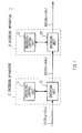
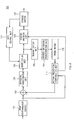
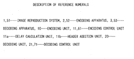
- reference numeral 1 shows an image reproduction system according to the first embodiment as a whole, which is constructed by connecting an encoding apparatus 2 with the JVT encoding system and a decoding apparatus 3 to each other with a prescribed transmission line.
- the encoding apparatus 2 includes an encoding unit 10 having the same construction as the encoding apparatus 100 described with reference to Fig. 8 and an encoding control unit 11 for controlling the encoding unit 10, and similarly to the case described with reference to Fig. 8, performs an encoding process on successive image information D1 through the encoding unit 10 controlled by the encoding control unit 11 to successively create encoded information D2 (D2a, D2b, ... or D2n) from unit image information (frame data or field data) D1a to D1n, and then outputs the encoded information D2, the successive image information D1 being supplied from the outside or being read from an internal recording medium (not shown) such as an HDD (Hard Disk Drive).
- an HDD Hard Disk Drive
- the decoding apparatus 3 includes a decoding unit 20 having the same construction as the decoding apparatus 120 described with reference to Fig. 9 and a decoding control unit 21 for controlling the decoding unit 20, and similarly to the case described with reference to Fig. 9, performs a decoding process on the encoded information D2 successively inputted through the transmission line, through the decoding unit 20 controlled by the decoding control unit 21 to successively create restored image information D3 (D3a, D3b, ... or D3n), and then successively outputs the restored image information D3 to a display unit (not shown), which results in continuous reproduction.
- a decoding unit 20 having the same construction as the decoding apparatus 120 described with reference to Fig. 9 and a decoding control unit 21 for controlling the decoding unit 20, and similarly to the case described with reference to Fig. 9, performs a decoding process on the encoded information D2 successively inputted through the transmission line, through the decoding unit 20 controlled by the decoding control unit 21 to successively create restored image information D3 (D3a, D3
- This encoding control unit 11 of the encoding apparatus 2 detects the GOP structure of the successive image information D1 inputted to the encoding unit 10 and conditions on an encoding process, such as an encoding order, (hereinafter, referred to as encoding conditions), based on previously stored programs, table information and so on with the JVT encoding system, to control the encoding unit 10 on the encoding conditions.
- encoding conditions an encoding order
- the encoding control unit 11 calculates output timing of the restored image information D3 which is a result of decoding the encoded information D2, anticipating that the encoded information D2 will be successively decoded on a decoding side (decoding apparatus 3), and performs an output timing notification process to notify the decoding apparatus 3 of this output timing before the restored image information D3 is created.
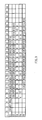
- the processing contents of the output timing notification processing by the encoding control unit 11 is divided functionally, they can be divided into a delay calculation unit 11a for calculating a period of time after a decoding process of the encoded information D2 is started until the decoded image information D3 created by the process is outputted (hereinafter, the period of time is referred to as decode delay), and a header addition unit 11b for adding a decode delay as the header of corresponding encoded information D2, as shown in Fig. 2. Processes by the delay calculation unit 11a and the header addition unit will be described by using an example shown in Fig. 3.
- a column “EI (Encoder Input)” shows picture types which are assigned to unit image information D1a to D1n to be inputted to the encoding unit 10, according to the GOP structure, that is, a picture-type order before the encoding process.
- a column “EO (Encoder Output)” shows the picture types of the encoded information D2a to D2n created by performing the encoding process on the unit image information D1a to D1n inputted to the encoding unit 10 in a prescribed encoding order, that is, a picture-type order after the encoding process.
- a column “Ed (Encoder Delay)" shows a period of time after the encoding process of unit image information D1a, D1b, ... or D1n is started until the encoded information D2 created by the process is outputted (hereinafter, this period of time is referred to as an encode delay) and the period of time is calculated based on the encoding conditions. Based on encode delays (in a column “Ed”), output timing of the encoded information D2a to D2n (in a column “EO”) are adjusted if necessary.
- the first unit image information D1a (100" in the column “EI") which is of an 1-picture type
- the delay calculation unit 11a calculates decode delays (in a column "Dd (Decoder Delay)") for the encoded information D2 based on the encode delays, and calculates the decode delays of the encoded information D2a to D2n so that a decode delay of encoded information D2 ("B13") having the longest encode delay (10 seconds) is the shortest (0 second).
- Dd Decoder Delay
- the delay calculation unit 11a subtracts the value of the encode delay corresponding to each piece of encoded information D2a to D2n from 10 [seconds] to thereby calculate the values of decode delays (values in the column "Dd") for the encoded information D2a to D2n.
- the delay calculation unit 11a creates decode delay information D10 from thus calculated decode delays and sends them to the header addition unit 11b.
- the header addition unit 11b adds, based on the decode delay information D10 supplied from the delay calculation unit 11a, a corresponding decode delay to the encoded information D2 by placing the delay in the header.
- the encoded information D2a (“100" in the column "EO") having such a decode delay added as the header is outputted when the encode delay is passed and is inputted into the decoding apparatus 3 through the transmission line.
- the transmission time through the transmission line between the encoding apparatus 2 and the decoding apparatus 3 is not considered, and therefore the input timing of encoded information D2 to the decoding apparatus 3 is taken as the same as the output timing (in the column "EO") of the encoded information D2 from the encoding apparatus 10.
- the other encoded information D2b to D2n similar to the encoded information D2a, they are converted into the restored image information D3b to D3n by the decoding unit 20, and these restored image information D3b to D3n are rearranged, if necessary, by the image rearrangement buffer 126 (Fig. 9) to have the same picture-type order before the encoding process (in a column "DO (Decoder Output)"), and are outputted after the output timing are adjusted based on corresponding encode delays, which results in continuous reproduction.
- DO Decoder Output
- the encode control unit 11 performs the output timing notification process as described above, to thereby make the decoding apparatus 3 recognize decode delays via headers, the decode delays calculated assuming that encoded information D2 will be decoded by the decoding apparatus 3.
- the encoding control unit 11 starts the procedure RT1 for the output timing notification process from step SP0 when predetermined operations to execute the encoding process are performed with an input unit (not shown), and finds out the longest encode delay (which corresponds to 10 [seconds] in the column "Ed” in Fig. 3) out of encode delays calculated on the encoding conditions at following step SP1.
- the encoding control unit 11 stores, for example, the encoded information D2a existing in the reverse encoding unit 106 (Fig. 8) of the encoding unit 10, in the storage buffer 107 (Fig. 8) at step SP2, and judges at step SP3 whether the storage has been done successfully, and if a negative result is obtained, the process returns back to step SP2 to re-store the encoded information D2a.
- the encoding control unit 11 subtracts the encode delay (which corresponds to 6 [seconds] in the column "Ed” in Fig. 3) for the encoded information D2a stored at step SP2 from the encode delay recognized at step SP1, to thereby calculate a decode delay (which corresponds to 4 [seconds] in the column "Dd") for the encoded information D2a, and adds the calculated decode delay to the encoded information D2a as a header at step SP4.
- the encoding control unit 11 judges at step SP5 whether all of the encoded information D2 have been taken in the storage buffer 107 (Fig. 8), and if a negative result is obtained, it returns back to step SP2 and repeats the above processes, and on the contrary, if an affirmative result is obtained, it moves on to step SP6 where the procedure RT1 for the output timing notification process is terminated.
- the encoding control unit 11 can execute the output timing notification process following the procedure RT1 for the output timing notification process.
- the encoding apparatus 2 calculates output timing (decode delay) for a result (restored image information D3) of decoding the encoded information D2, anticipating that the encoded information D2 obtained as a result of encoding with the JVT encoding system will be decoded on the decoding apparatus 3 side, and adds the calculated output timing as a header.
- this encoding apparatus 2 can make the decoding apparatus 3 recognize via headers decode delays which are obtained assuming that the encoded information D2 will be decoded by the decoding apparatus 3, before the decoding process, so that even the encoded information D2 have been encoded with the JVT encoding system which does not allow the decoding order to be naturally determined, the output continuousness of restored image information D3 can be kept.
- the encoding apparatus 2 calculates output timing (decode delays) for restored image information D3 so as to immediately output a result of decoding encoded information D2 ("B13" in Fig. 3) having the longest periods of time out of periods of time after the encoding process is started till encoded information D2 is outputted.
- the encoding apparatus 2 can calculate output timing (decode delays) for results (restored image information D3) of decoding encoded information D2 based on output timing (encode delays) from the decoding side for encoded information D2 which needs the longest time to be decoded on the decoding side, and as a result, the output timing from the decoding apparatus 3 can be adjusted (by offset) so as not to occur underflow.
- the aforementioned first embodiment has described the case where the JVT encoding system is applied.
- This invention is not limited to this and another kind of encoding system which can treat at least B-pictures as pictures to be prediction-encoded can be applied.
- a timing calculation means for assuming that a plurality of encoded information D2 created by performing the encoding process are sequentially decoded on a decoding side, calculating output timing for results of decoding the encoded information calculates decode delays for results of decoding the encoded information so that a result of decoding encoded information D2 having the longest encode delay out of the encode delays is immediately outputted.
- This invention is not limited to this and a period of time after a result of decoding encoded information is obtained until its output timing may be calculated instead of the decode delays, or a decode delay for a result of decoding encoded information may be calculated based on a calculation result on an assumed occupation rate of information stored in a buffer of the decoding side. If output timing can be calculated based on such a calculation result, such output timing can be calculated as to make the decoding side perform stable continuous reproduction.
- a timing notification means for notifying a decoding side of output timing before a result of decoding corresponding encoded information is obtained adds output timing (decode delay) to corresponding encoded information D2 as its header based on decode delay information D10 supplied from the delay calculation unit 11a.
- This invention is not limited to this and the decode delay information D10 can be directly outputted to the decoding side before an encoding process, without being added as a header.
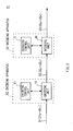
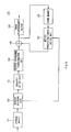
- reference numeral 51 shows an image reproduction system according to the second embodiment as a whole and the system is constructed by connecting an encoding apparatus 52 with the JVT encoding system and a decoding apparatus 53 to each other with a prescribed transmission line.
- the encoding apparatus 52 has an encoding unit 10 and an encoding control unit 61 for controlling the encoding unit 10, and the encoding control unit 61 does not perform the aforementioned output timing notification process but carries out the other processes performed in the aforementioned first embodiment.
- the encoding apparatus 52 performs an encoding process on successive image information D1 with the encoding unit 10 controlled by the encoding control unit 61, to thereby successively create encoded information D2 without a decode delay added as a header, and then successively outputs the encoded information D2.
- the decoding apparatus 53 has a decoding unit 20 and a decoding control unit 71 for controlling the decoding unit 20, and performs a decoding process on the encoded information D2 successively inputted through the transmission line, through the decoding unit 20 controlled by the decoding control unit 71, to thereby create restored image information D3, and then successively outputs the restored image information D3 to a display unit (not shown) for successive reproduction.
- the decoding control unit 71 of this decoding unit 53 temporarily stores successively inputted encoded information D2 in a storage buffer 121 (Fig. 9) of the decoding unit 20, detects conditions on decoding (hereinafter referred to as decoding conditions), such as a decoding order of the encoded information D2 and a start time of a decoding process, based on the headers of the encoded information D2, and thus can control the decoding unit 20 on the decoding conditions.
- decoding conditions such as a decoding order of the encoded information D2 and a start time of a decoding process
- the decoding control unit 71 watches a storage state of the restored image information D3 stored in an image rearrangement buffer 126 (Fig. 9) after the decoding process, and when detecting underflow as the storage state, carries out a re-output control process for re-outputting the restored image information D3 outputted just before the detection (underflow).
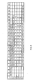
- This re-output control process will be described by using an example shown in Fig. 6.
- a column “EI” shows a picture-type order before an encoding process
- a column “EO” shows a picture-type order after the encoding process
- a column “DO” shows a picture-type order after decoding
- a column “Ed” shows encode delays
- a column “Dd” shows decode delays.
- a transmission time through the transmission line between the encoding apparatus 52 and the decoding apparatus 53 is not considered and an input time of encoded information D2 to the decoding apparatus 53 is taken to the same as an output time (in the column "EO") of the encoded information D2 from the encoding unit 10.
- a column “Sud (Start-up delay)" shows a period of time after each piece of encoded information D2 is inputted until a decoding process is started (hereinafter, this period of time is referred to as a start-up delay), and this start-up delay is calculated based on the encoding conditions by the encoding control unit 61 of the encoding apparatus 52 and is added as a header.
- the decoding control unit 71 When the decoding control unit 71 receives the first encoded information D2a ("100" in the column “EO”), it ignores the start-up delay for the encoded information D2a ("6" [seconds] in the column “Sud”) and performs control to immediately send the encoded information D2a to the reverse encoding unit 122 and start a decoding process ("0" [second] in the column “Dd”). As a result, the decoding control unit 71 can shorten a preparation time (driving time) for continuous reproduction.
- the decoding control unit 71 have encoded information D2b, D2c, ... successively inputted following the encoded information D2a ("P01”, “P02”, ... in the column “EO”), decoded according to the start-up delays, and manages the storage state of the restored image information D3b, D3c, ... ("P01", “P02”, ... in the column “DO") being stored in the image rearrangement buffer 126 (Fig. 9) after the decoding process.
- the decoding control unit 71 re-outputs the restored image information D3 outputted just before the failure ("P05” and "P10” in the column "DO"), to thereby periodically offset the other delay amounts to be adjusted.
- the decoding control unit 71 executes the re-output control process, so as to keep the output continuousness of the restored image information D3.
- the decoding control unit 71 starts the procedure RT2 for the re-output control process from step SP10, and waits for the first encoded information D2a to be inputted at next step SP11, and when receiving the encoded information D2a, moves on to step SP12.
- the decoding control unit 71 ignores a start-up delay for the encoded information D2a and immediately starts the decoding process at step SP12, and after outputting restored image information D3a obtained as a result of the decoding process at next step SP13, re-outputs the restored image information D3a at step SP14 to offset a part of a delay amount to be adjusted.
- the decoding control unit 71 starts decoding of following restored image information D2 (D2b, D2c, ... D2n) and outputs restored image information D3 (D3b, D3c, ... D3n) obtained by the process at step SP15, and at next step SP16 judges whether restored image information D3 to be stored in the image rearrangement buffer 126 (Fig. 9) has been failed, and then if a negative result is obtained, returns back to step SP15 and repeats the above processes.
- the decoding control unit 71 re-outputs the restored image information D3 ("P05" and "P10” in the column "DO") outputted at step SP15 to offset a part (or all) of the remaining delay amount to be adjusted and moves on to next step SP18.
- the decoding control unit 71 judges at step SP18 whether all of the delay amount to be adjusted is offset, and if a negative result is obtained, returns back to step SP15 and repeats the above processes. And if an affirmative result is obtained, on the contrary, the decoding control unit 71 moves on to step SP19 where this procedure RT2 for the re-output control process is terminated.
- the encoding control unit 11 can carries out the re-output control process following the procedure RT2 for the re-output control process.
- this decoding apparatus 53 temporarily stores the restored image information D3 successively created by performing the decoding process on the encoded information D2 which have been encoded with the JVT encoding system, in the image rearrangement buffer 126 (Fig. 9), and if restored image information D3 to be stored in the image rearrangement buffer 126 (Fig. 9) is failed, re-outputs the restored image information D3 outputted just before the failure.
- the decoding apparatus 53 can keep the output continuousness of the restored image information D3 even the encoded information D2 have been subjected to encoding with the JVT encoding system which does not allow a decoding order to be naturally determined.
- the decoding apparatus 53 ignores the decoding start time (start-up delay) set for the first encoded information D2 stored in the storage buffer 121 (Fig. 9) and immediately starts decoding of the encoded information D2a, and when restored image information D3 to be stored in the image rearrangement buffer 126 (Fig. 9) is failed, offsets a lag (delay amount to be adjusted) from the set decoding start time occurred due to the ignorance, by re-outputting the restored image information outputted just before the failure.
- the decoding apparatus 53 can shorten a preparation time (driving time) for continuous reproduction and can keep the output continuousness of restored image information while periodically dispersing a lag occurred due to the shortening (delay amount to be adjusted).
- the restored image information D3 sequentially created by performing the decoding process on the encoded information D2 which have been subjected to encoding with the JVT encoding system are temporarily stored in the image rearrangement buffer 126 (Fig. 9), and when restored image information D3 to be stored in the image rearrangement buffer 126 (Fig. 9) is failed, the restored image information D3 outputted just before the failure is re-outputted, so that even the encoded information D2 have been subjected to encoding with the JVT encoding system which does not allow a decoding order to be naturally determined, the output continuousness of the restored image information D3 can be kept, which results in the continuous reproduction.
- the aforementioned second embodiment has described the case where the JVT encoding system is applied.
- This invention is not limited to this and another kind of encoding system which can treat at least B-pictures as pictures to be prediction-encoded can be applied.
- the aforementioned second embodiment independently uses the storage buffer 121 and the rearrangement buffer 126 as storage means for temporarily storing encoded information and restored image information sequentially created by performing a decoding process on the encoded information.
- This invention is not limited to this and the storage buffer 121 and the rearrangement buffer 126 are used in common. In this case, the number of buffers and manner of storage can be changed according to necessity.
- the decoding control unit 71 serving as an output control means ignores a decoding start time (start-up delay) set for the first encoded information D2a being stored in the storage buffer 121 (Fig. 9) and immediately starts decoding of the encoded information D2a, and when restored image information D3 to be stored in the image rearrangement buffer 126 (Fig. 9) is failed, offsets a lag (a delay amount to be adjusted) from the set decoding start time occurred due to the ignorance, by re-outputting restored image information outputted just before the failure.
- start-up delay set for the first encoded information D2a being stored in the storage buffer 121 (Fig. 9) and immediately starts decoding of the encoded information D2a
- restored image information D3 to be stored in the image rearrangement buffer 126 (Fig. 9) is failed, offsets a lag (a delay amount to be adjusted) from the set decoding start time occurred due to the ignorance, by re-outputting restored image information outputted just before the failure.
- the restored image information D3 corresponding to the encoded information D2 having the different order may be re-outputted.
- a decode delay which becomes longer when a different order is generated can be filled by re-output, which results in more assured output continuousness of the restored image information D3.
- This invention can be used for a case of transmitting successive image information via a network medium such as satellite broadcasting, cable TV or the Internet, or a case of processing the successive image information on a storage medium such as an optical disc, magnetic disk or flash memory.
- a network medium such as satellite broadcasting, cable TV or the Internet
- a storage medium such as an optical disc, magnetic disk or flash memory.
Landscapes
- Engineering & Computer Science (AREA)
- Multimedia (AREA)
- Signal Processing (AREA)
- Computing Systems (AREA)
- Theoretical Computer Science (AREA)
- Compression Or Coding Systems Of Tv Signals (AREA)
Applications Claiming Priority (5)
| Application Number | Priority Date | Filing Date | Title |
|---|---|---|---|
| JP2002211829 | 2002-07-19 | ||
| JP2002211829 | 2002-07-19 | ||
| JP2003276326 | 2003-07-17 | ||
| JP2003276326A JP4806888B2 (ja) | 2002-07-19 | 2003-07-17 | 復号化装置及び復号化方法 |
| PCT/JP2003/009138 WO2004010707A1 (fr) | 2002-07-19 | 2003-07-18 | Dispositif de codage, procede de codage, dispositif de decodage et procede de decodage |
Publications (2)
| Publication Number | Publication Date |
|---|---|
| EP1536651A1 true EP1536651A1 (fr) | 2005-06-01 |
| EP1536651A4 EP1536651A4 (fr) | 2010-12-29 |
Family
ID=30772222
Family Applications (1)
| Application Number | Title | Priority Date | Filing Date |
|---|---|---|---|
| EP03765323A Withdrawn EP1536651A4 (fr) | 2002-07-19 | 2003-07-18 | Dispositif de codage, procede de codage, dispositif de decodage et procede de decodage |
Country Status (6)
| Country | Link |
|---|---|
| US (2) | US8259799B2 (fr) |
| EP (1) | EP1536651A4 (fr) |
| JP (1) | JP4806888B2 (fr) |
| KR (1) | KR100960821B1 (fr) |
| CN (1) | CN1669331A (fr) |
| WO (1) | WO2004010707A1 (fr) |
Families Citing this family (7)
| Publication number | Priority date | Publication date | Assignee | Title |
|---|---|---|---|---|
| US8369402B2 (en) | 2004-06-17 | 2013-02-05 | Canon Kabushiki Kaisha | Apparatus and method for prediction modes selection based on image formation |
| JP4247680B2 (ja) * | 2004-07-07 | 2009-04-02 | ソニー株式会社 | 符号化装置、符号化方法、符号化方法のプログラム及び符号化方法のプログラムを記録した記録媒体 |
| US8483289B2 (en) | 2008-04-17 | 2013-07-09 | Broadcom Corporation | Method and system for fast channel change |
| JP2006157481A (ja) | 2004-11-30 | 2006-06-15 | Canon Inc | 画像符号化装置及びその方法 |
| CN101888550A (zh) * | 2010-06-28 | 2010-11-17 | 中兴通讯股份有限公司 | 一种slice头信息中量化参数编码方法和装置 |
| CN103416060B (zh) * | 2011-03-11 | 2016-12-21 | 索尼公司 | 图像处理装置和方法 |
| US10817224B2 (en) | 2016-06-23 | 2020-10-27 | Qualcomm Incorporated | Preemptive decompression scheduling for a NAND storage device |
Family Cites Families (27)
| Publication number | Priority date | Publication date | Assignee | Title |
|---|---|---|---|---|
| WO1991002419A1 (fr) * | 1989-08-09 | 1991-02-21 | Alcatel N.V. | Systeme de remise en sequence pour n×ud de commutation |
| US5481543A (en) * | 1993-03-16 | 1996-01-02 | Sony Corporation | Rational input buffer arrangements for auxiliary information in video and audio signal processing systems |
| JPH0818953A (ja) * | 1994-07-01 | 1996-01-19 | Hitachi Ltd | 動画像復号表示装置 |
| JP3017646B2 (ja) * | 1994-11-25 | 2000-03-13 | 株式会社グラフィックス・コミュニケーション・ラボラトリーズ | フレームレート変換機能付き画像復号装置 |
| JP3644995B2 (ja) | 1995-01-25 | 2005-05-11 | 株式会社日立国際電気 | 符号化伝送方式におけるタイムスタンプ値演算方法 |
| JP3824678B2 (ja) * | 1995-05-09 | 2006-09-20 | 株式会社ルネサステクノロジ | 画像復号表示装置 |
| JP3301274B2 (ja) * | 1995-06-20 | 2002-07-15 | 株式会社日立製作所 | 符号化映像データの復号装置 |
| JP3810830B2 (ja) | 1995-07-20 | 2006-08-16 | 株式会社日立製作所 | 符号化映像信号の復号化処理方法及びそれを用いた復号化装置 |
| JP3556381B2 (ja) * | 1996-03-13 | 2004-08-18 | 株式会社東芝 | 情報多重化装置 |
| US6167083A (en) * | 1997-04-04 | 2000-12-26 | Avid Technology, Inc. | Computer system and process for capture editing and playback of motion video compressed using interframe and intraframe techniques |
| JPH1118083A (ja) * | 1997-06-25 | 1999-01-22 | Sony Corp | ディジタル信号符号化方法及び装置、信号記録媒体並びに信号伝送方法 |
| KR100750520B1 (ko) * | 1997-09-25 | 2007-08-21 | 소니 가부시끼 가이샤 | 부호화 스트림 생성 장치 및 방법, 데이터 전송 시스템 및 방법, 편집 시스템 및 방법 |
| JPH11122113A (ja) | 1997-10-09 | 1999-04-30 | Sony Corp | データ復号化装置及び方法 |
| JP3232052B2 (ja) | 1997-10-31 | 2001-11-26 | 松下電器産業株式会社 | 画像復号化方法 |
| US6963608B1 (en) * | 1998-10-02 | 2005-11-08 | General Instrument Corporation | Method and apparatus for providing rate control in a video encoder |
| US6285405B1 (en) * | 1998-10-14 | 2001-09-04 | Vtel Corporation | System and method for synchronizing data signals |
| JP2000228768A (ja) | 1999-02-05 | 2000-08-15 | Sony Corp | デジタル信号伝送装置および方法、並びに提供媒体 |
| JP2000333163A (ja) * | 1999-05-24 | 2000-11-30 | Sony Corp | 復号装置及び方法、符号化装置及び方法、画像処理システム、画像処理方法 |
| JP2000350183A (ja) | 1999-06-03 | 2000-12-15 | Canon Inc | 撮像装置遠隔制御システム |
| JP2001238110A (ja) | 2000-02-24 | 2001-08-31 | Sony Corp | 撮像装置および方法、並びに記録媒体 |
| JP2001251616A (ja) * | 2000-03-02 | 2001-09-14 | Media Glue Corp | 多重化音響・動画圧縮符号化信号変換方法、装置および変換プログラムを記録した媒体 |
| GB2362531A (en) | 2000-05-15 | 2001-11-21 | Nokia Mobile Phones Ltd | Indicating the temporal order of reference frames in a video sequence |
| JP2002091424A (ja) | 2000-09-20 | 2002-03-27 | Matsushita Electric Ind Co Ltd | 画像表示装置及び画像表示方法 |
| JP4208398B2 (ja) | 2000-10-05 | 2009-01-14 | 株式会社東芝 | 動画像復号再生装置、動画像復号再生方法及びマルチメディア情報受信装置 |
| US7706445B2 (en) * | 2001-05-31 | 2010-04-27 | Sanyo Electric Co., Ltd. | Image processing employing picture type conversion |
| JP3866628B2 (ja) | 2002-07-16 | 2007-01-10 | 日本電信電話株式会社 | 動画像符号化方法,動画像復号方法,画像符号化装置,画像復号装置,動画像符号化プログラム,動画像復号プログラムおよびそれらのプログラムの記録媒体 |
| JP3534742B1 (ja) | 2002-10-03 | 2004-06-07 | 株式会社エヌ・ティ・ティ・ドコモ | 動画像復号方法、動画像復号装置、及び動画像復号プログラム |
-
2003
- 2003-07-17 JP JP2003276326A patent/JP4806888B2/ja not_active Expired - Fee Related
- 2003-07-18 KR KR20057000542A patent/KR100960821B1/ko not_active Expired - Fee Related
- 2003-07-18 EP EP03765323A patent/EP1536651A4/fr not_active Withdrawn
- 2003-07-18 US US10/519,840 patent/US8259799B2/en not_active Expired - Fee Related
- 2003-07-18 CN CNA038170892A patent/CN1669331A/zh active Pending
- 2003-07-18 WO PCT/JP2003/009138 patent/WO2004010707A1/fr not_active Ceased
-
2011
- 2011-03-11 US US13/046,341 patent/US8228988B2/en not_active Expired - Fee Related
Also Published As
| Publication number | Publication date |
|---|---|
| US8228988B2 (en) | 2012-07-24 |
| KR20050028017A (ko) | 2005-03-21 |
| JP4806888B2 (ja) | 2011-11-02 |
| WO2004010707A1 (fr) | 2004-01-29 |
| JP2004056827A (ja) | 2004-02-19 |
| US20050238099A1 (en) | 2005-10-27 |
| US20110158318A1 (en) | 2011-06-30 |
| CN1669331A (zh) | 2005-09-14 |
| US8259799B2 (en) | 2012-09-04 |
| KR100960821B1 (ko) | 2010-06-07 |
| EP1536651A4 (fr) | 2010-12-29 |
Similar Documents
| Publication | Publication Date | Title |
|---|---|---|
| KR100950743B1 (ko) | 화상 정보 부호화 장치 및 방법, 및 화상 정보 복호 장치및 방법 | |
| EP1696677B1 (fr) | Dispositif de decodage d'image, procede de decodage d'image et programme de decodage d'image | |
| JP4676450B2 (ja) | デジタルビデオ符号化処理における可変精度ピクチャ間タイミング指定方法及び装置 | |
| US8228988B2 (en) | Encoding device, encoding method, decoding device, and decoding method | |
| US20020057739A1 (en) | Method and apparatus for encoding video | |
| JPH0537915A (ja) | 画像信号符号化方法と画像信号符号化装置 | |
| US20050111551A1 (en) | Data processing apparatus and method and encoding device of same | |
| US6271774B1 (en) | Picture data processor, picture data decoder and picture data encoder, and methods thereof | |
| JPH06225279A (ja) | 符号化方法、復号化方法、符号化装置及び復号化装置 | |
| JP3200199B2 (ja) | 動画像圧縮符号化方法 | |
| US20030016757A1 (en) | Signal processing apparatus and method | |
| JP4345024B2 (ja) | 画像符号化装置、画像符号化方法及び画像符号化プログラムを記録した記録媒体 | |
| JP5007759B2 (ja) | 符号化装置、符号化方法、復号化装置及び復号化方法 | |
| JPH07115649A (ja) | 映像信号符号化復号化装置 | |
| JPH06339111A (ja) | 圧縮動画像再生装置 | |
| JP2005080004A (ja) | 動画像符号化装置 | |
| JP4655791B2 (ja) | 符号化装置、符号化方法およびそのプログラム | |
| JP2002218470A (ja) | 画像符号化データのレート変換方法、及び画像符号化レート変換装置 | |
| JP3480980B2 (ja) | 画像信号伝送方法及び装置、並びに画像信号復号化方法及び装置 | |
| JP3481207B2 (ja) | 画像信号伝送方法及び装置、並びに画像信号復号化方法及び装置 | |
| JP2005176259A (ja) | データ処理装置およびその方法と符号化装置 |
Legal Events
| Date | Code | Title | Description |
|---|---|---|---|
| PUAI | Public reference made under article 153(3) epc to a published international application that has entered the european phase |
Free format text: ORIGINAL CODE: 0009012 |
|
| 17P | Request for examination filed |
Effective date: 20050119 |
|
| AK | Designated contracting states |
Kind code of ref document: A1 Designated state(s): AT BE BG CH CY CZ DE DK EE ES FI FR GB GR HU IE IT LI LU MC NL PT RO SE SI SK TR |
|
| RBV | Designated contracting states (corrected) |
Designated state(s): DE FR GB |
|
| A4 | Supplementary search report drawn up and despatched |
Effective date: 20101130 |
|
| 17Q | First examination report despatched |
Effective date: 20120322 |
|
| STAA | Information on the status of an ep patent application or granted ep patent |
Free format text: STATUS: THE APPLICATION IS DEEMED TO BE WITHDRAWN |
|
| 18D | Application deemed to be withdrawn |
Effective date: 20190201 |