EP1536997B1 - Procede pour remplacer le fluide sous pression d'un systeme de freinage electrohydraulique - Google Patents
Procede pour remplacer le fluide sous pression d'un systeme de freinage electrohydraulique Download PDFInfo
- Publication number
- EP1536997B1 EP1536997B1 EP03750411A EP03750411A EP1536997B1 EP 1536997 B1 EP1536997 B1 EP 1536997B1 EP 03750411 A EP03750411 A EP 03750411A EP 03750411 A EP03750411 A EP 03750411A EP 1536997 B1 EP1536997 B1 EP 1536997B1
- Authority
- EP
- European Patent Office
- Prior art keywords
- pressure fluid
- pressure
- brake
- wheel
- pressure medium
- Prior art date
- Legal status (The legal status is an assumption and is not a legal conclusion. Google has not performed a legal analysis and makes no representation as to the accuracy of the status listed.)
- Expired - Lifetime
Links
- 238000000034 method Methods 0.000 title claims description 22
- 239000012530 fluid Substances 0.000 claims abstract description 39
- 230000000740 bleeding effect Effects 0.000 abstract 1
- 238000010586 diagram Methods 0.000 description 9
- 238000002955 isolation Methods 0.000 description 5
- 230000010349 pulsation Effects 0.000 description 2
- 230000008439 repair process Effects 0.000 description 2
- 238000004088 simulation Methods 0.000 description 2
- 238000013022 venting Methods 0.000 description 2
- 230000000694 effects Effects 0.000 description 1
- 238000011010 flushing procedure Methods 0.000 description 1
- 239000003550 marker Substances 0.000 description 1
- 238000005086 pumping Methods 0.000 description 1
- 230000001105 regulatory effect Effects 0.000 description 1
- 238000009423 ventilation Methods 0.000 description 1
- XLYOFNOQVPJJNP-UHFFFAOYSA-N water Substances O XLYOFNOQVPJJNP-UHFFFAOYSA-N 0.000 description 1
Images

Classifications
-
- B—PERFORMING OPERATIONS; TRANSPORTING
- B60—VEHICLES IN GENERAL
- B60T—VEHICLE BRAKE CONTROL SYSTEMS OR PARTS THEREOF; BRAKE CONTROL SYSTEMS OR PARTS THEREOF, IN GENERAL; ARRANGEMENT OF BRAKING ELEMENTS ON VEHICLES IN GENERAL; PORTABLE DEVICES FOR PREVENTING UNWANTED MOVEMENT OF VEHICLES; VEHICLE MODIFICATIONS TO FACILITATE COOLING OF BRAKES
- B60T8/00—Arrangements for adjusting wheel-braking force to meet varying vehicular or ground-surface conditions, e.g. limiting or varying distribution of braking force
- B60T8/32—Arrangements for adjusting wheel-braking force to meet varying vehicular or ground-surface conditions, e.g. limiting or varying distribution of braking force responsive to a speed condition, e.g. acceleration or deceleration
- B60T8/34—Arrangements for adjusting wheel-braking force to meet varying vehicular or ground-surface conditions, e.g. limiting or varying distribution of braking force responsive to a speed condition, e.g. acceleration or deceleration having a fluid pressure regulator responsive to a speed condition
- B60T8/40—Arrangements for adjusting wheel-braking force to meet varying vehicular or ground-surface conditions, e.g. limiting or varying distribution of braking force responsive to a speed condition, e.g. acceleration or deceleration having a fluid pressure regulator responsive to a speed condition comprising an additional fluid circuit including fluid pressurising means for modifying the pressure of the braking fluid, e.g. including wheel driven pumps for detecting a speed condition, or pumps which are controlled by means independent of the braking system
- B60T8/4072—Systems in which a driver input signal is used as a control signal for the additional fluid circuit which is normally used for braking
- B60T8/4081—Systems with stroke simulating devices for driver input
-
- B—PERFORMING OPERATIONS; TRANSPORTING
- B60—VEHICLES IN GENERAL
- B60T—VEHICLE BRAKE CONTROL SYSTEMS OR PARTS THEREOF; BRAKE CONTROL SYSTEMS OR PARTS THEREOF, IN GENERAL; ARRANGEMENT OF BRAKING ELEMENTS ON VEHICLES IN GENERAL; PORTABLE DEVICES FOR PREVENTING UNWANTED MOVEMENT OF VEHICLES; VEHICLE MODIFICATIONS TO FACILITATE COOLING OF BRAKES
- B60T17/00—Component parts, details, or accessories of power brake systems not covered by groups B60T8/00, B60T13/00 or B60T15/00, or presenting other characteristic features
- B60T17/18—Safety devices; Monitoring
- B60T17/22—Devices for monitoring or checking brake systems; Signal devices
- B60T17/221—Procedure or apparatus for checking or keeping in a correct functioning condition of brake systems
- B60T17/222—Procedure or apparatus for checking or keeping in a correct functioning condition of brake systems by filling or bleeding of hydraulic systems
-
- B—PERFORMING OPERATIONS; TRANSPORTING
- B60—VEHICLES IN GENERAL
- B60T—VEHICLE BRAKE CONTROL SYSTEMS OR PARTS THEREOF; BRAKE CONTROL SYSTEMS OR PARTS THEREOF, IN GENERAL; ARRANGEMENT OF BRAKING ELEMENTS ON VEHICLES IN GENERAL; PORTABLE DEVICES FOR PREVENTING UNWANTED MOVEMENT OF VEHICLES; VEHICLE MODIFICATIONS TO FACILITATE COOLING OF BRAKES
- B60T8/00—Arrangements for adjusting wheel-braking force to meet varying vehicular or ground-surface conditions, e.g. limiting or varying distribution of braking force
- B60T8/32—Arrangements for adjusting wheel-braking force to meet varying vehicular or ground-surface conditions, e.g. limiting or varying distribution of braking force responsive to a speed condition, e.g. acceleration or deceleration
- B60T8/34—Arrangements for adjusting wheel-braking force to meet varying vehicular or ground-surface conditions, e.g. limiting or varying distribution of braking force responsive to a speed condition, e.g. acceleration or deceleration having a fluid pressure regulator responsive to a speed condition
Definitions
- the invention relates to a method for changing the pressure medium of an electro-hydraulic brake system, consisting of a pedal-operated master cylinder and a brake master cylinder pressure controlled brake circuit with a pump, the suction side is connected via a suction line to a pressure medium reservoir, and inlet and outlet valves for the at Brake circuit connected wheel brakes, wherein an outlet valve controls the connection of the associated wheel brake to the pressure fluid reservoir via a non-return return line, in which a conventional change of the pressure medium by multiple, manual operation of the brake pedal and switching on the pump and conveying pressure medium from the reservoir is provided.
- a method for venting and filling a slip-controlled dual-circuit brake system for motor vehicles is known.
- the ventilation of the wheel brakes is performed in two operating sections.
- the wheel brakes of the front axle and the rear axle are pre-ventilated by cyclically actuating the brake pressure transducer to subsequently perform the main venting and filling of the front and rear wheel brakes by actuating cycles of the brake pressure generator, the pressure modulation valves and commissioning of the pump in the second operating section.
- an electro-hydraulic brake system such a carried out change of the pressure medium is not sufficient to supply all areas of the brake system with fresh pressure medium.
- the invention is thus based on the problem of representing a method for an electro-hydraulic brake system, which makes it possible to perform a pressure medium change, in which all areas of the brake system are supplied with fresh pressure medium.
- the invention provides that a switching of the intake and exhaust valves and a separating valve is provided so that pressure fluid from a high-pressure accumulator either to the Radentllibraryeran somebodyn or enters the pressure medium reservoir, wherein the connection of the associated wheel brake to the high-pressure accumulator controlled by an inlet valve and the master cylinder is connected to the brake circuit via the isolation valve downstream of the intake valves.
- the change of pressure means for that part of the piping system can be done conventionally, i. H. fresh pressure fluid is replenished through the pressure fluid reservoir and pumped by the multiple, manual operation of the brake pedal from the master cylinder via the brake lines to the wheel brakes, where it is discharged at corresponding Radentllibraryeran somebodyn.
- the pump is turned on and the valves of the system controlled so that fresh pressure medium is pumped by the pump in these areas.
- the pump can also be controlled in a clocked manner in order to generate pressure pulsations with which air bubbles are released in the line system. The same effect is achieved when the exhaust valves are controlled in a clocked manner.
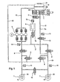
- FIG. 1 shows a typical electro-hydraulic brake system, which is constructed as follows:
- a master cylinder 1 in tandem has two brake circuits, namely a primary circuit (also called pressure Stan gen Vietnamese DK) and a secondary circuit SK, wherein the illustrated primary brake circuit 2 is connected to a 3 mulator Pedalsi.
- a pressure medium reservoir 4 is connected to the master cylinder 1.
- Motor-driven pumps 5 and a high pressure memory, z. B. a Metallfaltenbalg Cards 6, form a pressure supply system, which is supplied from the pressure fluid reservoir 4 with a pressure medium (brake fluid), to which the pump 5 is connected via a suction line 17 to the pressure medium reservoir 4.
- the wheel brakes 7 of the rear axle are each connected via a single A laßventil 8 to this Druckstoffschver- supply system.
- the intake and exhaust valves 8, 9 are normally closed.
- a pressure build-up in the wheel brakes 7 takes place by opening the respective inlet valve 8, a pressure reduction by opening the respective outlet valve 9.
- a controlled brake circuit 2 ' is formed, where-in the wheel brakes 7 available ge determined pressure from the master cylinder pressure is, which is hydraulically separated from the wheel brakes 7 ge at a controlled braking.
- an isolation valve 10 located in the line 2a, which opens downstream of the intake valve 8 in the leading to the wheel brakes 7 lines 2b, an isolation valve 10 which is closed in the control mode and only remains open when a fault in the controlled brake circuit 2 ', z. B. due to a failure of the pressure medium supply exists.
- the system is monitored and controlled by various pressure sensors.
- the individual wheel brakes 7 are associated with brake pressure sensors 11, the pressure medium supply system, a pump pressure sensor 12 and the main brake cylinder brake circuit each a simulation pressure sensor 13.
- the separating valve is closed.
- the pressure in the master cylinder serves as a control variable.
- the pressure of the main brake cylinder 1 is measured with the simulation pressure sensor 13 and given as a control variable to the control of the controlled brake circuit 2 '.
- the isolation valve 10 remains open.
- the wheel brakes 7 are thus connected in a conventional manner directly via lines 2 a and 2 b to the master cylinder 1.
- a compensation valve 14 ensures a pressure equalization between the wheel brakes of an axle.
- the brake system must be regularly maintained, in particular, the brake fluid must be changed. This can lead to errors. Thus, e.g. Interchanged connections or the brake system is not properly vented, resulting in air bubbles. In order to supply all areas of the brake system with fresh pressure medium and to check the brake system after any repairs, therefore, the following method is proposed:
- the wheel brakes 7 are, as indicated only schematically, optionally provided with valve-controlled Radentldiveran Wegn 20 through which the brake circuits pressure medium can be removed.
- fresh pressure medium is refilled manually via the filling nozzle 21 of the pressure medium reservoir 4 during the entire process.
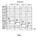
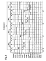
- the wheel ventilator connections VR, HR, VL and VR are opened one after the other (markings 101, 102, 103, 104), the brake pedal being manually actuated twenty times during an opening (marking 105 ).
- the conventional brake circuit consisting of the master cylinder 1, the isolation valve 2, the brake lines 2a, 2b and the wheel brakes 7, of fresh pressure medium flows through, as during the entire process on the filling nozzle 21 of the pressure medium reservoir 4 fresh pressure medium is manually refilled, as already mentioned above.
- the controlled brake circuit 2 'remains unaffected since both the intake valves 8 and the exhaust valves 9 remain closed.
- This process corresponds to a conventional change of the pressure medium, ie the change of the pressure medium of a conventional, non-regulated brake system.
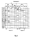
- the second switching sequence begins with a memory drain SE, in which the isolation valves 10 (marking 201) and the compensation valves 14 (marking 202) are closed.
- the following partial sequence 2.2 initially again provides for a storage discharge SE and a subsequent defined storage charge SF, in which the inlet valves 8 are closed, while the pump 5 delivers (marking 207). Thereafter, the inlet valve front left is opened and closed 40 times in short cycles of less than 0.1 second (mark 208), so that the memory 6 is emptied in a pulse-like manner and the pressure medium can flow out via the vent connection 20 in the front left.
- the memory is supplied with fresh pressure medium and also be solved by the pulse-like load of the system adhering bubbles, especially in the valve block.
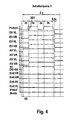
- process step 4 flushing of the return line 18 likewise takes place.
- the outlet valves are thereby removed 9 (marking 401 to 404) are switched clocked in succession, so that in turn pressure pulsations are generated and the return line 18 is rinsed intermittently. This should cause air bubbles to dissolve.
- the switching sequence 4 can be performed twice.
- the wheel ventilator connections 20 in the subsequences 5.1, 5.2, 5.3 and 5.4 are opened one after the other (marking 501 to 504).
- the intake valve 8 of the wheel brake with opened Radentldiveran gleich 20 is opened (marking 505)
- first the other three intake valves (triple) opened (marker 506), so that in the associated wheel brakes builds up a pressure shortly thereafter is reduced to about 2 bar by opening the associated outlet valves 9 (marking 507).
- the pressure in the wheel brakes can be monitored. This must correspond to the respective switching states.
Landscapes
- Engineering & Computer Science (AREA)
- Physics & Mathematics (AREA)
- Fluid Mechanics (AREA)
- Transportation (AREA)
- Mechanical Engineering (AREA)
- Valves And Accessory Devices For Braking Systems (AREA)
- Regulating Braking Force (AREA)
Abstract
Claims (6)
- Procédé à changer le fluide comprimé d'un système de freinage électro-hydraulique, composé d'un maître-cylindre de frein (1) commandé par pédale, et d'un circuit de frein commandé par la pression du maître-cylindre et comportant une pompe (5) le côté d'aspiration de laquelle par l'intermédiaire d'une conduite d'aspiration (17) est relié à un réservoir de fluide comprimé (4), et d'une soupape d'admission et d' une soupape de sortie (8, 9) pour les freins sur roue (7), une soupape de sortie (9) commandant la jonction des freins sur roue (7) affiliés au réservoir de fluide comprimé par l'intermédiaire d'une conduite à retour (18) non-comprimée où le fluide comprimé est changé de manière classique par l'intermédiaire d'une manuelle opération répétée de la pédale de frein, la pompe (5) est mise en oeuvre et du fluide comprimé est transporté du réservoir (4), caractérisé en ce qu' un réglage des soupapes d'admission et de sortie (8, 9) et d'une soupape séparatrice (10) est prévu pour transporter du fluide comprimé d'un réservoir à haute pression (6) soit aux raccords de purge-roue (20) soit au réservoir de fluide comprimé (4), la jonction du frein sur roue (7) affiliée au réservoir à haute pression (6) étant commandée par l'intermédiaire d'une soupape d'admission (8) et le cylindre maître de frein (1) étant relié par l'intermédiaire de la soupape séparatrice (10) au circuit de frein en aval des soupapes d'admission (8).
- Procédé selon la revendication 1, caractérisé en ce que du fluide comprimé frais est rempli par l'intermédiaire du réservoir de fluide comprimé pendant la mise en oeuvre des mesures de procédé.
- Procédé selon la revendication 1, caractérisé en ce que la pompe (5) pendant le transport du fluide comprimé dans le réservoir de fluide comprimé est actionnée périodiquement.
- Procédé selon la revendication 1, caractérisé en ce que les soupapes de sortie (9) pendant le transport du fluide comprimé dans le réservoir de fluide comprimé sont actionnées périodiquement.
- Procédé selon l'une des revendications précédentes, caractérisé en ce que le changement du fluide comprimé est exécuté par la pompe (5) dans l'ordre suivant :transport du fluide comprimé par l'intermédiaire de l'opération manuelle de la pédale de frein dans la direction des raccords (20) de purge-roues;circulation de la pompe du fluide comprimé également dans la direction des raccords (20) de purge-roues;chargement et déchargement du mémoire (6) de sorte que le fluide comprimé soit transporté dans la direction des raccords (20) de purge-roues;chargement et déchargement du mémoire (6) de sorte que le fluide comprimé soit transporté dans la direction du réservoir de fluide comprimé (4);circulation de fluide comprimé dans la direction des raccords (20) de purge-roues.
- Procédé selon l'une des revendications précédentes, caractérisé en ce que pendant le transport du fluide comprimé par l'intermédiaire des raccords (20) de purge-roues une force de pression est appliquée aux autres trois freins sur roue (7) en ouvrant les soupapes d'admission (8) affiliées, les compressions de roue étant mesurées et les compressions triples déterminées étant mises en corrélation aux soupapes d'admission (8).
Applications Claiming Priority (7)
| Application Number | Priority Date | Filing Date | Title |
|---|---|---|---|
| DE10237183 | 2002-08-14 | ||
| DE10237183 | 2002-08-14 | ||
| DE10309479A DE10309479A1 (de) | 2002-08-14 | 2003-03-05 | Verfahren zum Entlüften und Neubefüllen eines elektrohydraulischen Bremssystems |
| DE10309479 | 2003-03-05 | ||
| DE10316648A DE10316648A1 (de) | 2002-08-14 | 2003-04-11 | Verfahren zum Wechsel des Druckmittels eines elektrohydraulischen Bremssystems |
| DE10316648 | 2003-04-11 | ||
| PCT/EP2003/008986 WO2004016489A1 (fr) | 2002-08-14 | 2003-08-13 | Procede pour remplacer le fluide sous pression d'un systeme de freinage electrohydraulique |
Publications (2)
| Publication Number | Publication Date |
|---|---|
| EP1536997A1 EP1536997A1 (fr) | 2005-06-08 |
| EP1536997B1 true EP1536997B1 (fr) | 2007-01-17 |
Family
ID=31891709
Family Applications (1)
| Application Number | Title | Priority Date | Filing Date |
|---|---|---|---|
| EP03750411A Expired - Lifetime EP1536997B1 (fr) | 2002-08-14 | 2003-08-13 | Procede pour remplacer le fluide sous pression d'un systeme de freinage electrohydraulique |
Country Status (4)
| Country | Link |
|---|---|
| US (1) | US7461906B2 (fr) |
| EP (1) | EP1536997B1 (fr) |
| DE (1) | DE50306325D1 (fr) |
| WO (1) | WO2004016489A1 (fr) |
Families Citing this family (11)
| Publication number | Priority date | Publication date | Assignee | Title |
|---|---|---|---|---|
| DE10308737A1 (de) * | 2002-08-13 | 2004-02-26 | Continental Teves Ag & Co. Ohg | Verfahren zur Überprüfung der Entlüftungsgüte eines elektrohydraulischen Bremssystems |
| US20060192426A1 (en) * | 2002-08-14 | 2006-08-31 | Martin Baechle | Method for bleeding and refilling an electrohydraulic brake system |
| DE102004027508A1 (de) * | 2004-06-04 | 2005-12-22 | Robert Bosch Gmbh | Hydraulische Bremsanlage und Verfahren zur Beeinflussung einer hydraulischen Bremsanlage |
| WO2011091849A1 (fr) * | 2010-01-28 | 2011-08-04 | Continental Teves Ag & Co. Ohg | Appareil de commande électronique pour un système de freinage, approprié pour un système de réglage à distance |
| DE102010001943A1 (de) * | 2010-02-15 | 2011-08-18 | Robert Bosch GmbH, 70469 | Verfahren zum Betreiben eines hydraulischen Bremssystems eines Fahrzeugs und Steuervorrichtung für ein hydraulisches Bremssystems eines Fahrzeugs |
| DE102010002272A1 (de) * | 2010-02-24 | 2011-08-25 | Robert Bosch GmbH, 70469 | Bremssystem für ein Fahrzeug und Verfahren zum Betreiben eines Bremssystems eines Fahrzeugs |
| EP2674686B1 (fr) | 2011-02-07 | 2020-03-25 | Mitsubishi Electric Corporation | Dispositif de conditionnement d'air |
| DE102012221770B4 (de) * | 2012-05-14 | 2014-08-28 | Ford Global Technologies, Llc | Prüfverfahren für eine Bremsanlage |
| DE102017219598A1 (de) | 2017-01-11 | 2018-07-12 | Continental Teves Ag & Co. Ohg | Bremsanlage für Kraftfahrzeuge sowie Verfahren zum Betrieb einer Bremsanlage |
| EP3587203B1 (fr) * | 2018-06-29 | 2021-08-11 | Volvo Car Corporation | Procédé et système pour estimer la teneur en eau de liquide de frein dans un système de freinage |
| DE102019220355A1 (de) * | 2019-12-20 | 2021-06-24 | Robert Bosch Gesellschaft mit beschränkter Haftung | Hydraulische Fremdkraft-Fahrzeugbremsanlage und Verfahren zum Befüllen einer hydraulischen Fremdkraft-Fahrzeugbremsanlage |
Family Cites Families (11)
| Publication number | Priority date | Publication date | Assignee | Title |
|---|---|---|---|---|
| US4418803A (en) * | 1981-05-26 | 1983-12-06 | Clark Equipment Company | Method and means for bleeding hydraulic brakes |
| DE3324631A1 (de) * | 1983-07-08 | 1985-01-17 | Alfred Teves Gmbh, 6000 Frankfurt | Hydraulische bremsanlage |
| US4946230A (en) * | 1988-04-27 | 1990-08-07 | Mazda Motor Corporation | Method and an apparatus for charging an anti-lock brake system with brake liquid |
| DE3935353A1 (de) | 1989-10-24 | 1991-04-25 | Teves Gmbh Alfred | Verfahren zur entlueftung von hydraulikanlagen |
| DE4232130A1 (de) | 1992-09-25 | 1994-03-31 | Teves Gmbh Alfred | Verfahren und Schaltungsanordnung zur Regelung der Förderleistung einer Hydraulikpumpe |
| US5330259A (en) * | 1992-12-22 | 1994-07-19 | Alliedsignal Inc. | Electrohydraulic braking system with remote booster |
| DE19528859A1 (de) * | 1995-08-05 | 1997-02-06 | Teves Gmbh Alfred | Verfahren zur Entlüftung einer schlupfgeregelten Zweikreisbremsanlage für Kraftfahrzeuge |
| US5605384A (en) * | 1996-05-06 | 1997-02-25 | General Motors Corporation | Access valve evacuation and fill of inaccessible cavities |
| DE19700410A1 (de) | 1997-01-09 | 1998-07-16 | Teves Gmbh Alfred | Hydraulikaggregat |
| JP2004513841A (ja) * | 2000-11-23 | 2004-05-13 | コンティネンタル・テーベス・アクチエンゲゼルシヤフト・ウント・コンパニー・オッフェネ・ハンデルスゲゼルシヤフト | 電子制御可能なブレーキ操作装置の運転方法と電子制御可能なブレーキ操作装置 |
| DE10147180A1 (de) | 2000-11-23 | 2002-06-27 | Continental Teves Ag & Co Ohg | Verfahren zum Betreiben eines elektronisch regelbaren Bremsbetätigungssystems und elektronisch regelbares Bremsbetätigungssystem |
-
2003
- 2003-08-13 DE DE50306325T patent/DE50306325D1/de not_active Expired - Lifetime
- 2003-08-13 US US10/524,460 patent/US7461906B2/en not_active Expired - Fee Related
- 2003-08-13 EP EP03750411A patent/EP1536997B1/fr not_active Expired - Lifetime
- 2003-08-13 WO PCT/EP2003/008986 patent/WO2004016489A1/fr not_active Ceased
Also Published As
| Publication number | Publication date |
|---|---|
| WO2004016489A1 (fr) | 2004-02-26 |
| EP1536997A1 (fr) | 2005-06-08 |
| US20060152072A1 (en) | 2006-07-13 |
| DE50306325D1 (de) | 2007-03-08 |
| US7461906B2 (en) | 2008-12-09 |
Similar Documents
| Publication | Publication Date | Title |
|---|---|---|
| EP1451051B1 (fr) | Systeme de freinage electro-hydraulique comportant un simulateur de course de pedale de frein compose d'un cylindre de frein a accumulateur et d'un servopiston a couplage mecanique | |
| DE112009002349B4 (de) | Bremssteuerungsvorrichtung | |
| DE102012202645A1 (de) | Bremsanlage für Kraftfahrzeuge | |
| DE102012222897A1 (de) | Verfahren zum Betrieb einer Bremsanlage | |
| DE102005058799A1 (de) | Elektropneumatische Bremssteuerungseinrichtung | |
| DE102008000873B4 (de) | Verfahren zur Steuerung einer elektronisch schlupfregelbaren Fahrzeugbremsanlage | |
| EP4448351A1 (fr) | Système de freinage pour un véhicule automobile | |
| DE102009045714A1 (de) | Schlupfgeregelte hydraulische Fahrzeugbremsanlage | |
| EP3086986A1 (fr) | Système de freinage hydraulique et procédé pour faire fonctionner un système de freinage hydraulique | |
| EP1417118B1 (fr) | Procede pour degazer un systeme de freinage hydraulique de vehicule | |
| EP1530531A1 (fr) | Procede pour ventiler et remplir un systeme de freinage electrohydraulique | |
| EP1530532B1 (fr) | Procede de controle de la qualite de la purge d'air d'un systeme de freinage electro-hydraulique | |
| EP1536997A1 (fr) | Procede pour remplacer le fluide sous pression d'un systeme de freinage electrohydraulique | |
| EP4584139A1 (fr) | Procédé d'actionnement d'un système de freinage | |
| DE19939386B4 (de) | Verfahren zur Beurteilung hinsichtlich eines normalen Betriebs von Drucksensoren eines Bremssystems für Fahrzeuge | |
| DE102023208177B4 (de) | Rückfallebene mit weichem Pedal | |
| WO2003033323A1 (fr) | Systeme de freinage electrohydraulique destine a des vehicules automobiles | |
| WO2024132046A1 (fr) | Procédé pour faire fonctionner un système de frein lors de la détection d'une fuite, et dispositif de commande pour la mise en œuvre d'un tel procédé | |
| DE10316648A1 (de) | Verfahren zum Wechsel des Druckmittels eines elektrohydraulischen Bremssystems | |
| WO2018153567A1 (fr) | Système de freinage pour un véhicule automobile et procédé permettant de faire fonctionner un système de freinage pour un véhicule automobile | |
| EP2019766A1 (fr) | Système de freinage pour motocycle | |
| DE102023212502A1 (de) | Bremsanlage für Kraftfahrzeuge sowie Verfahren zu deren Betrieb | |
| DE102010062694A1 (de) | Hydraulische Bremsanlage und Verfahren zum Druckabgleich in einer hydraulischen Bremsanlage | |
| WO2018153527A1 (fr) | Système de freinage pour un véhicule automobile et procédé pour faire fonctionner un système de freinage | |
| DE102022210984A1 (de) | Verfahren zum Ermitteln einer Leckage eines Ventils eines Bremssystems und Steuervorrichtung zum Ausführen des Verfahrens |
Legal Events
| Date | Code | Title | Description |
|---|---|---|---|
| PUAI | Public reference made under article 153(3) epc to a published international application that has entered the european phase |
Free format text: ORIGINAL CODE: 0009012 |
|
| 17P | Request for examination filed |
Effective date: 20050314 |
|
| AK | Designated contracting states |
Kind code of ref document: A1 Designated state(s): AT BE CH CY DE DK ES FI FR GB GR IE IT LI LU MC NL PT SE TR |
|
| 17Q | First examination report despatched |
Effective date: 20050704 |
|
| RBV | Designated contracting states (corrected) |
Designated state(s): AT DE |
|
| GRAP | Despatch of communication of intention to grant a patent |
Free format text: ORIGINAL CODE: EPIDOSNIGR1 |
|
| GRAS | Grant fee paid |
Free format text: ORIGINAL CODE: EPIDOSNIGR3 |
|
| GRAA | (expected) grant |
Free format text: ORIGINAL CODE: 0009210 |
|
| AK | Designated contracting states |
Kind code of ref document: B1 Designated state(s): AT DE |
|
| REF | Corresponds to: |
Ref document number: 50306325 Country of ref document: DE Date of ref document: 20070308 Kind code of ref document: P |
|
| PLBE | No opposition filed within time limit |
Free format text: ORIGINAL CODE: 0009261 |
|
| STAA | Information on the status of an ep patent application or granted ep patent |
Free format text: STATUS: NO OPPOSITION FILED WITHIN TIME LIMIT |
|
| 26N | No opposition filed |
Effective date: 20071018 |
|
| PG25 | Lapsed in a contracting state [announced via postgrant information from national office to epo] |
Ref country code: AT Free format text: LAPSE BECAUSE OF NON-PAYMENT OF DUE FEES Effective date: 20070813 |
|
| PGFP | Annual fee paid to national office [announced via postgrant information from national office to epo] |
Ref country code: DE Payment date: 20180831 Year of fee payment: 16 |
|
| REG | Reference to a national code |
Ref country code: DE Ref legal event code: R119 Ref document number: 50306325 Country of ref document: DE |
|
| PG25 | Lapsed in a contracting state [announced via postgrant information from national office to epo] |
Ref country code: DE Free format text: LAPSE BECAUSE OF NON-PAYMENT OF DUE FEES Effective date: 20200303 |