EP1537314B1 - Procede pour calibrer le systeme de detection des cylindres d'un moteur a combustion interne, notamment d'une automobile, dont les cylindres fonctionnent de facon individuelle - Google Patents
Procede pour calibrer le systeme de detection des cylindres d'un moteur a combustion interne, notamment d'une automobile, dont les cylindres fonctionnent de facon individuelle Download PDFInfo
- Publication number
- EP1537314B1 EP1537314B1 EP03793578A EP03793578A EP1537314B1 EP 1537314 B1 EP1537314 B1 EP 1537314B1 EP 03793578 A EP03793578 A EP 03793578A EP 03793578 A EP03793578 A EP 03793578A EP 1537314 B1 EP1537314 B1 EP 1537314B1
- Authority
- EP
- European Patent Office
- Prior art keywords
- internal combustion
- combustion engine
- cylinders
- pressure
- indicated
- Prior art date
- Legal status (The legal status is an assumption and is not a legal conclusion. Google has not performed a legal analysis and makes no representation as to the accuracy of the status listed.)
- Expired - Lifetime
Links
- 238000002485 combustion reaction Methods 0.000 title claims description 48
- 238000000034 method Methods 0.000 title claims description 43
- 230000000694 effects Effects 0.000 claims description 3
- 238000012935 Averaging Methods 0.000 claims description 2
- 238000001914 filtration Methods 0.000 claims description 2
- 230000007257 malfunction Effects 0.000 claims 1
- 238000002347 injection Methods 0.000 description 7
- 239000007924 injection Substances 0.000 description 7
- 230000003321 amplification Effects 0.000 description 5
- 238000012937 correction Methods 0.000 description 5
- 230000001419 dependent effect Effects 0.000 description 5
- 239000000446 fuel Substances 0.000 description 5
- 238000003199 nucleic acid amplification method Methods 0.000 description 5
- 238000005259 measurement Methods 0.000 description 4
- 230000004913 activation Effects 0.000 description 2
- 238000013459 approach Methods 0.000 description 2
- 230000006835 compression Effects 0.000 description 2
- 238000007906 compression Methods 0.000 description 2
- 230000006978 adaptation Effects 0.000 description 1
- 230000002730 additional effect Effects 0.000 description 1
- 238000004364 calculation method Methods 0.000 description 1
- 230000008859 change Effects 0.000 description 1
- 230000007547 defect Effects 0.000 description 1
- 238000011156 evaluation Methods 0.000 description 1
- 239000012530 fluid Substances 0.000 description 1
- 230000007849 functional defect Effects 0.000 description 1
- 230000005484 gravity Effects 0.000 description 1
- 238000012886 linear function Methods 0.000 description 1
- 238000004519 manufacturing process Methods 0.000 description 1
- 238000005457 optimization Methods 0.000 description 1
- 230000008569 process Effects 0.000 description 1
- 238000012546 transfer Methods 0.000 description 1
Images

Classifications
-
- F—MECHANICAL ENGINEERING; LIGHTING; HEATING; WEAPONS; BLASTING
- F02—COMBUSTION ENGINES; HOT-GAS OR COMBUSTION-PRODUCT ENGINE PLANTS
- F02D—CONTROLLING COMBUSTION ENGINES
- F02D41/00—Electrical control of supply of combustible mixture or its constituents
- F02D41/008—Controlling each cylinder individually
- F02D41/0085—Balancing of cylinder outputs, e.g. speed, torque or air-fuel ratio
-
- F—MECHANICAL ENGINEERING; LIGHTING; HEATING; WEAPONS; BLASTING
- F02—COMBUSTION ENGINES; HOT-GAS OR COMBUSTION-PRODUCT ENGINE PLANTS
- F02D—CONTROLLING COMBUSTION ENGINES
- F02D35/00—Controlling engines, dependent on conditions exterior or interior to engines, not otherwise provided for
- F02D35/02—Controlling engines, dependent on conditions exterior or interior to engines, not otherwise provided for on interior conditions
- F02D35/023—Controlling engines, dependent on conditions exterior or interior to engines, not otherwise provided for on interior conditions by determining the cylinder pressure
-
- F—MECHANICAL ENGINEERING; LIGHTING; HEATING; WEAPONS; BLASTING
- F02—COMBUSTION ENGINES; HOT-GAS OR COMBUSTION-PRODUCT ENGINE PLANTS
- F02D—CONTROLLING COMBUSTION ENGINES
- F02D41/00—Electrical control of supply of combustible mixture or its constituents
- F02D41/24—Electrical control of supply of combustible mixture or its constituents characterised by the use of digital means
- F02D41/2406—Electrical control of supply of combustible mixture or its constituents characterised by the use of digital means using essentially read only memories
- F02D41/2425—Particular ways of programming the data
- F02D41/2429—Methods of calibrating or learning
- F02D41/2451—Methods of calibrating or learning characterised by what is learned or calibrated
- F02D41/2474—Characteristics of sensors
-
- G—PHYSICS
- G01—MEASURING; TESTING
- G01L—MEASURING FORCE, STRESS, TORQUE, WORK, MECHANICAL POWER, MECHANICAL EFFICIENCY, OR FLUID PRESSURE
- G01L27/00—Testing or calibrating of apparatus for measuring fluid pressure
- G01L27/007—Malfunction diagnosis, i.e. diagnosing a sensor defect
-
- G—PHYSICS
- G01—MEASURING; TESTING
- G01M—TESTING STATIC OR DYNAMIC BALANCE OF MACHINES OR STRUCTURES; TESTING OF STRUCTURES OR APPARATUS, NOT OTHERWISE PROVIDED FOR
- G01M15/00—Testing of engines
- G01M15/04—Testing internal-combustion engines
- G01M15/08—Testing internal-combustion engines by monitoring pressure in cylinders
-
- F—MECHANICAL ENGINEERING; LIGHTING; HEATING; WEAPONS; BLASTING
- F02—COMBUSTION ENGINES; HOT-GAS OR COMBUSTION-PRODUCT ENGINE PLANTS
- F02D—CONTROLLING COMBUSTION ENGINES
- F02D41/00—Electrical control of supply of combustible mixture or its constituents
- F02D41/24—Electrical control of supply of combustible mixture or its constituents characterised by the use of digital means
- F02D41/26—Electrical control of supply of combustible mixture or its constituents characterised by the use of digital means using computer, e.g. microprocessor
- F02D41/28—Interface circuits
- F02D2041/281—Interface circuits between sensors and control unit
-
- F—MECHANICAL ENGINEERING; LIGHTING; HEATING; WEAPONS; BLASTING
- F02—COMBUSTION ENGINES; HOT-GAS OR COMBUSTION-PRODUCT ENGINE PLANTS
- F02D—CONTROLLING COMBUSTION ENGINES
- F02D41/00—Electrical control of supply of combustible mixture or its constituents
- F02D41/22—Safety or indicating devices for abnormal conditions
- F02D41/222—Safety or indicating devices for abnormal conditions relating to the failure of sensors or parameter detection devices
-
- F—MECHANICAL ENGINEERING; LIGHTING; HEATING; WEAPONS; BLASTING
- F02—COMBUSTION ENGINES; HOT-GAS OR COMBUSTION-PRODUCT ENGINE PLANTS
- F02D—CONTROLLING COMBUSTION ENGINES
- F02D41/00—Electrical control of supply of combustible mixture or its constituents
- F02D41/24—Electrical control of supply of combustible mixture or its constituents characterised by the use of digital means
- F02D41/2406—Electrical control of supply of combustible mixture or its constituents characterised by the use of digital means using essentially read only memories
- F02D41/2425—Particular ways of programming the data
- F02D41/2429—Methods of calibrating or learning
- F02D41/2441—Methods of calibrating or learning characterised by the learning conditions
Definitions
- the invention relates generally to cylinder-individually operated internal combustion engines, in particular of motor vehicles, and more particularly to a method for calibrating sensors arranged in at least two cylinders of such an internal combustion engine for detecting a variable characterizing the combustion process in the respective cylinder.
- Cylinder-individually operated internal combustion engines frequently have a so-called quantity compensation control (MAR) or restraint control (LRR), which, for example, from the DE 199 45 618 A1 evident.
- MAR quantity compensation control
- LRR restraint control
- each cylinder of the internal combustion engine is assigned a controller.
- the background to this measure is that when quantity errors occur in the fuel metering an undesirable rotational nonuniformity occurs per se. If a cylinder meters an increased fuel quantity due to tolerances, the MAR causes a negative fuel quantity to be added to the driver's desired quantity for this cylinder. Conversely, a positive amount of fuel is added when a cylinder meters too little fuel.
- Equalization by means of MAR or LRR is now not efficient in all operating ranges of a diesel engine, since engine-type-dependent additional effects such as torsional vibrations on the crankshaft occur, which are also strongly dependent on engine speed. Therefore, methods have also been proposed for the cylinder-specific operation of an internal combustion engine, in which a direct evaluation of a signal directly related to the combustion, e.g. the cylinder pressure occurs. These methods allow a cylinder equalization even at higher speeds. With these methods, operating characteristics of the combustion process, for example the mean pressure indicated in the individual cylinders or the torque corresponding thereto or the center of gravity of the differential pressure between the individual cylinders, are calculated from the curve of the cylinder pressure. Thus, by controlling the indicated mean pressure, a more precise, cylinder-specific adjustment of the setpoint torques and thus a better equality of the cylinders in all operating ranges can be achieved.
- the cylinder pressures resulting during operation of the engine are detected by pressure sensors measured over time or over the crank angle and provided to a motor controller.
- a pressure sensor is, for example, from the DE 197 49 814 A1 out.
- methods are known with which from a high-resolution pressure signal during engine operation characteristics are determined, which in turn are then used for individual cylinder optimization of the engine process with respect to the target quantities consumption, emission and comfort.
- the parameters used are, for example, the pressure or pressure difference integrals, the indicated work or the indicated moment.
- the cited individual cylinder control usually takes place by means of actuators arranged in or on the cylinders, which are controlled by cylinder-specific manipulated variables.
- These manipulated variables are, for example, the activation periods and / or activation commensurate with an injection.
- the cylinder-pressure-based methods have the disadvantage that the measured values supplied by the pressure sensors are frequently subject to errors due to manufacturing and / or operational tolerances. If these measurement errors are not corrected, they will falsify the calculated cylinder pressure values and cause them due to the above Regulation as a result of detuning the individual cylinders with each other.
- the mentioned measurement errors are expressed in different sensor parameters, which are incorporated in sensor characteristics preferably both as error-prone offset and as an error-prone gain factor.
- sensor parameters which are incorporated in sensor characteristics preferably both as error-prone offset and as an error-prone gain factor.
- error-prone offset preferably both as error-prone offset and as an error-prone gain factor.
- the individual gain factors also play a superordinate role for the entire operation of an internal combustion engine, as they are incorporated directly in the calculation of many other cylinder pressure characteristics.
- the present invention is therefore based on the object of providing an initially mentioned method for calibrating sensors arranged in at least two cylinders of a cylinder-specific internal combustion engine for detecting a variable characterizing the combustion process in the respective cylinder, which enables a balancing of the at least two sensors with high precision.
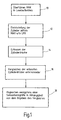
- the method according to the invention provides, in a first step, first of all to start at least one operating point of the internal combustion engine for carrying out said sensor calibration, in which an equalization of the cylinders in the o.g. Meaning with the above-mentioned quantity equalization methods such as.
- the MAR or the LRR with relatively high precision is possible.
- an equalization of the cylinders is then carried out by means of at least one of the set equalization methods.
- such operating points of the internal combustion engine can be selected, in which only slight disturbing side effects such as the already mentioned torsional vibrations of the crankshaft or an unequal combustion chamber / cylinder filling due to air mass vibrations are to be expected.
- a preferred such operating point is idle operation.
- the first step according to the invention is based on the finding that it can be assumed that equalization of the cylinders by means of a specified quantity equalization method means that all cylinders receive the same injection quantity and therefore supply the same torque or the same mean pressure.
- a second step the equality attained in the first step is utilized in order to match at least one of the mentioned sensor parameters of at least two pressure sensors.
- the sensors concerned here are preferably pressure sensors for detecting the internal cylinder pressure (mean pressure) occurring during combustion and thus indirectly the torque indicated by the combustion.
- the pressure profiles in the cylinders and the calculated operating parameters of the internal combustion engine are adapted to one another by means of the method according to the invention by the correction of the amplification factor and / or the offset of individual sensors.
- the method does not allow absolute calibration of the sensors, but a relative balance of the sensors with each other, whereby the cylinder-specific operation of the internal combustion engine is improved overall.
- the cylinder pressure profiles recorded in step 14 are compared 16 and with the result of this comparison, the individual Sennsorkennieren matched 18.
- other operating characteristics of the BKM can be used to adjust the sensor characteristics / lines.
- the adjustment can also be done by equating said calculated pmi values.
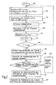
- the adjustment is technically simplifying in only a single operating point of the BKM, whereas in the in the described embodiment Fig. 2 illustrated embodiment, at least two operating points must be approached. The latter variant, however, allows a higher calibration quality.
- the illustrated embodiment may be used to reduce the influence of stroke-to-hub scattering in the cylinders of the BKM
- a filtering eg averaging over several operating cycles of the BKM be provided.
- Fig. 2 shows a second embodiment is shown, in which the sensor characteristics in several operating points of the BKM, ie in the present case at several loads at a constant speed, are adjusted.
- the sensor characteristics in several operating points of the BKM ie in the present case at several loads at a constant speed
- different friction moments or friction mean pressures pmR of the individual cylinders can be taken into account, which are due, for example, to different compression ratios in the individual cylinders.
- step 102 the BKM is transferred to an nth operating state, ie, in the present case, first to a first operating state.
- This first operating state is characterized by a load dependent on the injection quantity me at this operating point (me1) and a speed z assumed to be constant below.
- this first operating point of the BKM in step 104 equalization of the cylinders with each other by means of MAR / LRR, as based on the Fig. 1 described.
- the pressures present in the cylinders are detected 106 by means of the pressure sensors and the moments or mean pressures pmi indicated in the cylinders are calculated 108 from the detected pressure values.
- step 120 the gradients of these compensation lines are compared with one another and deviations between them are calculated in each case. If at least one of these deviations is greater than a threshold value to be determined empirically, an error message 122 is output in the present exemplary embodiment with regard to the function of the sensor system and / or the BKM itself. Step 122 is only optional.
- step 124 the gain factors of the individual pressure sensors are aligned with each other by adjusting the slopes of the compensation line.
- an adjustment of the frictional torques or friction mean pressures of the cylinders with one another is also automatically carried out 126 by means of the offset of the compensation straight line mentioned.
- a plausibility check of the ascertained sensor parameters, in particular of the ascertained amplification factors is additionally carried out. This additionally allows similar to step 122 in FIG Fig. 2 to detect possible functional defects on one or more of the pressure sensors or even defects on the BKM itself, but with one opposite Fig. 2 higher quality.
- the shows Fig. 3 after a cylinder equalization by means of MAR and LRR typically resulting sensor characteristics.
- the indicated moment or average pressure pmi calculated from the pressure values recorded in each cylinder is plotted against the injection quantity me measured in three different operating points of the BKM.
- Equalization lines have already been adapted to the measurement points using the method of least squares. The slope of this straight line results directly in the amplification factor of the respective pressure sensors.
- one of the three characteristic curves deviates visibly in their gradient from the other characteristic curves.
- a calibration according to the above method leads to a significantly improved calibration of the sensors with one another.
- the basic concepts of the invention are applicable not only to BKMs with cylindrically shaped combustion chambers, but with BKMs of any kind having at least two combustion chambers, such as Wankel engines. Furthermore, it is understood here that the invention not only in the above-described pressure sensors, but grds. in all the cylinder-individual operation of the BKM, i. for detecting a the combustion process in the cylinders directly or indirectly characterizing size suitable sensors such as. Injection quantity sensors or the like., Can be used.
Landscapes
- Engineering & Computer Science (AREA)
- Chemical & Material Sciences (AREA)
- Combustion & Propulsion (AREA)
- Mechanical Engineering (AREA)
- General Engineering & Computer Science (AREA)
- Analytical Chemistry (AREA)
- Physics & Mathematics (AREA)
- General Physics & Mathematics (AREA)
- Health & Medical Sciences (AREA)
- Biomedical Technology (AREA)
- Combined Controls Of Internal Combustion Engines (AREA)
- Electrical Control Of Air Or Fuel Supplied To Internal-Combustion Engine (AREA)
Claims (16)
- Procédé d'étalonnage d'au moins deux détecteurs servant à saisir une grandeur qui caractérise le processus de combustion dans un moteur à combustion interne de véhicule automobile qui présente au moins deux cylindres utilisés indépendamment,
le moteur à combustion interne étant amené (10) à au moins un point de fonctionnement auquel une égalisation du fonctionnement des deux ou plusieurs cylindres peut être réalisée au moyen d'au moins un procédé d'égalisation de quantité à haute précision, caractérisé en ce que
le ou les points de fonctionnement du moteur à combustion interne correspondent au régime de ralenti,
en ce qu'au ralenti, une égalisation des deux ou plusieurs cylindres est réalisée (12) au moyen du ou des procédés d'égalisation de quantité et
en ce que lorsque les deux ou plusieurs cylindres ont été égalisés, au moins une grandeur caractéristique des deux ou plusieurs détecteurs est égalisée (18), le ou les points de fonctionnement constituant le régime de ralenti. - Procédé selon la revendication 1, caractérisé en ce que la grandeur qui caractérise le processus de combustion dans chaque cylindre est représentée par la pression.
- Procédé selon les revendications 1 ou 2, caractérisé en ce que la grandeur caractéristique du détecteur qui est égalisée est le décalage et/ou un facteur d'amplification d'une ligne caractéristique du détecteur.
- Procédé selon l'une des revendications précédentes, caractérisé en ce que pour égaliser la ou les grandeurs caractéristiques du détecteur, on sélectionne des points de fonctionnement du moteur à combustion interne auxquels on peut s'attendre à ce que le fonctionnement du moteur à combustion interne entraîne peu d'effets perturbateurs.
- Procédé selon l'une des revendications précédentes, caractérisé en ce qu'à partir des grandeurs saisies par les deux ou plusieurs détecteurs, le couple d'indicateur dans le cylindre concerné ou la pression moyenne d'indicateur dans le cylindre concerné sont calculés, une différence entre les couples d'indicateur ou les pressions moyennes d'indicateur dans les deux ou plusieurs cylindres permettant de conclure que la grandeur caractéristique ou la ligne caractéristique du détecteur sont entachées d'erreurs.
- Procédé selon la revendication 5, caractérisé en ce que l'égalisation de la ou des grandeurs caractéristiques de détecteur s'effectue en égalisant dans les deux ou plusieurs détecteurs les couples d'indicateur ou les pressions moyennes d'indicateur calculés.
- Procédé selon la revendication 5, caractérisé en ce que l'égalisation de la ou des grandeurs caractéristiques de détecteur s'effectue (16) au moyen de la ou des grandeurs caractéristiques de fonctionnement.
- Procédé selon les revendications 6 ou 7, caractérisé en ce que l'égalisation est réalisée en un seul point de fonctionnement du moteur à combustion interne.
- Procédé selon la revendication 8, caractérisé en ce qu'un filtrage et en particulier la formation de la moyenne sont exécutés sur au moins deux cycles de fonctionnement du moteur à combustion interne.
- Procédé selon l'une des revendications précédentes, caractérisé en ce que l'égalisation est réalisée en au moins deux points de fonctionnement du moteur à combustion interne.
- Procédé selon la revendication 10, caractérisé en ce que l'égalisation des deux ou plusieurs grandeurs caractéristiques de détecteur s'effectue en au moins deux points de charge à des régimes de rotation constants du moteur à combustion interne.
- Procédé selon la revendication 10 ainsi que selon la revendication 5, caractérisé en ce que le couple d'indicateur ou la pression moyenne d'indicateur sont formés de la somme du couple effectif ou de la pression moyenne effective et du couple de frottement ou de la pression moyenne de frottement, le couple de frottement ou la pression moyenne de frottement des deux ou plusieurs cylindres étant supposés constants en première approximation, le facteur d'amplification respectif étant formé de la pente d'une droite de compensation (ligne caractéristique) passant par les valeurs des couples d'indicateur ou des pressions moyennes d'indicateur calculés au moyen de différentes quantités d'apport de carburant et le décalage par le couple de frottement ou la pression moyenne de frottement.
- Procédé selon la revendication 12, caractérisé en ce qu'un écart entre les droites de compensation (lignes caractéristiques) déterminées dans les deux ou plusieurs cylindres permet de conclure à la présence d'un fonctionnement défectueux du détecteur concerné et/ou du moteur à combustion interne concerné.
- Procédé selon l'une des revendications 1 à 11, caractérisé en ce que le couple d'indicateur ou la pression moyenne d'indicateur sont calculés à partir d'un polynôme formé par le couple effectif ou la pression moyenne effective et un couple de frottement ou une pression moyenne de frottement, le facteur d'amplification étant formé en lissant par calcul les courbes du couple d'indicateur ou de la pression moyenne d'indicateur calculées sur différentes quantités d'apport de carburant.
- Procédé selon la revendication 14, caractérisé en ce qu'il est basé sur un couple de frottement qui varie en fonction de la charge du moteur à combustion interne ou une pression moyenne de frottement qui varie en fonction de la charge du moteur à combustion interne.
- Procédé selon l'une des revendications précédentes, caractérisé en ce qu'une plausibilisation des grandeurs caractéristiques de détecteur saisies dans les deux ou plusieurs cylindre est réalisée.
Applications Claiming Priority (3)
| Application Number | Priority Date | Filing Date | Title |
|---|---|---|---|
| DE10240492 | 2002-09-03 | ||
| DE10240492A DE10240492A1 (de) | 2002-09-03 | 2002-09-03 | Verfahren zur Kalibrierung der Zylindersensorik einer zylinderindividuell betriebenen Brennkraftmaschine insbesondere eines Kraftfahrzeugs |
| PCT/DE2003/001713 WO2004022951A1 (fr) | 2002-09-03 | 2003-05-26 | Procede pour calibrer le systeme de detection des cylindres d'un moteur a combustion interne, notamment d'une automobile, dont les cylindres fonctionnent de façon individuelle |
Publications (2)
| Publication Number | Publication Date |
|---|---|
| EP1537314A1 EP1537314A1 (fr) | 2005-06-08 |
| EP1537314B1 true EP1537314B1 (fr) | 2013-03-27 |
Family
ID=31502281
Family Applications (1)
| Application Number | Title | Priority Date | Filing Date |
|---|---|---|---|
| EP03793578A Expired - Lifetime EP1537314B1 (fr) | 2002-09-03 | 2003-05-26 | Procede pour calibrer le systeme de detection des cylindres d'un moteur a combustion interne, notamment d'une automobile, dont les cylindres fonctionnent de facon individuelle |
Country Status (6)
| Country | Link |
|---|---|
| US (1) | US7260470B2 (fr) |
| EP (1) | EP1537314B1 (fr) |
| JP (1) | JP4369368B2 (fr) |
| CN (1) | CN100371574C (fr) |
| DE (1) | DE10240492A1 (fr) |
| WO (1) | WO2004022951A1 (fr) |
Families Citing this family (17)
| Publication number | Priority date | Publication date | Assignee | Title |
|---|---|---|---|---|
| EP1593825B1 (fr) * | 2004-05-05 | 2007-09-26 | Ford Global Technologies, LLC, A subsidary of Ford Motor Company | Système pour équilibrer des cylindres dans un moteur à combustion interne avec un capteur par cylindre |
| DE102005039757A1 (de) * | 2005-08-23 | 2007-03-01 | Robert Bosch Gmbh | Verfahren zum Betreiben einer Brennkraftmaschine |
| DE102005058820B4 (de) | 2005-12-09 | 2016-11-17 | Daimler Ag | Verfahren zur Regelung einer Brennkraftmaschine, insbesondere einer selbstzündenden Brennkraftmaschine |
| DE102006006381A1 (de) * | 2006-02-11 | 2007-08-16 | Deutz Ag | Einstellen des Kraftstoff-Luft-Verhältnisses bei Otto-Motoren |
| DE102006024956B4 (de) | 2006-05-29 | 2009-04-09 | Continental Automotive Gmbh | Verfahren und Vorrichtung zum Betreiben einer Brennkraftmaschine |
| JP4552898B2 (ja) * | 2006-05-30 | 2010-09-29 | 株式会社デンソー | 筒内圧センサの異常判定装置 |
| DE102006026876A1 (de) * | 2006-06-09 | 2007-12-13 | Robert Bosch Gmbh | Verfahren und Vorrichtung zur Steuerung der Kraftstoffzumessung in wenigstens einen Brennraum einer Brennkraftmaschine |
| FR2922267B1 (fr) * | 2007-10-11 | 2012-09-21 | Siemens Vdo Automotive | Detection et correction d'une derive d'injecteur |
| DE102009000134B4 (de) * | 2009-01-09 | 2019-12-05 | Robert Bosch Gmbh | Vorrichtung und Verfahren zur Zylindergleichstellung einer Brennkraftmaschine, Computerprogramm, Computerprogrammprodukt |
| EP2375038B1 (fr) * | 2010-04-08 | 2015-03-04 | Delphi International Operations Luxembourg S.à r.l. | Dispositif et procédé de diagnostic utilisant un capteur de pression dans un cylindre pour moteur à combustion interne |
| US9115655B2 (en) * | 2011-04-26 | 2015-08-25 | Allen B. Rayl | Cylinder pressure parameter correction systems and methods |
| US8600644B2 (en) * | 2011-05-23 | 2013-12-03 | GM Global Technology Operations LLC | Cylinder pressure sensor compensation systems and methods |
| WO2015027048A1 (fr) * | 2013-08-21 | 2015-02-26 | Advanced Sensor Design Technologies, LLC | Étalonnage d'un dispositif |
| US9890728B2 (en) * | 2015-08-21 | 2018-02-13 | Ford Global Technologies, Llc | Engine operating system and method |
| EP3320200B1 (fr) * | 2015-09-11 | 2020-05-13 | Wärtsilä Finland Oy | Procédé, et système de commande associé, pour déterminer un décalage par rapport à une mesure de l'angle de vilebrequin |
| CN111238725A (zh) * | 2020-02-18 | 2020-06-05 | 中南大学 | 电空制动系统压力传感器的故障诊断方法、装置及系统 |
| CN115701849B (zh) * | 2022-10-16 | 2025-12-02 | 中航天水飞机工业有限责任公司 | 机载燃油耗量表试验器及试验方法 |
Family Cites Families (12)
| Publication number | Priority date | Publication date | Assignee | Title |
|---|---|---|---|---|
| JPS59206648A (ja) * | 1983-01-26 | 1984-11-22 | Nissan Motor Co Ltd | 内燃機関の燃焼室内圧力を検出するセンサの較正方法 |
| JPS62192627A (ja) * | 1986-02-19 | 1987-08-24 | Honda Motor Co Ltd | 内燃機関の気筒内圧力の補正方法 |
| JP2592075B2 (ja) * | 1987-10-19 | 1997-03-19 | 日産自動車株式会社 | 可変圧縮比型内燃機関の制御装置 |
| JPH0364653A (ja) * | 1989-07-31 | 1991-03-20 | Japan Electron Control Syst Co Ltd | 内燃機関の筒内圧力検出装置 |
| DE3929746A1 (de) * | 1989-09-07 | 1991-03-14 | Bosch Gmbh Robert | Verfahren und einrichtung zum steuern und regeln einer selbstzuendenden brennkraftmaschine |
| JP2893233B2 (ja) * | 1993-12-09 | 1999-05-17 | 株式会社ユニシアジェックス | 筒内圧センサの診断装置 |
| JP3048531B2 (ja) * | 1996-12-12 | 2000-06-05 | 株式会社ゼクセル | 燃料噴射装置におけるセンサ故障診断方法及び燃料噴射装置におけるセンサ故障診断装置 |
| DE19749814B4 (de) | 1997-11-11 | 2009-01-22 | Robert Bosch Gmbh | Verfahren zur Bestimmung eines Brennraumdruckverlaufes |
| DE19927846C2 (de) * | 1999-06-18 | 2001-09-13 | Mtu Friedrichshafen Gmbh | Verfahren zur Überwachung einer Brennkraftmaschine |
| DE19945618B4 (de) | 1999-09-23 | 2017-06-08 | Robert Bosch Gmbh | Verfahren und Vorrichtung zur Steuerung eines Kraftstoffzumeßsystems einer Brennkraftmaschine |
| US6549843B1 (en) * | 2000-11-13 | 2003-04-15 | Bombardier Motor Corporation Of America | Diagnostic system and method to temporarily adjust fuel quantity delivered to a fuel injected engine |
| DE10159017A1 (de) | 2001-12-01 | 2003-06-18 | Bosch Gmbh Robert | Verfahren und Vorrichtung zur Steuerung einer Brennkraftmaschine |
-
2002
- 2002-09-03 DE DE10240492A patent/DE10240492A1/de not_active Withdrawn
-
2003
- 2003-05-26 WO PCT/DE2003/001713 patent/WO2004022951A1/fr not_active Ceased
- 2003-05-26 JP JP2004533190A patent/JP4369368B2/ja not_active Expired - Fee Related
- 2003-05-26 EP EP03793578A patent/EP1537314B1/fr not_active Expired - Lifetime
- 2003-05-26 US US10/525,179 patent/US7260470B2/en not_active Expired - Fee Related
- 2003-05-26 CN CNB03803512XA patent/CN100371574C/zh not_active Expired - Fee Related
Also Published As
| Publication number | Publication date |
|---|---|
| WO2004022951A1 (fr) | 2004-03-18 |
| CN1630772A (zh) | 2005-06-22 |
| JP4369368B2 (ja) | 2009-11-18 |
| US7260470B2 (en) | 2007-08-21 |
| US20060241852A1 (en) | 2006-10-26 |
| DE10240492A1 (de) | 2004-03-11 |
| EP1537314A1 (fr) | 2005-06-08 |
| CN100371574C (zh) | 2008-02-27 |
| JP2005537429A (ja) | 2005-12-08 |
Similar Documents
| Publication | Publication Date | Title |
|---|---|---|
| EP1537314B1 (fr) | Procede pour calibrer le systeme de detection des cylindres d'un moteur a combustion interne, notamment d'une automobile, dont les cylindres fonctionnent de facon individuelle | |
| DE19945618B4 (de) | Verfahren und Vorrichtung zur Steuerung eines Kraftstoffzumeßsystems einer Brennkraftmaschine | |
| DE102006026390B4 (de) | Elektronische Steuereinrichtung zur Steuerung der Brennkraftmaschine in einem Kraftfahrzeug | |
| DE69318012T2 (de) | Luft/kraftstoff-verhältnissteuerung | |
| DE102008054690B4 (de) | Verfahren und Vorrichtung zur Kalibrierung von Teileinspritzungen in einer Brennkraftmaschine, insbesondere eines Kraftfahrzeugs | |
| DE4208002B4 (de) | System zur Steuerung einer Brennkraftmaschine | |
| DE2650246A1 (de) | Steuereinrichtung fuer eine kraftstoffeinspritzpumpe eines dieselmotors | |
| DE10343759B4 (de) | Verfahren und Vorrichtung zur Bestimmung der Abweichung der tatsächlichen Einspritzmenge von einer berechneten Referenzeinspritzmenge eines Kraftstoffeinspritzsystems | |
| DE102004046083B4 (de) | Verfahren und Vorrichtung zur Steuerung einer Brennkraftmaschine | |
| DE3011595A1 (de) | Korrektureinrichtung fuer ein kraftstoffmesssystem bei einer brennkraftmaschine | |
| DE60022918T2 (de) | Steuerungsverfahren für eine selbstzündende Brennkraftmaschine | |
| DE10039785B4 (de) | Verfahren und Vorrichtung zum Betreiben einer Brennkraftmaschine | |
| WO2008034496A1 (fr) | Procédé de diagnostic d'un système d'approvisionnement en carburant | |
| EP4010677B1 (fr) | Banc d'essai et procédé permettant d'effectuer un essai sur un banc d'essai | |
| DE102008002482B4 (de) | Verfahren und Vorrichtung zur Kalibrierung eines Kraftstoffzumesssystems einer Brennkraftmaschine insbesondere eines Kraftfahrzeugs | |
| DE3840247A1 (de) | Messvorrichtung fuer das luft-kraftstoff-mischungsverhaeltnis fuer eine brennkraftmaschine | |
| DE19831748B4 (de) | Verfahren und Vorrichtung zur Steuerung einer Brennkraftmaschine | |
| DE19927674A1 (de) | Verfahren und Vorrichtung zur Steuerung einer Brennkraftmaschine | |
| DE19513370B4 (de) | Verfahren und Vorrichtung zur Steuerung der Leistung einer Brennkraftmaschine | |
| EP1431557B1 (fr) | Procédé d'équilibrage des cylindres | |
| DE102004006554B3 (de) | Verfahren zur Zylindergleichstellung bezüglich der Kraftstoff-Einspritzmengen bei einer Brennkraftmaschine | |
| DE102010036485B3 (de) | Verfahren und Vorrichtung zur Steuerung eines Verbrennungsmotors | |
| EP1570166B1 (fr) | Procede et dispositif pour surveiller un dispositif de commande d'un moteur a combustion interne | |
| DE19931823B4 (de) | Verfahren und Vorrichtung zur Steuerung einer Brennkraftmaschine | |
| EP2638270B1 (fr) | Procédé de correction d'un erreur de composition air-carburant |
Legal Events
| Date | Code | Title | Description |
|---|---|---|---|
| PUAI | Public reference made under article 153(3) epc to a published international application that has entered the european phase |
Free format text: ORIGINAL CODE: 0009012 |
|
| 17P | Request for examination filed |
Effective date: 20050404 |
|
| AK | Designated contracting states |
Kind code of ref document: A1 Designated state(s): AT BE BG CH CY CZ DE DK EE ES FI FR GB GR HU IE IT LI LU MC NL PT RO SE SI SK TR |
|
| RBV | Designated contracting states (corrected) |
Designated state(s): DE FR GB IT |
|
| 17Q | First examination report despatched |
Effective date: 20080417 |
|
| GRAP | Despatch of communication of intention to grant a patent |
Free format text: ORIGINAL CODE: EPIDOSNIGR1 |
|
| GRAS | Grant fee paid |
Free format text: ORIGINAL CODE: EPIDOSNIGR3 |
|
| GRAA | (expected) grant |
Free format text: ORIGINAL CODE: 0009210 |
|
| AK | Designated contracting states |
Kind code of ref document: B1 Designated state(s): DE FR GB IT |
|
| REG | Reference to a national code |
Ref country code: GB Ref legal event code: FG4D Free format text: NOT ENGLISH |
|
| REG | Reference to a national code |
Ref country code: DE Ref legal event code: R096 Ref document number: 50314742 Country of ref document: DE Effective date: 20130523 |
|
| PLBE | No opposition filed within time limit |
Free format text: ORIGINAL CODE: 0009261 |
|
| STAA | Information on the status of an ep patent application or granted ep patent |
Free format text: STATUS: NO OPPOSITION FILED WITHIN TIME LIMIT |
|
| 26N | No opposition filed |
Effective date: 20140103 |
|
| REG | Reference to a national code |
Ref country code: DE Ref legal event code: R097 Ref document number: 50314742 Country of ref document: DE Effective date: 20140103 |
|
| REG | Reference to a national code |
Ref country code: FR Ref legal event code: PLFP Year of fee payment: 13 |
|
| PGFP | Annual fee paid to national office [announced via postgrant information from national office to epo] |
Ref country code: GB Payment date: 20150521 Year of fee payment: 13 |
|
| PGFP | Annual fee paid to national office [announced via postgrant information from national office to epo] |
Ref country code: IT Payment date: 20150519 Year of fee payment: 13 Ref country code: FR Payment date: 20150519 Year of fee payment: 13 |
|
| PGFP | Annual fee paid to national office [announced via postgrant information from national office to epo] |
Ref country code: DE Payment date: 20150723 Year of fee payment: 13 |
|
| REG | Reference to a national code |
Ref country code: DE Ref legal event code: R119 Ref document number: 50314742 Country of ref document: DE |
|
| GBPC | Gb: european patent ceased through non-payment of renewal fee |
Effective date: 20160526 |
|
| PG25 | Lapsed in a contracting state [announced via postgrant information from national office to epo] |
Ref country code: IT Free format text: LAPSE BECAUSE OF NON-PAYMENT OF DUE FEES Effective date: 20160526 |
|
| REG | Reference to a national code |
Ref country code: FR Ref legal event code: ST Effective date: 20170131 |
|
| PG25 | Lapsed in a contracting state [announced via postgrant information from national office to epo] |
Ref country code: DE Free format text: LAPSE BECAUSE OF NON-PAYMENT OF DUE FEES Effective date: 20161201 Ref country code: FR Free format text: LAPSE BECAUSE OF NON-PAYMENT OF DUE FEES Effective date: 20160531 |
|
| PG25 | Lapsed in a contracting state [announced via postgrant information from national office to epo] |
Ref country code: GB Free format text: LAPSE BECAUSE OF NON-PAYMENT OF DUE FEES Effective date: 20160526 |