EP1537635B1 - Bürste für eine dynamo-elektrische maschine - Google Patents
Bürste für eine dynamo-elektrische maschine Download PDFInfo
- Publication number
- EP1537635B1 EP1537635B1 EP03793775A EP03793775A EP1537635B1 EP 1537635 B1 EP1537635 B1 EP 1537635B1 EP 03793775 A EP03793775 A EP 03793775A EP 03793775 A EP03793775 A EP 03793775A EP 1537635 B1 EP1537635 B1 EP 1537635B1
- Authority
- EP
- European Patent Office
- Prior art keywords
- brush
- commutator
- feder
- guide
- plates
- Prior art date
- Legal status (The legal status is an assumption and is not a legal conclusion. Google has not performed a legal analysis and makes no representation as to the accuracy of the status listed.)
- Expired - Lifetime
Links
- 238000012423 maintenance Methods 0.000 abstract 1
- OKTJSMMVPCPJKN-UHFFFAOYSA-N Carbon Chemical compound [C] OKTJSMMVPCPJKN-UHFFFAOYSA-N 0.000 description 4
- 229910052799 carbon Inorganic materials 0.000 description 4
- 238000004519 manufacturing process Methods 0.000 description 3
- 238000010438 heat treatment Methods 0.000 description 2
- 230000033001 locomotion Effects 0.000 description 2
- 241000446313 Lamella Species 0.000 description 1
- 230000000712 assembly Effects 0.000 description 1
- 238000000429 assembly Methods 0.000 description 1
- 238000001816 cooling Methods 0.000 description 1
- 238000000354 decomposition reaction Methods 0.000 description 1
- 230000001419 dependent effect Effects 0.000 description 1
- 238000011161 development Methods 0.000 description 1
- 230000018109 developmental process Effects 0.000 description 1
- 230000005520 electrodynamics Effects 0.000 description 1
- 230000007717 exclusion Effects 0.000 description 1
- 230000017525 heat dissipation Effects 0.000 description 1
- 239000000463 material Substances 0.000 description 1
- 238000003825 pressing Methods 0.000 description 1
- 239000013598 vector Substances 0.000 description 1
- 238000004804 winding Methods 0.000 description 1
Images

Classifications
-
- H—ELECTRICITY
- H01—ELECTRIC ELEMENTS
- H01R—ELECTRICALLY-CONDUCTIVE CONNECTIONS; STRUCTURAL ASSOCIATIONS OF A PLURALITY OF MUTUALLY-INSULATED ELECTRICAL CONNECTING ELEMENTS; COUPLING DEVICES; CURRENT COLLECTORS
- H01R39/00—Rotary current collectors, distributors or interrupters
- H01R39/02—Details for dynamo electric machines
- H01R39/38—Brush holders
- H01R39/381—Brush holders characterised by the application of pressure to brush
-
- H—ELECTRICITY
- H02—GENERATION; CONVERSION OR DISTRIBUTION OF ELECTRIC POWER
- H02K—DYNAMO-ELECTRIC MACHINES
- H02K13/00—Structural associations of current collectors with motors or generators, e.g. brush mounting plates or connections to windings; Disposition of current collectors in motors or generators; Arrangements for improving commutation
- H02K13/10—Arrangements of brushes or commutators specially adapted for improving commutation
-
- H—ELECTRICITY
- H02—GENERATION; CONVERSION OR DISTRIBUTION OF ELECTRIC POWER
- H02K—DYNAMO-ELECTRIC MACHINES
- H02K23/00—DC commutator motors or generators having mechanical commutator; Universal AC/DC commutator motors
- H02K23/02—DC commutator motors or generators having mechanical commutator; Universal AC/DC commutator motors characterised by arrangement for exciting
- H02K23/18—DC commutator motors or generators having mechanical commutator; Universal AC/DC commutator motors characterised by arrangement for exciting having displaceable main or auxiliary brushes
-
- H—ELECTRICITY
- H02—GENERATION; CONVERSION OR DISTRIBUTION OF ELECTRIC POWER
- H02K—DYNAMO-ELECTRIC MACHINES
- H02K5/00—Casings; Enclosures; Supports
- H02K5/04—Casings or enclosures characterised by the shape, form or construction thereof
- H02K5/14—Means for supporting or protecting brushes or brush holders
- H02K5/143—Means for supporting or protecting brushes or brush holders for cooperation with commutators
- H02K5/148—Slidably supported brushes
-
- H—ELECTRICITY
- H02—GENERATION; CONVERSION OR DISTRIBUTION OF ELECTRIC POWER
- H02K—DYNAMO-ELECTRIC MACHINES
- H02K2213/00—Specific aspects, not otherwise provided for and not covered by codes H02K2201/00 - H02K2211/00
- H02K2213/03—Machines characterised by numerical values, ranges, mathematical expressions or similar information
Definitions
- the present invention relates to a brush arranged in a brush guide for a mechanically commutated dynamo-electric machine, in particular for an electric motor, for producing and / or maintaining an electrical contact or sliding contact between a fixed first part, such as a power supply, and a commutator with fins wherein an elastic member presses the brush against the slats.
- Brushes and brush assemblies are used in Gleitromesystemen the production of electrical contact in a dynamo-electric machine, such. As an electric motor, a generator or other machine. By a sliding contact system while an electrical contact between a generally fixed first and a movable second part is manufactured and / or maintained.
- Electric motors represent a particularly important field of application for sliding contact systems, so that only this part of the dynamo-electric machines is treated and described below, but expressly without exclusion of use in other machines.
- sliding contact systems ensure electrical connection between a power supply and external terminals and windings of a rotor.
- a brush arrangement with spatially fixed brushes in sliding contact with a commutator is provided in known motors.
- a brush is in each case arranged under resilient loading, that a contact area of the brush on the commutator grinds.
- a possible different movement, relative fixation or arrangement, etc. of the brushes as part of a sliding contact system are known in the various brush designs, so that they can be considered accordingly in the different embodiments of the invention.
- the brushes and the commutator of a motor wear out.
- the brushes are therefore spring loaded to at substantially constant pressure in Direction to be tracked on the commutator.
- irregularities occur due to varying degrees of wear on the commutator, but also due to a constant change in strong heating and cooling and / or thermal and mechanical stresses in the region of the commutator.
- projecting lamellar contacts which are to be contacted as electrically conductive parts of the rotating commutator by the brushes to form a GleitWalletsystems.
- From DE 197 55 507 A1 discloses a brush holder for mechanically commutated electric motors with a brush support plate and attached, shaft-like guide holes for pressed against a commutator of the electric motor by spring force, rectangular carbon brushes, said commutator parallel to its axis of rotation extending slats and arranged therebetween Slits has.
- Each guide quiver together with the carbon brushes in a plane perpendicular to the guide direction of the carbon brushes is arranged rotated so that the carbon brushes take an inclined position to the parallel slats and slots of the commutator. This measure is intended to ensure that noises are reduced.
- the elastic element is arranged so that it exerts a force on the brush at an angle deviating from the pressing direction of the brush.
- the brush is arranged inclined relative to the radial direction of the slats.
- Both forms of skew serve to reduce crossflow induced by the rotary motion of the commutator in the brushes.
- the above the brush provided elastic element is designed as a spring.
- the invention also has the advantage that better heat dissipation is achieved at the interface between the brush and the brush guide, because it is always ensured that the brush rests over the entire surface of at least two walls on the inner wall of the brush guide. This dissipates heat generated by the contact between the brush and the commutator through the brush guide.
- the invention has a further advantage in shorter, z. B. in already worn, brushes. There, the tilting / tilting of the brush is avoided in the brush guide, which reduces interference of the Karlmuttechnikssystem and the life of the brush is increased.
- the inventive design of the brush a constant, non-vibrating leadership of the brush is achieved with good temperature dissipation and cross flows are reduced. By guiding the brush noise is reduced. In addition, a much greater tolerance is allowed for different production-related dimensions of the brushes. As a result, it is also possible to use brushes which are produced with lower production costs. Likewise, brush guides or quivers can be used, which have over the known brush guides with respect to the brush a greater tolerance or are made of a cheaper material.
- a commutator 1 (FIGS. 1 to 3) of an electro-dynamic machine, in particular of an electric motor, has a multiplicity of lamellae 2 which extend on the outer circumferential surface of the commutator 1 in the longitudinal direction, i. H. parallel to the axis of rotation x of the engine, extend.
- the slats 2 are separated by slots or grooves 3 of each other.
- In the y-direction is a brush 4 on the slats 2.
- the brush 4 is pressed by a brush guide 5 against the slats 2.
- the contact pressure is exerted by an elastic element, in particular a spring 6 (FIGS. 4, 5), on the lamellae 2.
- the brush 4 is rotated in the xy plane about the z-axis, so that the brush 4 is pressed under a direction of inclination w against the slats 2.
- a spring force F spring is further tilted in the xy plane.
- the spring 6 (FIGS. 4, 5) presses the brush 4 against the lamellae 2 of the commutator 1.
- the spring force F spring (FIG. 1) can thus be divided into two components: an axial component F spring, axial and a component F spring , T. This ensures the stable position of the brush 4 in the brush guide. 5
- the force F spring axial, with which the brush 4 presses against the slats 2, in turn can be broken down into two components: the force F N , the normal component, the contact ensures the Kommutatorober Design, and the force F T , which causes the stable position of the brush 4 in the brush guide 5.
- a decomposition of the spring force F spring axially can be achieved either by the fact that the spring, as shown in Fig. 1 or 5, is inclined with respect to the direction w, or in that the side facing away from the slats 2 end face 7 with respect to the inclination direction w the brush 4 is not at a right angle, as shown in Fig. 5, but is at an obtuse angle.
- the spring force F spring can be divided into two components: one that presses the brush 4 against the inner wall of the brush guide 5 (F NB , Figure 7), and one that presses the brush against the slats 2 ( F N ).
- the invention can be used, regardless of whether the brush 4 is rotated only in the xy plane about the z-axis, as shown in Fig. 1, or whether the brush edges are additionally inclined with respect to the x-direction.
- This inclination can be realized by a non-rectangular cross section of the brush or by the tilting of the rectangular brush, as shown in FIG.
- the tangential component F T of the spring force F spring can also be axially divided into two components F TX and F TY .
- the angle ⁇ between the transverse direction of the main plane of the brush contact surface to the contact radius at the collector is equal to 90 °.
- a component F NB presses against the inner wall of the brush guide 5, whereby a full-surface heat-conductive connection between the brush 4 and the brush guide 5 is made, so that a good derivative of the friction between the brush 4 and the slats 2 resulting heat is guaranteed. Due to the stable storage of the brush 4 and noise are largely suppressed. In addition, the emergence of arcing causing high energy loss and energy loss is avoided. It is ensured a constant, non-vibrating mounting of the brush 4 in the brush holder 5. The fact that the point and line-shaped concerns of the brush in the brush guide and thus the high contact forces between the brush and the brush guide are reduced or avoided, the cross currents are reduced or avoided in the brush.
Landscapes
- Engineering & Computer Science (AREA)
- Power Engineering (AREA)
- Motor Or Generator Current Collectors (AREA)
- Motor Or Generator Frames (AREA)
Description
- Die vorliegende Erfindung betrifft eine in einer Bürstenführung angeordnete Bürste für eine mechanisch kommutierte dynamo-elektrische Maschine, insbesondere für einen Elektromotor, zur Herstellung und/oder Aufrechterhaltung eines elektrischen Kontaktes oder Gleitkontaktes zwischen einem feststehenden ersten Teil, beispielsweise einer Stromversorgung, und einem Kommutator mit Lamellen, wobei ein elastisches Element die Bürste gegen die Lamellen drückt.
- Bürsten und Bürstenanordnungen dienen in Gleitkontaktsystemen der Herstellung eines elektrischen Kontaktes in einer dynamo-elektrischen Maschine, wie z. B. einem Elektromotor, einem Generator oder einer sonstigen Maschine. Durch ein Gleitkontaktsystem wird dabei ein elektrischer Kontakt zwischen einem in der Regel feststehenden ersten und einem beweglichen zweiten Teil hergestellt und/oder aufrechterhalten.
- Elektrische Motoren stellen ein besonders wichtiges Anwendungsfeld für Gleitkontaktsysteme dar, so dass nachfolgend nur dieser Teilbereich der dynamo-elektrischen Maschinen behandelt und beschrieben wird, jedoch ausdrücklich ohne Ausschluß einer Anwendung bei sonstigen Maschinen. Bei Motoren stellen Gleitkontaktsysteme eine elektrische Verbindung zwischen einer Stromversorgung bzw. Außenanschlüssen und Wicklungen eines Läufers sicher. Dazu ist in bekannten Motoren beispielsweise eine Bürstenanordnung mit räumlich feststehenden Bürsten in schleifendem Kontakt mit einem Kommutator vorgesehen.
- Eine Bürste ist jeweils so unter federnder Belastung angeordnet, dass ein Kontaktbereich der Bürste auf dem Kommutator schleift. Eine mögliche unterschiedliche Bewegung, relative Fixierung oder Anordnung etc. der Bürsten als Teil eines Gleitkontaktsystems sind bei den verschiedenen Bürsten-Bauformen bekannt, so dass sie dementsprechend in den unterschiedlichen Ausführungsformen der Erfindung berücksichtigt werden können.
- Es ist bekannt, dass die Bürsten und der Kommutator eines Motors verschleißen. Die Bürsten sind daher federbelastet, um bei im wesentlichen gleichbleibender Andrückkraft in Richtung auf den Kommutator nachgeführt zu werden. Ferner ist bekannt, dass es durch unterschiedlich starken Verschleiß am Kommutator, aber auch durch einen steten Wechsel starker Erwärmung und Abkühlung und/oder thermischen und mechanischen Spannungen im Bereich des Kommutators zu Unrundheiten kommt. So entstehen beispielsweise hervorstehende Lamellenkontakte, die als elektrisch leitende Teile des sich drehenden Kommutators durch die Bürsten zur Ausbildung eines Gleitkontaktsystems zu kontaktieren sind. Die insbesondere thermisch und / oder mechanisch hervorgerufenen radialen Abweichungen verursachen mechanische Schwingungen der Bürsten, die ihrerseits dann den Berührungskontakt mit den Lamellen teilweise oder voll verlieren. Es kommt damit zu Kontaktunterbrechungen und ungleichmäßigem Lauf des Motors, aber auch zu stärkerem Verschleiß an den Bürsten. Ferner können im Zuge des Abhebens der Bürste vom Kommutator und/oder einem harten Aufsetzen auch Lichtbogen entstehen, die zu einer zusätzlichen Erwärmung des Kommutators führen und durch Abbrand noch weiteren Verschleiß an den Bürsten hervorrufen. Ferner wird so die thermische Belastung des Kommutators und des Gleitkontaktsystems weiter erhöht.
- Aus der DE 197 55 507 A1 ist eine Bürstenhalterung für mechanisch kommutierte Elektromotoren mit einer Bürstentragplatte und daran befestigten, schachtartigen Führungsköchern für an einem Kommutator des Elektromotors mittels Federkraft angedrückte, rechteckförmige Kohlebürsten bekannt, wobei der Kommutator parallel zu seiner Drehachse sich erstreckende Lamellen und dazwischen angeordnete Schlitze aufweist. Jeder Führungsköcher ist mitsamt den Kohlebürsten in einer Ebene senkrecht zur Führungsrichtung der Kohlebürsten derart verdreht angeordnet, dass die Kohlebürsten zu den parallel angeordneten Lamellen und Schlitzen des Kommutators eine Schrägstellung einnehmen. Durch diese Maßnahme soll gewährleistet werden, dass Geräusche reduziert werden.
- In der CH 355 849 A ist ein weiteres elektrisches Gerät mit Bürstenhalter bekannter Art offenbart.
- Es ist Aufgabe der vorliegenden Erfindung, durch stabile Bürstenlage eine Verbesserung der Kommutierung zu schaffen.
- Erfindungsgemäß wird diese Aufgabe bei einer Bürste der eingangs genannten Art durch die Merkmale des kennzeichnenden Teil des Anspruchs 1 gelöst.
- Vorteilhafte Weiterbildungen der Erfindung ergeben sich aus den Unteransprüchen.
- In einer vorteilhaften Ausfürhungsform ist das elastische Element so angeordnet, dass es unter einem von der Anpressrichtung der Bürste abweichenden Winkel eine Kraft auf die Bürste ausübt.
- Zusätzlich kann vorgesehen sein, dass die Bürste gegenüber der radialen Richtung der Lamellen geneigt angeordnet ist.
- Beide Formen von Schrägstellung dienen dazu, Querströme, die durch die Drehbewegung des Kommutators in den Bürsten induziert werden, zu reduzieren.
- In einer weiteren vorteilhaften Ausführung der Erfindung ist das oberhalb der Bürste vorgesehene elastische Element als Feder ausgebildet.
- Die Erfindung hat außerdem den Vorteil, dass an der Schnittstelle zwischen Bürste und der Bürstenführung eine bessere Wärmeableitung erreicht wird, weil immer sichergestellt ist, dass die Bürste ganzflächig mindestens an zwei Wänden an der inneren Wandung der Bürstenführung anliegt. Dadurch wird Wärme, die durch den Kontakt zwischen der Bürste und dem Kommutator entsteht, über die Bürstenführung abgeleitet.
- Die Erfindung hat eine weiteren Vorteil bei kürzeren, z. B. bei bereits verschlissenen, Bürsten. Dort wird die Verkantung / Verkippung der Bürste in der Bürstenführung vermieden, wodurch Störungen des Kommmutierungssystem reduziert und die Lebensdauer der Bürsten erhöht wird.
- Durch die erfindungsgemäße Ausführung der Bürste wird eine konstante, nichtschwingende Führung der Bürste bei gleichzeitig guter Temperaturableitung erreicht und Querströme werden reduziert. Durch die Führung der Bürste werden Geräusche reduziert. Außerdem wird eine viel größere Toleranz gegenüber verschiedenen fertigungsbedingten Abmaßen der Bürsten zugelassen. Dadurch lassen sich auch Bürsten einsetzen, die mit geringerem Fertigungsaufwand hergestellt sind. Ebenso können auch Bürstenführungen oder Köcher eingesetzt werden, die gegenüber den bekannten Bürstenführungen bezüglich der Bürsten eine größere Toleranz aufweisen oder aus einem billigeren Material hergestellt sind.
- Aufgrund der Neigung der Bürste zur Kommutatorachse und der Kraftkomponente, mit der die Bürste gegen immer dieselbe Wand der Bürstenführung gedrückt wird, wird eine stets stabile Lage der Bürste erreicht.
- Nachfolgend wird die Erfindung in einem Ausführungsbeispiel anhand der Zeichnung näher erläutert. Es zeigen
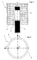
- Figur 1
- eine seitliche Draufsicht auf einen Kommutator in Verbindung mit einer Bürste (teilweise geschnitten),
- Figur 2
- eine Draufsicht auf die Bürste und den Kommutator von oben,
- Figur 3
- eine schematischer Schnitt quer zur Drehachse des Kommutators,
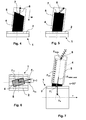
- Figur 4, 5
- längs geschnittene Bürsten, jeweils mit einer schematisch dargestellten Lamelle in Kontakt,
- Figur 6
- ein Ansicht einer Kontaktfläche einer Bürste auf einem Kommutator und
- Figur 7
- eine Schnittansicht eines Kommutators entlang seiner Drehachse mit aufgesetzter Bürste und Darstellung der Kraftvektoren.
- Ein Kommutator 1 (Fig. 1 bis 3) einer elektro-dynamischen Maschine, insbesondere eines Elektromotors, weist eine Vielzahl von Lamellen 2 auf, die sich auf der äußeren Mantelfläche des Kommutators 1 in Längsrichtung, d. h. parallel zur Drehachse x des Motors, erstrecken. Die Lamellen 2 sind durch Schlitze oder Nuten 3 von einander getrennt. In y-Richtung liegt eine Bürste 4 auf den Lamellen 2 auf. Die Bürste 4 wird von einer Bürstenführung 5 gegen die Lamellen 2 gedrückt. Die Anpresskraft wird durch ein elastisches Element, insbesondere eine Feder 6 (Fig. 4, 5), auf die Lamellen 2 ausgeübt.
- Wie in Fig. 1 dargestellt, ist die Bürste 4 in der xy-Ebene um die z-Achse gedreht, so dass die Bürste 4 unter einer Neigungsrichtung w gegen die Lamellen 2 gedrückt wird. Gegenüber der Richtung w ist eine Federkraft FFeder in der xy-Ebene weiter gekippt. Die Feder 6 (Fig. 4, 5) drückt die Bürste 4 gegen die Lamellen 2 des Kommutators 1.
- Die Federkraft FFeder (Fig. 1) lässt sich somit in zwei Komponenten zerlegen: eine axiale Komponente FFeder, axial und eine Komponente FFeder, T. Diese gewährleistet die stabile Lage der Bürste 4 in der Bürstenführung 5.
- Die Kraft FFeder, axial, mit der die Bürste 4 gegen die Lamellen 2 drückt, lässt sich ihrerseits wieder in zwei Komponenten zerlegen: die Kraft FN, die Normalkomponente, die den Kontakt zur Kommutatoroberfläche gewährleistet, und die Kraft FT, die die stabile Lage der Bürste 4 in der Bürstenführung 5 hervorruft.
- Eine Zerlegung der Federkraft FFeder, axial lässt sich entweder dadurch erreichen, dass die Feder, wie in Fig. 1 oder 5 dargestellt, gegenüber der Richtung w geneigt ist, oder dadurch, dass die von den Lamellen 2 abgewandte Stirnfläche 7 gegenüber der Neigungsrichtung w der Bürste 4 nicht unter einem rechten Winkel, wie in Fig. 5 dargestellt, sondern unter einem stumpfen Winkel steht. Auch in diesem Fall lässt sich die Federkraft FFeder in zwei Komponenten zerlegen: eine, die die Bürste 4 gegen die innere Wandung der Bürstenführung 5 drückt (FNB, Fig.7), und eine, die die Bürste gegen die Lamellen 2 drückt (FN).
- Die Erfindung lässt sich einsetzen, unabhängig davon, ob die Bürste 4 lediglich in der xy-Ebene um die z-Achse gedreht ist, wie in Fig. 1 dargestellt, oder ob die Bürstenkanten zusätzlich auch gegenüber der x-Richtung geneigt sind. Diese Neigung ist durch einen nicht rechteckförmigen Querschnitt der Bürste oder durch die Verkippung der rechteckförmigen Bürste, wie in Fig. 6 dargestellt, realisierbar. In diesem Fall lässt sich die Tangentialkomponente FT der Federkraft FFeder, axial zusätzlich in zwei Komponenten FTX und FTY aufteilen.
- Im Beispiel der Fig. 7 ist der Winkel α zwischen der Querrichtung der Hauptebene der Bürstenkontaktfläche zum Kontaktradius am Kollektor gleich 90°. In jedem Fall drückt eine Komponente FNB, wie in Fig. 7 dargestellt, gegen die innere Wandung der Bürstenführung 5, wodurch eine ganzflächige wärmeleitende Verbindung zwischen der Bürste 4 und der Bürstenführung 5 hergestellt ist, so dass eine gute Ableitung der bei der Reibung zwischen der Bürste 4 und den Lamellen 2 entstehenden Wärme garantiert wird. Durch die stabile Lagerung der Bürste 4 werden auch Geräusche weitgehend unterdrückt. Au-ßerdem wird die Entstehung von einen hohen Verschleiß verursachenden und zu Energieverlust führenden Lichtbögen vermieden. Es wird eine konstante, nicht schwingende Halterung der Bürste 4 in der Bürstenhalterung 5 gewährleistet. Dadurch, dass das punkt- und linienförmige Anliegen der Bürste in der Bürstenführung und damit die hohen Kontaktkräfte zwischen der Bürste und der Bürstenführung reduziert bzw. vermieden werden, werden auch die Querströme in der Bürste reduziert bzw. vermieden.
- Anstelle der Feder 6 lässt sich auch ein anderes elastisches Element, beispielsweise aus Gummi oder aus einem elastischen Kunststoff, einsetzen.
Claims (6)
- In einer Bürstenführung (5) angeordnete Bürste (4) für eine mechanisch kommutierte dynamo-elektrische Maschine, insbesondere für einen Elektromotor, zur Herstellung und/oder Aufrechterhaltung eines elektrischen Kontaktes oder Gleitkontaktes zwischen einem feststehenden ersten Teil, beispielsweise einer Stromversorgung, und einem Kommutator (1) mit Lamellen (2), wobei ein elastisches Element (6) die Bürste (4) gegen die Lamellen (2) drückt, indem die Bürste (4) gegenüber der Drehachse (x) des Kommutators (1) unter einem vom 90°-Winkel abweichenden Winkel in einer Neigungsrichtung (w) angeordnet ist, und indem das elastische Element (6) unter einer von der Neigungsrichtung (w) der Bürste (4) abweichenden Richtung und unter einem von der Senkrechten auf die dem Kommutator (1) zugewandte Stirnfläche der Bürste (4) abweichenden Winkel eine Federkraft (FFeder) auf die Bürste (4) ausübt, wobei die Federkraft (FFeder) aus zwei Komponenten besteht, einer axiale Kraftkomponente (FFeder, axial) und einer Kraftkomponente (FFeder, T), die eine stabile Lage der Bürste (4) in der Bürstenführung (5) gewährleistet, und wobei die axiale Kraftkomponente (FFeder, axial) mit der die Bürste (4) gegen die Lamellen (2) drückt ihrerseits aus zwei Komponenten besteht, einer Normalkomponente (FN), die den Kontakt zur Kommutatoroberfläche gewährleistet, und einer Kraftkomponente (FT), die eine stabile Lage der Bürste (4) in der Bürstenführung (5) gewährleistet und wobei die Bürste (4) rechteckförmig ist, dadurch gekennzeichnet, dass die Kraftkomponenten (FFeder, T, FT) der Federkraft (FFeder), die die stabile Lage der Bürste (4) in der Bürstenführung (5) gewährleisten, ausschließlich auf eine der Schmalseiten der Bürste (4) gerichtet sind, so dass die Bürste (4) mit dieser Schmalseite an der Bürstenführung (5) anliegt.
- Bürste nach Anspruch 1, dadurch gekennzeichnet, dass die Bürste (4) zusammen mit der Bürstenführung (5) drehbar gegenüber den Lamellen (2) des Kommutators (1) angeordnet ist, so dass eine einfache Ein- und Verstellung eines Schrägstellungswinkels (β) zwischen der Bürste (4) und den Lamellen sowie den Schlitzen des Kommutators (1) möglich ist.
- Bürste nach einem der Ansprüche 1 oder 2, dadurch gekennzeichnet, dass die Bürste (4) zusammen mit der Bürstenführung (5) um einen Schrägstellungswinkel (β) derart verdreht ist, dass keine Kante der Bürste (4) parallel zur Drehachse (x) liegt.
- Bürste nach einem der Ansprüche 1 bis 3, dadurch gekennzeichnet, dass sie gegenüber der radialen Richtung der Lamellen (2) geneigt angeordnet ist
- Bürste nach einem der Ansprüche 1 bis 4, dadurch gekennzeichnet, dass das elastische Element eine Feder (6) ist.
- Bürste nach Anspruch 5, dadurch gekennzeichnet, dass die Feder (6) unter der von der Neigungsrichtung (w) der Bürste (4) abweichenden Richtung die Federkraft (FFeder) auf die Bürste (4) ausübt, indem die Feder gegenüber der Neigungsrichtung (w) geneigt ist oder indem die von den Lamellen (2) abgewandte Stirnfläche (7) der Bürste (4) gegenüber der Neigungsrichtung (w) der Bürste (4) nicht unter einem rechten Winkel steht.
Priority Applications (1)
| Application Number | Priority Date | Filing Date | Title |
|---|---|---|---|
| SI200330790T SI1537635T1 (sl) | 2002-09-06 | 2003-08-28 | Krtačka za dinamoelektrični stroj |
Applications Claiming Priority (3)
| Application Number | Priority Date | Filing Date | Title |
|---|---|---|---|
| DE10241382A DE10241382A1 (de) | 2002-09-06 | 2002-09-06 | Bürste für eine dynamo-elektrische Maschine |
| DE10241382 | 2002-09-06 | ||
| PCT/EP2003/009639 WO2004023609A1 (de) | 2002-09-06 | 2003-08-28 | Bürste für eine dynamo-elektrische maschine |
Publications (2)
| Publication Number | Publication Date |
|---|---|
| EP1537635A1 EP1537635A1 (de) | 2005-06-08 |
| EP1537635B1 true EP1537635B1 (de) | 2007-02-14 |
Family
ID=31724454
Family Applications (1)
| Application Number | Title | Priority Date | Filing Date |
|---|---|---|---|
| EP03793775A Expired - Lifetime EP1537635B1 (de) | 2002-09-06 | 2003-08-28 | Bürste für eine dynamo-elektrische maschine |
Country Status (6)
| Country | Link |
|---|---|
| EP (1) | EP1537635B1 (de) |
| CN (1) | CN100385750C (de) |
| AT (1) | ATE354194T1 (de) |
| DE (2) | DE10241382A1 (de) |
| SI (1) | SI1537635T1 (de) |
| WO (1) | WO2004023609A1 (de) |
Families Citing this family (7)
| Publication number | Priority date | Publication date | Assignee | Title |
|---|---|---|---|---|
| DE102008041533A1 (de) * | 2008-08-26 | 2010-03-04 | Robert Bosch Gmbh | Elektrische Maschine sowie Anordnung bestehend aus einer elektrischen Schleifbürste und einem Führungselement für eine Schleifbürste |
| DE102009001714A1 (de) * | 2009-03-20 | 2010-09-23 | Robert Bosch Gmbh | Elektrischer Antriebsmotor, insbesondere für ein Aggregat in einem Kraftfahrzeug |
| DE102009025340B4 (de) * | 2009-06-18 | 2011-02-24 | Metabowerke Gmbh | Elektrohandwerkzeuggerät mit Schleifbürsten |
| EP2582025A2 (de) * | 2011-10-11 | 2013-04-17 | Steering Solutions IP Holding Corporation | Bürstensystem für einen Kommutatormotor |
| DE102014225515A1 (de) * | 2014-12-11 | 2016-06-16 | Robert Bosch Gmbh | Kommutierungseinrichtung für eine elektrische Maschine |
| DE102016213653A1 (de) * | 2016-07-26 | 2018-02-01 | Schunk Hoffmann Carbon Technology Ag | Ableiteinrichtung zur Ableitung elektrischer Störungen |
| FR3087593B1 (fr) * | 2018-10-17 | 2022-10-14 | Valeo Systemes Thermiques | Ensemble pour un pulseur de vehicule automobile |
Family Cites Families (12)
| Publication number | Priority date | Publication date | Assignee | Title |
|---|---|---|---|---|
| DE303354C (de) * | ||||
| DE698701C (de) * | 1939-01-18 | 1941-01-27 | Ringsdorff Werke Komm Ges | Buerstenschraeghalter fuer elektrische Maschinen |
| US2615939A (en) * | 1950-10-02 | 1952-10-28 | Westinghouse Electric Corp | Brush mechanism |
| BE553616A (de) * | 1956-01-02 | 1957-01-15 | ||
| DE1538961A1 (de) * | 1966-12-14 | 1970-04-09 | N Izsledovatelski I P Konstruk | Staenderloser Kommutator-Elektromotor mit axial geneigten Buersten |
| DE1613371A1 (de) * | 1967-02-21 | 1970-05-21 | Siemens Ag | Buerstenhalter mit rohrfoermiger Buerstenfuehrung |
| DE3022991A1 (de) * | 1980-06-20 | 1982-01-14 | Robert Bosch Gmbh, 7000 Stuttgart | Stromuebertragungseinrichtung |
| FR2520942A1 (fr) * | 1982-01-29 | 1983-08-05 | Thomson Brandt | Moteur electrique a collecteur muni de porte-balais a deux positions |
| US5049772A (en) * | 1990-09-10 | 1991-09-17 | United Technologies Corporation | Reduced noise commutator |
| GB9509869D0 (en) * | 1995-05-16 | 1995-07-12 | Johnson Electric Sa | Brush assembly for an electric motor |
| US5907207A (en) * | 1997-11-07 | 1999-05-25 | Ryobi, Ryobi North America, Inc. | Constant force brush spring arrangement for electric motor |
| DE19755507A1 (de) * | 1997-12-13 | 1999-06-17 | Fhp Motors Gmbh | Bürstenhalterung für mechanisch kommutierte Elektromotoren |
-
2002
- 2002-09-06 DE DE10241382A patent/DE10241382A1/de not_active Withdrawn
-
2003
- 2003-08-28 AT AT03793775T patent/ATE354194T1/de not_active IP Right Cessation
- 2003-08-28 CN CNB038210630A patent/CN100385750C/zh not_active Expired - Fee Related
- 2003-08-28 WO PCT/EP2003/009639 patent/WO2004023609A1/de not_active Ceased
- 2003-08-28 DE DE50306529T patent/DE50306529D1/de not_active Expired - Lifetime
- 2003-08-28 EP EP03793775A patent/EP1537635B1/de not_active Expired - Lifetime
- 2003-08-28 SI SI200330790T patent/SI1537635T1/sl unknown
Also Published As
| Publication number | Publication date |
|---|---|
| CN1679215A (zh) | 2005-10-05 |
| DE50306529D1 (de) | 2007-03-29 |
| DE10241382A1 (de) | 2004-03-18 |
| EP1537635A1 (de) | 2005-06-08 |
| WO2004023609A1 (de) | 2004-03-18 |
| CN100385750C (zh) | 2008-04-30 |
| ATE354194T1 (de) | 2007-03-15 |
| SI1537635T1 (sl) | 2007-08-31 |
Similar Documents
| Publication | Publication Date | Title |
|---|---|---|
| EP1537635B1 (de) | Bürste für eine dynamo-elektrische maschine | |
| DE69826297T2 (de) | Drehende elektrische maschine | |
| DE69834222T2 (de) | Bürstenanordnung für eine dynamoelektrische Maschine | |
| EP1900078B1 (de) | Nutverschluss | |
| EP1711985B1 (de) | Bürstenköcher für eine Dynamo-elektrische Maschine | |
| EP1358698B1 (de) | Stromübertragungsanordnung | |
| EP1797628B1 (de) | Elektromotor und elektrische antriebseinheit für kraftfahrzeuge | |
| EP0966072B1 (de) | Stromwendevorrichtung für elektrische Maschinen | |
| DE9106141U1 (de) | Elektromotor | |
| EP2409386A2 (de) | Elektrischer antriebsmotor, insbesondere für ein aggregat in einem kraftfahrzeug | |
| DE102010042697A1 (de) | Kommutatormotor | |
| DE102010042699A1 (de) | Kommutatormotor | |
| DE4141307C2 (de) | Bürstenführungsanordnung für eine elektrische Maschine | |
| WO2000045474A1 (de) | Kohlebürste | |
| WO2008022631A1 (de) | Gleichstrommaschine | |
| EP2795743B1 (de) | Kommutatormotor | |
| EP2195890A1 (de) | Kohlebürstenanordnung für eine elektrische maschine | |
| DE102023129177B4 (de) | Bürstenmodule für Drehtische | |
| DE10058872A1 (de) | Bürste und Bürstenanordnung für eine dynamo-elektrische Maschine | |
| WO2006067097A1 (de) | Bürstenköcher für eine dynamo-elektrische maschine | |
| DE3836317A1 (de) | Buerstenanordnung fuer einen elektromotor | |
| DD225269A1 (de) | Kommutierungseinheit fuer elektrische motoren | |
| EP1770201A1 (de) | Schleifkontaktvorrichtung und Wäschetrockner mit einer solchen | |
| DE10058742A1 (de) | Bürste und Bürstenanordnung für eine dynamoelektrische Maschine | |
| DE10058873A1 (de) | Bürste und Bürstenanordnung für eine dynamo-elektrische Maschine |
Legal Events
| Date | Code | Title | Description |
|---|---|---|---|
| PUAI | Public reference made under article 153(3) epc to a published international application that has entered the european phase |
Free format text: ORIGINAL CODE: 0009012 |
|
| 17P | Request for examination filed |
Effective date: 20050406 |
|
| AK | Designated contracting states |
Kind code of ref document: A1 Designated state(s): AT BE BG CH CY CZ DE DK EE ES FI FR GB GR HU IE IT LI LU MC NL PT RO SE SI SK TR |
|
| GRAP | Despatch of communication of intention to grant a patent |
Free format text: ORIGINAL CODE: EPIDOSNIGR1 |
|
| GRAS | Grant fee paid |
Free format text: ORIGINAL CODE: EPIDOSNIGR3 |
|
| GRAA | (expected) grant |
Free format text: ORIGINAL CODE: 0009210 |
|
| AK | Designated contracting states |
Kind code of ref document: B1 Designated state(s): AT BE BG CH CY CZ DE DK EE ES FI FR GB GR HU IE IT LI LU MC NL PT RO SE SI SK TR |
|
| PG25 | Lapsed in a contracting state [announced via postgrant information from national office to epo] |
Ref country code: DK Free format text: LAPSE BECAUSE OF FAILURE TO SUBMIT A TRANSLATION OF THE DESCRIPTION OR TO PAY THE FEE WITHIN THE PRESCRIBED TIME-LIMIT Effective date: 20070214 Ref country code: IE Free format text: LAPSE BECAUSE OF FAILURE TO SUBMIT A TRANSLATION OF THE DESCRIPTION OR TO PAY THE FEE WITHIN THE PRESCRIBED TIME-LIMIT Effective date: 20070214 Ref country code: FI Free format text: LAPSE BECAUSE OF FAILURE TO SUBMIT A TRANSLATION OF THE DESCRIPTION OR TO PAY THE FEE WITHIN THE PRESCRIBED TIME-LIMIT Effective date: 20070214 Ref country code: NL Free format text: LAPSE BECAUSE OF FAILURE TO SUBMIT A TRANSLATION OF THE DESCRIPTION OR TO PAY THE FEE WITHIN THE PRESCRIBED TIME-LIMIT Effective date: 20070214 |
|
| REG | Reference to a national code |
Ref country code: GB Ref legal event code: FG4D Free format text: NOT ENGLISH |
|
| REG | Reference to a national code |
Ref country code: CH Ref legal event code: EP |
|
| GBT | Gb: translation of ep patent filed (gb section 77(6)(a)/1977) |
Effective date: 20070214 |
|
| REG | Reference to a national code |
Ref country code: RO Ref legal event code: EPE |
|
| REF | Corresponds to: |
Ref document number: 50306529 Country of ref document: DE Date of ref document: 20070329 Kind code of ref document: P |
|
| REG | Reference to a national code |
Ref country code: IE Ref legal event code: FG4D Free format text: LANGUAGE OF EP DOCUMENT: GERMAN |
|
| PG25 | Lapsed in a contracting state [announced via postgrant information from national office to epo] |
Ref country code: SE Free format text: LAPSE BECAUSE OF FAILURE TO SUBMIT A TRANSLATION OF THE DESCRIPTION OR TO PAY THE FEE WITHIN THE PRESCRIBED TIME-LIMIT Effective date: 20070514 |
|
| PG25 | Lapsed in a contracting state [announced via postgrant information from national office to epo] |
Ref country code: BG Free format text: LAPSE BECAUSE OF EXPIRATION OF PROTECTION Effective date: 20070515 |
|
| PG25 | Lapsed in a contracting state [announced via postgrant information from national office to epo] |
Ref country code: ES Free format text: LAPSE BECAUSE OF FAILURE TO SUBMIT A TRANSLATION OF THE DESCRIPTION OR TO PAY THE FEE WITHIN THE PRESCRIBED TIME-LIMIT Effective date: 20070525 |
|
| ET | Fr: translation filed | ||
| PG25 | Lapsed in a contracting state [announced via postgrant information from national office to epo] |
Ref country code: PT Free format text: LAPSE BECAUSE OF FAILURE TO SUBMIT A TRANSLATION OF THE DESCRIPTION OR TO PAY THE FEE WITHIN THE PRESCRIBED TIME-LIMIT Effective date: 20070716 |
|
| NLV1 | Nl: lapsed or annulled due to failure to fulfill the requirements of art. 29p and 29m of the patents act | ||
| REG | Reference to a national code |
Ref country code: IE Ref legal event code: FD4D |
|
| PLBE | No opposition filed within time limit |
Free format text: ORIGINAL CODE: 0009261 |
|
| STAA | Information on the status of an ep patent application or granted ep patent |
Free format text: STATUS: NO OPPOSITION FILED WITHIN TIME LIMIT |
|
| PG25 | Lapsed in a contracting state [announced via postgrant information from national office to epo] |
Ref country code: CZ Free format text: LAPSE BECAUSE OF FAILURE TO SUBMIT A TRANSLATION OF THE DESCRIPTION OR TO PAY THE FEE WITHIN THE PRESCRIBED TIME-LIMIT Effective date: 20070214 |
|
| 26N | No opposition filed |
Effective date: 20071115 |
|
| BERE | Be: lapsed |
Owner name: BSH BOSCH UND SIEMENS HAUSGERATE G.M.B.H. Effective date: 20070831 |
|
| REG | Reference to a national code |
Ref country code: CH Ref legal event code: PL |
|
| PG25 | Lapsed in a contracting state [announced via postgrant information from national office to epo] |
Ref country code: LI Free format text: LAPSE BECAUSE OF NON-PAYMENT OF DUE FEES Effective date: 20070831 Ref country code: MC Free format text: LAPSE BECAUSE OF NON-PAYMENT OF DUE FEES Effective date: 20070831 Ref country code: GR Free format text: LAPSE BECAUSE OF FAILURE TO SUBMIT A TRANSLATION OF THE DESCRIPTION OR TO PAY THE FEE WITHIN THE PRESCRIBED TIME-LIMIT Effective date: 20070515 Ref country code: CH Free format text: LAPSE BECAUSE OF NON-PAYMENT OF DUE FEES Effective date: 20070831 |
|
| PG25 | Lapsed in a contracting state [announced via postgrant information from national office to epo] |
Ref country code: BE Free format text: LAPSE BECAUSE OF NON-PAYMENT OF DUE FEES Effective date: 20070831 |
|
| PGFP | Annual fee paid to national office [announced via postgrant information from national office to epo] |
Ref country code: SI Payment date: 20080821 Year of fee payment: 6 |
|
| PG25 | Lapsed in a contracting state [announced via postgrant information from national office to epo] |
Ref country code: AT Free format text: LAPSE BECAUSE OF NON-PAYMENT OF DUE FEES Effective date: 20070828 |
|
| PGFP | Annual fee paid to national office [announced via postgrant information from national office to epo] |
Ref country code: SK Payment date: 20080708 Year of fee payment: 6 Ref country code: FR Payment date: 20080818 Year of fee payment: 6 Ref country code: IT Payment date: 20080825 Year of fee payment: 6 Ref country code: RO Payment date: 20080825 Year of fee payment: 6 |
|
| PGFP | Annual fee paid to national office [announced via postgrant information from national office to epo] |
Ref country code: GB Payment date: 20080822 Year of fee payment: 6 |
|
| PG25 | Lapsed in a contracting state [announced via postgrant information from national office to epo] |
Ref country code: EE Free format text: LAPSE BECAUSE OF FAILURE TO SUBMIT A TRANSLATION OF THE DESCRIPTION OR TO PAY THE FEE WITHIN THE PRESCRIBED TIME-LIMIT Effective date: 20070214 |
|
| PG25 | Lapsed in a contracting state [announced via postgrant information from national office to epo] |
Ref country code: CY Free format text: LAPSE BECAUSE OF FAILURE TO SUBMIT A TRANSLATION OF THE DESCRIPTION OR TO PAY THE FEE WITHIN THE PRESCRIBED TIME-LIMIT Effective date: 20070214 |
|
| PG25 | Lapsed in a contracting state [announced via postgrant information from national office to epo] |
Ref country code: LU Free format text: LAPSE BECAUSE OF NON-PAYMENT OF DUE FEES Effective date: 20070828 |
|
| PG25 | Lapsed in a contracting state [announced via postgrant information from national office to epo] |
Ref country code: HU Free format text: LAPSE BECAUSE OF FAILURE TO SUBMIT A TRANSLATION OF THE DESCRIPTION OR TO PAY THE FEE WITHIN THE PRESCRIBED TIME-LIMIT Effective date: 20070815 |
|
| GBPC | Gb: european patent ceased through non-payment of renewal fee |
Effective date: 20090828 |
|
| PG25 | Lapsed in a contracting state [announced via postgrant information from national office to epo] |
Ref country code: RO Free format text: LAPSE BECAUSE OF NON-PAYMENT OF DUE FEES Effective date: 20090828 |
|
| REG | Reference to a national code |
Ref country code: SK Ref legal event code: MM4A Ref document number: E 2045 Country of ref document: SK Effective date: 20090828 |
|
| REG | Reference to a national code |
Ref country code: FR Ref legal event code: ST Effective date: 20100430 |
|
| PG25 | Lapsed in a contracting state [announced via postgrant information from national office to epo] |
Ref country code: SK Free format text: LAPSE BECAUSE OF NON-PAYMENT OF DUE FEES Effective date: 20090828 |
|
| REG | Reference to a national code |
Ref country code: SI Ref legal event code: KO00 Effective date: 20100416 |
|
| PG25 | Lapsed in a contracting state [announced via postgrant information from national office to epo] |
Ref country code: FR Free format text: LAPSE BECAUSE OF NON-PAYMENT OF DUE FEES Effective date: 20090831 |
|
| PG25 | Lapsed in a contracting state [announced via postgrant information from national office to epo] |
Ref country code: SI Free format text: LAPSE BECAUSE OF NON-PAYMENT OF DUE FEES Effective date: 20090829 |
|
| PG25 | Lapsed in a contracting state [announced via postgrant information from national office to epo] |
Ref country code: GB Free format text: LAPSE BECAUSE OF NON-PAYMENT OF DUE FEES Effective date: 20090828 |
|
| PG25 | Lapsed in a contracting state [announced via postgrant information from national office to epo] |
Ref country code: IT Free format text: LAPSE BECAUSE OF NON-PAYMENT OF DUE FEES Effective date: 20090828 |
|
| PGFP | Annual fee paid to national office [announced via postgrant information from national office to epo] |
Ref country code: DE Payment date: 20110831 Year of fee payment: 9 Ref country code: TR Payment date: 20110818 Year of fee payment: 9 |
|
| PG25 | Lapsed in a contracting state [announced via postgrant information from national office to epo] |
Ref country code: DE Free format text: LAPSE BECAUSE OF NON-PAYMENT OF DUE FEES Effective date: 20130301 |
|
| REG | Reference to a national code |
Ref country code: DE Ref legal event code: R119 Ref document number: 50306529 Country of ref document: DE Effective date: 20130301 |
|
| PG25 | Lapsed in a contracting state [announced via postgrant information from national office to epo] |
Ref country code: TR Free format text: LAPSE BECAUSE OF NON-PAYMENT OF DUE FEES Effective date: 20120828 |