EP1537697B1 - Procede et dispositif d'identification rapide d'erreurs de transmission - Google Patents
Procede et dispositif d'identification rapide d'erreurs de transmission Download PDFInfo
- Publication number
- EP1537697B1 EP1537697B1 EP03793628A EP03793628A EP1537697B1 EP 1537697 B1 EP1537697 B1 EP 1537697B1 EP 03793628 A EP03793628 A EP 03793628A EP 03793628 A EP03793628 A EP 03793628A EP 1537697 B1 EP1537697 B1 EP 1537697B1
- Authority
- EP
- European Patent Office
- Prior art keywords
- sequence
- transmission
- received
- voltage
- bit
- Prior art date
- Legal status (The legal status is an assumption and is not a legal conclusion. Google has not performed a legal analysis and makes no representation as to the accuracy of the status listed.)
- Expired - Lifetime
Links
- 230000005540 biological transmission Effects 0.000 title claims abstract description 38
- 238000000034 method Methods 0.000 title claims abstract description 18
- 238000001514 detection method Methods 0.000 title abstract description 14
- 238000004891 communication Methods 0.000 description 4
- 238000011156 evaluation Methods 0.000 description 3
- 230000010354 integration Effects 0.000 description 3
- 230000001419 dependent effect Effects 0.000 description 2
- 238000012544 monitoring process Methods 0.000 description 2
- 125000004122 cyclic group Chemical group 0.000 description 1
- 238000011835 investigation Methods 0.000 description 1
- 238000012806 monitoring device Methods 0.000 description 1
- 239000007787 solid Substances 0.000 description 1
- 238000013519 translation Methods 0.000 description 1
- 238000012795 verification Methods 0.000 description 1
Images

Classifications
-
- H—ELECTRICITY
- H04—ELECTRIC COMMUNICATION TECHNIQUE
- H04L—TRANSMISSION OF DIGITAL INFORMATION, e.g. TELEGRAPHIC COMMUNICATION
- H04L25/00—Baseband systems
- H04L25/38—Synchronous or start-stop systems, e.g. for Baudot code
- H04L25/40—Transmitting circuits; Receiving circuits
- H04L25/49—Transmitting circuits; Receiving circuits using code conversion at the transmitter; using predistortion; using insertion of idle bits for obtaining a desired frequency spectrum; using three or more amplitude levels ; Baseband coding techniques specific to data transmission systems
- H04L25/4906—Transmitting circuits; Receiving circuits using code conversion at the transmitter; using predistortion; using insertion of idle bits for obtaining a desired frequency spectrum; using three or more amplitude levels ; Baseband coding techniques specific to data transmission systems using binary codes
-
- H—ELECTRICITY
- H04—ELECTRIC COMMUNICATION TECHNIQUE
- H04L—TRANSMISSION OF DIGITAL INFORMATION, e.g. TELEGRAPHIC COMMUNICATION
- H04L1/00—Arrangements for detecting or preventing errors in the information received
- H04L1/20—Arrangements for detecting or preventing errors in the information received using signal quality detector
-
- H—ELECTRICITY
- H04—ELECTRIC COMMUNICATION TECHNIQUE
- H04L—TRANSMISSION OF DIGITAL INFORMATION, e.g. TELEGRAPHIC COMMUNICATION
- H04L1/00—Arrangements for detecting or preventing errors in the information received
- H04L1/24—Testing correct operation
- H04L1/245—Testing correct operation by using the properties of transmission codes
Definitions
- the invention relates to a method and a device for the rapid detection of transmission errors in a digital transmission of data or messages.
- the so-called Xerxes method for a digital data transmission is for example from US 4,234,897 known.
- the data or messages to be transmitted are digital or digitized for digital transmission.
- the digital or digitized message is subdivided into certain bit sequences, each of which is assigned a mean-free sequence of high or low level signals.
- the signals each have a minimum level duration Tmin and a maximum level duration Tmax.
- a fast detection of transmission errors is important for increasing reliability, especially in safety-relevant applications.
- a CRC Cyclic Redundancy Check
- a CRC Cyclic Redundancy Check
- ISO / OSI levels For example, the verification takes place at the application level, which is why such an error checking system is very slow.
- the invention is therefore based on the technical problem of providing a method and a device by which a fast detection of transmission errors is possible at the lowest communication level.
- the method and apparatus of error detection exploit the phenomena of digital transmission of messages or data by determining the freedom of sequence of sequences.
- the integral of the signals results in a DC voltage of zero volts resulting from the sequence. If sequences are incomplete and / or transmitted incorrectly, residual stresses may remain. The corresponding messages can then be marked.
- the level duration is determined and used for error detection.
- a level duration i. the duration in which a signal of a high or a low level is applied varies.
- the level duration depends both on the currently transmitted sequence and on the previous one. However, the level duration must always be within the interval [Tmin, Tmax] in the case of error-free data transmission. If there are signals which are shorter than Tmin or longer than Tmax, an error occurs in the message transmission and the message is also marked as invalid.
- an evaluation of the average freedom and / or the level duration is performed directly on the physical transmission medium, for example a data bus.
- the error detection can thus take place at the lowest communication level and is independent of other known methods of monitoring.
- a content evaluation of the data is not necessary, so that no data overhead arises.
- the evaluation on the transmission medium can take place at a receiver of the message or by a monitoring device independent of the receiver.
- a mean value freedom is determined by decoding the received signals into a receive bit sequence, combining individual bits of the receive bit sequence into at least one receive sequence, and examining the receive sequence for DC freedom.
- the DC freedom at the end of a sequence can be detected by a suitable sensor, such as a voltmeter, and / or by integration of the received signals can be determined.
- the integration can be implemented hardware and / or software technology.
- the messages are encoded and decoded with a xerxes format and the receive sequence conforms to the encoding rules.
- the Xerxes method for DC-free coding for data transmission is from the US 4,234,897 known.
- the Xerxes code generates a transmission signal from which the original signal can be encoded. Every potential jump in a cell center is recognized as a logical one. A potential jump at the beginning of such a bit cell, which is followed by a bit cell without potential jump, is also considered a logical one in each bit cell. Every other potential jump at the bit cell start is decoded as logical zero. All other cells in which there are no potential jumps are also rated with a logical zero.
- the received signals are combined into receive sequences at the receiver and / or in the monitoring unit, which correspond to the coding rules. Hurt the associated received signals the coding rules, so there is a transmission error.
- the DC voltage freedom is checked by determining a residual voltage applied to a transmission medium.
- a transmission medium for example, a bus system with different nodes is used.
- a communication sequence is predetermined on the basis of periods during which the individual nodes are allowed to send. The length of these time periods is divisible into complete Xerxes sequences.
- IFG Inter Frame Gap
- the received data or messages are processed.
- no defined signal is given to the bus.
- the voltage on the bus is therefore zero volts, provided that the Xerxes sequences have been transmitted correctly and completely. If the bus voltage deviates significantly from this value, at least one of the sequences was transmitted incorrectly and / or disturbed.
- an occurring residual stress is reduced within the IFG. This is done e.g. by suitable RC elements. This avoids the propagation of errors over several periods of time.
- the level duration and / or the residual voltage are checked within a tolerance field. Low residual voltages can also occur if a message can not be subdivided into defined bit sequences without a remainder.
- Toleranzfeldem which are dependent on the level of the signal level for checking the residual voltage, for example, therefore makes sense, so that an error is not erroneously displayed.
- a membership is set in the event of a faulty transmission.
- a faulty node can be identified, but this may continue to participate in a communication under certain circumstances.
- Fault detection increases the reliability by realizing a fast reaction to faults and thus a high availability of the systems.
- the error detection is preferably used in safety-critical applications, such as X-by-wire systems. However, the use is not limited to such applications.
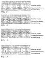
- Fig. 2 shows an encoding of a message 1A with the Xerxes format.
- 1B the message is subdivided into defined bit sequences a, b, c, 00.
- the bit sequences are assigned sequences of signals according to FIG. 1C.
- 1D shows the integral of sequences 1C. The numbering of the bit cells is shown in the first line.
- a logical one (1-bit) is transmitted as a potential jump in one (bit) cell center, a logical zero (0-bit) as a potential jump at a (bit) cell start.
- 1 bits do not represent a DC problem. If the number of 0 bits is even, there is likewise no DC problem.
- bit-string types In order to compensate for an imbalance that arises with an odd number of 0-bits, at least four bit-string types are introduced: a bit-string type (00) in which 0-bits are combined in pairs, a bit-string type (a), which consists of a is any number of 1-bits but has no 0-bits, a bit-string type (b) with an even number of 1-bits between two 0-bits and a bit-string type (c) with an odd number of 1- Bits between two 0-bits.
- bitstream types are all DC-free because they have either no or even number of 0-bits.
- Line 1 B shows a division of the message into the four bit sequence types.
- the sequence reaches a logical zero after an even number of 1-bit cells (this corresponds to bit string type (b)), the subsequent logical zero is encoded by a potential jump at the beginning of the cell.
- each sequence of even number of 1-bit cells framed by each 0-bit cell is free of DC components.
- the 1-bit cell is marked at the end of an odd 1-bit sequence by a potential jump in the middle of the cell and the potential jump for the following 0-bit cell is suppressed, then again produces a mean-free signal.
- the level durations are a minimum of 1T and a maximum of 2.5T, where T is the logical bit duration of an associated controller.
- the DC freedom of the sequences is Fig. 2 Refer to curve 1D. The integral over each sequence is zero.
- Every potential jump in a cell center is recognized as a logical one.
- a potential jump at the beginning of such a bit cell, which is followed by a potential jump is considered a logical one in each of the two bit cells.
- a potential jump at the beginning followed by 2.5 bit cells at the same level and 1.5 bit cells at the opposite level is considered logical one in the first three bit cells followed by a logical zero.
- a potential jump at the beginning of the cell followed by two bit cells at the same level, 2.5 bit cells at the opposite level and 1.5 bit cells at the original level corresponds to five logical ones followed by a zero.
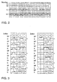
- the Fig. 1.1-1.4 show error considerations.
- a digital message a division of the message into bit sequence types and the associated error-free sequences are shown. It is assumed that in the case of a serial transmission of a message, the signal of a bitcell is incorrectly accepted by a potential jump occurring in the middle of the cell, or that the correct potential jump is registered late. The errors are marked by an arrow. The potential jump shifts from the cell center to the posterior cell edge. Resulting "translation errors" are considered, as well as any resulting errors.
- a message decoded from the errored sequence is shown.
- the solid bars under the bit pattern of the inverse transform represent bit strings according to bit string types a, b, c, 00.
- the position at which the error is detected is marked by an asterisk *.
- Fig. 1.1 leads the false registered potential jump at the beginning of the cell to a receive bit of only T / 2. This can not be interpreted by a decoder and leads to an error message. However, there are no subsequent errors.
- Fig. 1.2 leads the incorrectly transmitted signal in the bit cell 2 to a deviating from the coding assignment of the received bits to bit string types.
- the Xerxes format prescribes a different bit pattern for the signals of the bit cells 13 to 18 than the received bit pattern.
- the received bit pattern is not DC-free. This allows error detection. However, there are also no consequential errors.
- Fig. 1.3 a fault is assumed which leads erroneously to a potential jump in the cell center of cell 3. Subsequent errors do not occur.
- the Xerxes format writes as in Fig. 2.2 for the signals of the bit cells 9 and 10, a different bit pattern before whereby an error detection is possible.
- Fig. 1.4 a faulty transmission in cell 4 is shown.
- This error results in a signal with level duration T / 2.
- an error message must be issued immediately because of this condition prohibited in xerxes. Since the sequences are interpreted in a predictive manner in Xerxes format (maximum 2.5T), this error is detected in good time before further decoding steps. Similarly, signals that begin in the middle of a cell expect a potential jump after 2T at the latest. If this is not done, there is an error.
- Analogous to the Fig. 1.1 to 1.4 can detect errors in other cells. Only an error in cells 23 and 24 is not recognizable by a violation of the Xerxes format. However, such errors can be identified by the remaining residual voltage on the transmission medium.
- Fig. 3 shows a study on DC freedom.
- bit sequences BF and associated sequences S are shown.
- This residual stress can, as in Fig. 3 is maximum, assume the value of the integration over a bit cell duration.
- Residual voltage messages are indicated by an X. Remaining residual voltage must be counteracted in subsequent transmission pauses so as to minimize any influence on subsequent transfers.
Landscapes
- Engineering & Computer Science (AREA)
- Computer Networks & Wireless Communication (AREA)
- Signal Processing (AREA)
- Physics & Mathematics (AREA)
- Spectroscopy & Molecular Physics (AREA)
- Quality & Reliability (AREA)
- Small-Scale Networks (AREA)
- Detection And Prevention Of Errors In Transmission (AREA)
- Arrangements For Transmission Of Measured Signals (AREA)
Claims (18)
- Procédé de transmission d'au moins un message numérique et/ou numérisé, le message étant divisé en successions de bits définies, une séquence de signaux sans courant continu étant associée à une succession de bits de niveau bas ou élevé et la durée d'un niveau étant comprise dans un intervalle [Tmin, Tmax] donné, caractérisé en ce qu'on détermine l'absence de tension continue sur au moins une séquence pour identifier les erreurs dans une transmission numérique.
- Procédé selon la revendication 1, caractérisé en ce qu'on détermine en outre la durée à un niveau donné d'un signal.
- Procédé selon la revendication 1 ou 2, caractérisé en ce qu'on analyse l'absence de tension continue et/ou la durée à un niveau donné directement sur le support de transmission physique.
- Procédé selon la revendication 1, 2 ou 3, caractérisé en ce que les signaux reçus sont décodés pour obtenir une succession de bits en réception, en ce que les différents bits de la succession de bits en réception sont regroupés pour former au moins une séquence de réception et en ce qu'on recherche dans la séquence de réception une absence de tension continue.
- Procédé selon la revendication 4, caractérisé en ce que les messages sont codés et décodés au format Xerxes et que la séquence de réception est conforme aux règles de codage Xerxes.
- Procédé selon l'une quelconque des revendications 1 à 5, caractérisé en ce qu'on détermine une tension résiduelle sur le support de transmission.
- Procédé selon l'une quelconque des revendications précédentes, caractérisé en ce que la transmission est réalisée par l'intermédiaire d'un système de bus à commande temporelle et en ce qu'une tension résiduelle est résorbée pendant un intervalle inter-trame (Inter Frame Gap).
- Procédé selon l'une quelconque des revendications précédentes, caractérisé en ce que la durée autorisée à un niveau donné et/ou la tension résiduelle autorisée se situent dans une plage de tolérances donnée.
- Procédé selon l'une quelconque des revendications précédentes, caractérisé en ce qu'une appartenance (membership) est établie en cas de transmission erronée afin de repérer un noeud défectueux dans un système de bus.
- Dispositif de transmission d'au moins un message numérique et/ou numérisé sur un support de transmission, composé d'au moins un moyen de codage configuré de telle sorte que le message est divisé en successions de bits définies et qu'une séquence de signaux sans courant continu est associée à une succession de bits de niveau bas ou élevé et que la durée d'un niveau est située dans un intervalle [Tmin, Tmax], caractérisé en ce qu'au moins un moyen de détection et/ou de traitement est prévu pour déterminer les erreurs dans une transmission numérique par détermination d'une absence de tension continue dans au moins une séquence.
- Dispositif selon la revendication 10, caractérisé en ce que le moyen de détection et/ou de traitement détermine en outre la durée à un niveau donné d'au moins un signal.
- Dispositif selon la revendication 10 ou 11, caractérisé en ce que le moyen de détection et/ou de traitement est relié de façon interactive au support de transmission physique.
- Dispositif selon la revendication 10, 11 ou 12, caractérisé en ce qu'au moins un moyen de décodage est prévu, celui-ci décodant les signaux reçus en une succession de bits en réception et regroupant les différents bits de la succession de bits en réception pour former au moins une séquence de réception et en ce que le moyen de détection et/ou de traitement recherche l'absence de tension continue sur la séquence de réception.
- Dispositif selon la revendication 13, caractérisé en ce que les messages sont codés et décodés au moyen du format Xerxes et en ce que la séquence de réception est conforme aux règles de codage Xerxes.
- Dispositif selon l'une quelconque des revendications 10 à 14, caractérisé en ce que le moyen de détection et/ou de traitement détermine la présence d'une tension résiduelle sur le support de transmission.
- Dispositif selon l'une quelconque des revendications 10 à 15, caractérisé en ce que le support de transmission prend la forme d'un système de bus à commande temporelle et en ce que le dispositif comprend des moyens permettant de résorber une tension résiduelle pendant un intervalle inter-trame.
- Dispositif selon l'une quelconque des revendications 10 à 16, caractérisé en ce que la durée autorisée à un niveau donné et/ou la tension résiduelle autorisée se situent dans une plage de tolérances donnée.
- Dispositif selon l'une quelconque des revendications 10 à 17, caractérisé en ce qu'une appartenance est établie à l'aide d'un moyen de traitement et/ou de transmission en cas de transmission erronée afin de repérer un noeud défectueux dans un système de bus.
Applications Claiming Priority (3)
| Application Number | Priority Date | Filing Date | Title |
|---|---|---|---|
| DE10244066A DE10244066A1 (de) | 2002-09-06 | 2002-09-06 | Verfahren und Vorrichtung zur schnellen Erkennung von Übertragungsfehlern |
| DE10244066 | 2002-09-06 | ||
| PCT/EP2003/008039 WO2004023707A1 (fr) | 2002-09-06 | 2003-07-23 | Procede et dispositif d'identification rapide d'erreurs de transmission |
Publications (2)
| Publication Number | Publication Date |
|---|---|
| EP1537697A1 EP1537697A1 (fr) | 2005-06-08 |
| EP1537697B1 true EP1537697B1 (fr) | 2009-01-28 |
Family
ID=31724840
Family Applications (1)
| Application Number | Title | Priority Date | Filing Date |
|---|---|---|---|
| EP03793628A Expired - Lifetime EP1537697B1 (fr) | 2002-09-06 | 2003-07-23 | Procede et dispositif d'identification rapide d'erreurs de transmission |
Country Status (4)
| Country | Link |
|---|---|
| EP (1) | EP1537697B1 (fr) |
| AT (1) | ATE422123T1 (fr) |
| DE (2) | DE10244066A1 (fr) |
| WO (1) | WO2004023707A1 (fr) |
Family Cites Families (8)
| Publication number | Priority date | Publication date | Assignee | Title |
|---|---|---|---|---|
| US4234897A (en) * | 1978-10-05 | 1980-11-18 | Ampex Corporation | DC Free encoding for data transmission |
| US4502142A (en) * | 1982-09-07 | 1985-02-26 | Lockheed Electronics Company, Inc. | Apparatus for detecting errors in a digital data stream encoded in a double density code |
| CA1273112A (fr) * | 1986-03-26 | 1990-08-21 | Ernst August Munter | Methode et appareil de transmission serie a decoupage en voies de donnees binaires a codage a redondance |
| FR2629963B1 (fr) * | 1988-04-12 | 1991-03-15 | Trt Telecom Radio Electr | Dispositif de mesure et d'annulation de la distorsion biaise des signaux binaires du type ne comportant pas de composante spectrale a la frequence zero |
| GB8912471D0 (en) * | 1989-05-31 | 1989-07-19 | Int Computers Ltd | Data transmission code |
| GB2247138B (en) * | 1990-06-29 | 1994-10-12 | Digital Equipment Corp | System and method for error detection and reducing simultaneous switching noise |
| DE19642017C1 (de) * | 1996-10-11 | 1998-04-02 | Siemens Ag | Datenempfangsvorrichtung, insbesondere für ein Kraftfahrzeug, und Verfahren zum Betreiben der Datenempfangsvorrichtung |
| US6437710B1 (en) * | 2000-11-10 | 2002-08-20 | Oasis Design, Inc. | Encoder within a communication system that avoids encoded DC accumulation and can use coding violations to synchronize a decoder and detect transmission errors |
-
2002
- 2002-09-06 DE DE10244066A patent/DE10244066A1/de not_active Withdrawn
-
2003
- 2003-07-23 AT AT03793628T patent/ATE422123T1/de not_active IP Right Cessation
- 2003-07-23 EP EP03793628A patent/EP1537697B1/fr not_active Expired - Lifetime
- 2003-07-23 DE DE50311146T patent/DE50311146D1/de not_active Expired - Lifetime
- 2003-07-23 WO PCT/EP2003/008039 patent/WO2004023707A1/fr not_active Ceased
Also Published As
| Publication number | Publication date |
|---|---|
| ATE422123T1 (de) | 2009-02-15 |
| WO2004023707A1 (fr) | 2004-03-18 |
| DE50311146D1 (de) | 2009-03-19 |
| DE10244066A1 (de) | 2004-03-18 |
| EP1537697A1 (fr) | 2005-06-08 |
Similar Documents
| Publication | Publication Date | Title |
|---|---|---|
| DE2914515A1 (de) | Verfahren und vorrichtung fuer ein wirksames fehlerentdeckungs- und korrektursystem | |
| WO2009000597A1 (fr) | Procédé de contrôle et circuit électronique de transmission série sécurisée de données | |
| DE4121444A1 (de) | System und verfahren zur fehlerdetektion und zur reduzierung von simultanem schaltrauschen | |
| DE2320422A1 (de) | Verfahren zur fehlererkennung | |
| EP0903025A1 (fr) | Procede de retrosignalisation assiste par ordinateur dans un procede de demande de repetition automatique | |
| DE69329740T2 (de) | Miller-Quadratdekoder mit Löschfahnenausgang | |
| EP0325318B1 (fr) | Central de commutation | |
| DE3786449T2 (de) | Verfahren und Gerät zur Erkennung vorübergehender Fehler. | |
| DE3786853T2 (de) | Gerät zur Erkennung und Klassifizierung von Steuerwortfehlern. | |
| EP0591234B1 (fr) | Procede de determination du type de perturbation falsifiant des donnees | |
| EP1537697B1 (fr) | Procede et dispositif d'identification rapide d'erreurs de transmission | |
| WO1997030530A1 (fr) | Procede pour la mise en forme des donnees, notamment en vue de la transmission a debit binaire de canal variable | |
| DE3500115A1 (de) | Verfahren zum codieren eines datenbitmusters, anordnung zur durchfuehrung des verfahrens und anordnung zum decodieren des mit dem verfahren erhaltenen kanalbitflusses | |
| DE69229679T2 (de) | Übertragungssystem für kodierte sprachsignale und/oder sprachbanddaten | |
| EP2575282A1 (fr) | Dispositif et procédé de réception d'un télégramme sécurisé | |
| EP0410270B1 (fr) | Procédé d'utilisation d'une interface fiable de transmission de signaux | |
| DE3780845T2 (de) | Verfahren und geraet zur serienuebertragung auf einen kanal von redundanten, codierten, binaeren daten. | |
| DE2908373C2 (fr) | ||
| DE3888091T2 (de) | Verfahren und system zur prüfung von signalfehlern, die durch eine übertragungsleitung übertragen werden. | |
| DE102010028485A1 (de) | Verfahren und Vorrichtung zur Absicherung von über eine Schnittstelle zu übertragenden Datenpaketen | |
| EP0402741B1 (fr) | Méthode et dispositif pour la retransmission des cellules transmises en mode de transfert asynchrone | |
| DE3134831A1 (de) | System zur uebertragung digitaler informationssignale | |
| EP2250560B1 (fr) | Procédé permettant d'augmenter la robustesse de systèmes informatiques, et système informatique correspondant | |
| DE19937456C2 (de) | Rechner zur Datenverarbeitung und Verfahren zur Datenverarbeitung in einem Rechner | |
| EP1861974B1 (fr) | Correction d'erreurs de bits simples dans des mots-codes a codage dpsk a partir de la somme numerique cumulative reçue |
Legal Events
| Date | Code | Title | Description |
|---|---|---|---|
| PUAI | Public reference made under article 153(3) epc to a published international application that has entered the european phase |
Free format text: ORIGINAL CODE: 0009012 |
|
| 17P | Request for examination filed |
Effective date: 20050406 |
|
| AK | Designated contracting states |
Kind code of ref document: A1 Designated state(s): AT BE BG CH CY CZ DE DK EE ES FI FR GB GR HU IE IT LI LU MC NL PT RO SE SI SK TR |
|
| RIN1 | Information on inventor provided before grant (corrected) |
Inventor name: KUCKERTZ, HEINZ Inventor name: HOPPMANN, MICHAEL Inventor name: DOERING, MARTIN |
|
| GRAP | Despatch of communication of intention to grant a patent |
Free format text: ORIGINAL CODE: EPIDOSNIGR1 |
|
| GRAS | Grant fee paid |
Free format text: ORIGINAL CODE: EPIDOSNIGR3 |
|
| GRAA | (expected) grant |
Free format text: ORIGINAL CODE: 0009210 |
|
| AK | Designated contracting states |
Kind code of ref document: B1 Designated state(s): AT BE BG CH CY CZ DE DK EE ES FI FR GB GR HU IE IT LI LU MC NL PT RO SE SI SK TR |
|
| REG | Reference to a national code |
Ref country code: GB Ref legal event code: FG4D Free format text: NOT ENGLISH |
|
| REG | Reference to a national code |
Ref country code: CH Ref legal event code: EP |
|
| REG | Reference to a national code |
Ref country code: IE Ref legal event code: FG4D Free format text: LANGUAGE OF EP DOCUMENT: GERMAN |
|
| REF | Corresponds to: |
Ref document number: 50311146 Country of ref document: DE Date of ref document: 20090319 Kind code of ref document: P |
|
| NLV1 | Nl: lapsed or annulled due to failure to fulfill the requirements of art. 29p and 29m of the patents act | ||
| PG25 | Lapsed in a contracting state [announced via postgrant information from national office to epo] |
Ref country code: SI Free format text: LAPSE BECAUSE OF FAILURE TO SUBMIT A TRANSLATION OF THE DESCRIPTION OR TO PAY THE FEE WITHIN THE PRESCRIBED TIME-LIMIT Effective date: 20090128 Ref country code: ES Free format text: LAPSE BECAUSE OF FAILURE TO SUBMIT A TRANSLATION OF THE DESCRIPTION OR TO PAY THE FEE WITHIN THE PRESCRIBED TIME-LIMIT Effective date: 20090509 Ref country code: FI Free format text: LAPSE BECAUSE OF FAILURE TO SUBMIT A TRANSLATION OF THE DESCRIPTION OR TO PAY THE FEE WITHIN THE PRESCRIBED TIME-LIMIT Effective date: 20090128 Ref country code: NL Free format text: LAPSE BECAUSE OF FAILURE TO SUBMIT A TRANSLATION OF THE DESCRIPTION OR TO PAY THE FEE WITHIN THE PRESCRIBED TIME-LIMIT Effective date: 20090128 |
|
| REG | Reference to a national code |
Ref country code: IE Ref legal event code: FD4D |
|
| PG25 | Lapsed in a contracting state [announced via postgrant information from national office to epo] |
Ref country code: PT Free format text: LAPSE BECAUSE OF FAILURE TO SUBMIT A TRANSLATION OF THE DESCRIPTION OR TO PAY THE FEE WITHIN THE PRESCRIBED TIME-LIMIT Effective date: 20090629 Ref country code: SE Free format text: LAPSE BECAUSE OF FAILURE TO SUBMIT A TRANSLATION OF THE DESCRIPTION OR TO PAY THE FEE WITHIN THE PRESCRIBED TIME-LIMIT Effective date: 20090428 |
|
| PG25 | Lapsed in a contracting state [announced via postgrant information from national office to epo] |
Ref country code: DK Free format text: LAPSE BECAUSE OF FAILURE TO SUBMIT A TRANSLATION OF THE DESCRIPTION OR TO PAY THE FEE WITHIN THE PRESCRIBED TIME-LIMIT Effective date: 20090128 Ref country code: CZ Free format text: LAPSE BECAUSE OF FAILURE TO SUBMIT A TRANSLATION OF THE DESCRIPTION OR TO PAY THE FEE WITHIN THE PRESCRIBED TIME-LIMIT Effective date: 20090128 Ref country code: EE Free format text: LAPSE BECAUSE OF FAILURE TO SUBMIT A TRANSLATION OF THE DESCRIPTION OR TO PAY THE FEE WITHIN THE PRESCRIBED TIME-LIMIT Effective date: 20090128 Ref country code: IE Free format text: LAPSE BECAUSE OF FAILURE TO SUBMIT A TRANSLATION OF THE DESCRIPTION OR TO PAY THE FEE WITHIN THE PRESCRIBED TIME-LIMIT Effective date: 20090128 |
|
| PG25 | Lapsed in a contracting state [announced via postgrant information from national office to epo] |
Ref country code: RO Free format text: LAPSE BECAUSE OF FAILURE TO SUBMIT A TRANSLATION OF THE DESCRIPTION OR TO PAY THE FEE WITHIN THE PRESCRIBED TIME-LIMIT Effective date: 20090128 Ref country code: SK Free format text: LAPSE BECAUSE OF FAILURE TO SUBMIT A TRANSLATION OF THE DESCRIPTION OR TO PAY THE FEE WITHIN THE PRESCRIBED TIME-LIMIT Effective date: 20090128 |
|
| PLBE | No opposition filed within time limit |
Free format text: ORIGINAL CODE: 0009261 |
|
| STAA | Information on the status of an ep patent application or granted ep patent |
Free format text: STATUS: NO OPPOSITION FILED WITHIN TIME LIMIT |
|
| 26N | No opposition filed |
Effective date: 20091029 |
|
| PG25 | Lapsed in a contracting state [announced via postgrant information from national office to epo] |
Ref country code: BG Free format text: LAPSE BECAUSE OF FAILURE TO SUBMIT A TRANSLATION OF THE DESCRIPTION OR TO PAY THE FEE WITHIN THE PRESCRIBED TIME-LIMIT Effective date: 20090428 |
|
| BERE | Be: lapsed |
Owner name: VOLKSWAGEN AG Effective date: 20090731 |
|
| PG25 | Lapsed in a contracting state [announced via postgrant information from national office to epo] |
Ref country code: MC Free format text: LAPSE BECAUSE OF NON-PAYMENT OF DUE FEES Effective date: 20090731 |
|
| REG | Reference to a national code |
Ref country code: CH Ref legal event code: PL |
|
| GBPC | Gb: european patent ceased through non-payment of renewal fee |
Effective date: 20090723 |
|
| PG25 | Lapsed in a contracting state [announced via postgrant information from national office to epo] |
Ref country code: CH Free format text: LAPSE BECAUSE OF NON-PAYMENT OF DUE FEES Effective date: 20090731 Ref country code: LI Free format text: LAPSE BECAUSE OF NON-PAYMENT OF DUE FEES Effective date: 20090731 |
|
| PG25 | Lapsed in a contracting state [announced via postgrant information from national office to epo] |
Ref country code: GB Free format text: LAPSE BECAUSE OF NON-PAYMENT OF DUE FEES Effective date: 20090723 |
|
| PG25 | Lapsed in a contracting state [announced via postgrant information from national office to epo] |
Ref country code: BE Free format text: LAPSE BECAUSE OF NON-PAYMENT OF DUE FEES Effective date: 20090731 |
|
| PG25 | Lapsed in a contracting state [announced via postgrant information from national office to epo] |
Ref country code: GR Free format text: LAPSE BECAUSE OF FAILURE TO SUBMIT A TRANSLATION OF THE DESCRIPTION OR TO PAY THE FEE WITHIN THE PRESCRIBED TIME-LIMIT Effective date: 20090429 |
|
| PG25 | Lapsed in a contracting state [announced via postgrant information from national office to epo] |
Ref country code: AT Free format text: LAPSE BECAUSE OF NON-PAYMENT OF DUE FEES Effective date: 20090723 |
|
| PG25 | Lapsed in a contracting state [announced via postgrant information from national office to epo] |
Ref country code: IT Free format text: LAPSE BECAUSE OF FAILURE TO SUBMIT A TRANSLATION OF THE DESCRIPTION OR TO PAY THE FEE WITHIN THE PRESCRIBED TIME-LIMIT Effective date: 20090128 |
|
| PG25 | Lapsed in a contracting state [announced via postgrant information from national office to epo] |
Ref country code: LU Free format text: LAPSE BECAUSE OF NON-PAYMENT OF DUE FEES Effective date: 20090723 |
|
| PG25 | Lapsed in a contracting state [announced via postgrant information from national office to epo] |
Ref country code: HU Free format text: LAPSE BECAUSE OF FAILURE TO SUBMIT A TRANSLATION OF THE DESCRIPTION OR TO PAY THE FEE WITHIN THE PRESCRIBED TIME-LIMIT Effective date: 20090729 |
|
| PG25 | Lapsed in a contracting state [announced via postgrant information from national office to epo] |
Ref country code: TR Free format text: LAPSE BECAUSE OF FAILURE TO SUBMIT A TRANSLATION OF THE DESCRIPTION OR TO PAY THE FEE WITHIN THE PRESCRIBED TIME-LIMIT Effective date: 20090128 |
|
| PG25 | Lapsed in a contracting state [announced via postgrant information from national office to epo] |
Ref country code: CY Free format text: LAPSE BECAUSE OF FAILURE TO SUBMIT A TRANSLATION OF THE DESCRIPTION OR TO PAY THE FEE WITHIN THE PRESCRIBED TIME-LIMIT Effective date: 20090128 |
|
| REG | Reference to a national code |
Ref country code: FR Ref legal event code: PLFP Year of fee payment: 13 |
|
| PGFP | Annual fee paid to national office [announced via postgrant information from national office to epo] |
Ref country code: DE Payment date: 20150731 Year of fee payment: 13 |
|
| PGFP | Annual fee paid to national office [announced via postgrant information from national office to epo] |
Ref country code: FR Payment date: 20150730 Year of fee payment: 13 |
|
| REG | Reference to a national code |
Ref country code: DE Ref legal event code: R119 Ref document number: 50311146 Country of ref document: DE |
|
| PG25 | Lapsed in a contracting state [announced via postgrant information from national office to epo] |
Ref country code: FR Free format text: LAPSE BECAUSE OF NON-PAYMENT OF DUE FEES Effective date: 20160801 Ref country code: DE Free format text: LAPSE BECAUSE OF NON-PAYMENT OF DUE FEES Effective date: 20170201 |
|
| REG | Reference to a national code |
Ref country code: FR Ref legal event code: ST Effective date: 20170331 |