EP1537768A1 - Sämaschine ausgestattet mit einer Zähleinrichtung - Google Patents
Sämaschine ausgestattet mit einer Zähleinrichtung Download PDFInfo
- Publication number
- EP1537768A1 EP1537768A1 EP04300829A EP04300829A EP1537768A1 EP 1537768 A1 EP1537768 A1 EP 1537768A1 EP 04300829 A EP04300829 A EP 04300829A EP 04300829 A EP04300829 A EP 04300829A EP 1537768 A1 EP1537768 A1 EP 1537768A1
- Authority
- EP
- European Patent Office
- Prior art keywords
- seeds
- seed
- counted
- seeder
- air
- Prior art date
- Legal status (The legal status is an assumption and is not a legal conclusion. Google has not performed a legal analysis and makes no representation as to the accuracy of the status listed.)
- Granted
Links
- 238000002513 implantation Methods 0.000 claims description 41
- 239000002689 soil Substances 0.000 claims description 10
- 238000011144 upstream manufacturing Methods 0.000 claims description 8
- 238000000926 separation method Methods 0.000 claims description 5
- 239000007943 implant Substances 0.000 claims description 4
- 238000002347 injection Methods 0.000 claims description 3
- 239000007924 injection Substances 0.000 claims description 3
- 238000000151 deposition Methods 0.000 claims 2
- 238000009331 sowing Methods 0.000 description 8
- 210000000056 organ Anatomy 0.000 description 6
- 230000001105 regulatory effect Effects 0.000 description 6
- 230000005484 gravity Effects 0.000 description 4
- 230000000694 effects Effects 0.000 description 2
- 230000004048 modification Effects 0.000 description 2
- 238000012986 modification Methods 0.000 description 2
- 240000005979 Hordeum vulgare Species 0.000 description 1
- 235000007340 Hordeum vulgare Nutrition 0.000 description 1
- 241000209140 Triticum Species 0.000 description 1
- 235000021307 Triticum Nutrition 0.000 description 1
- 230000016571 aggressive behavior Effects 0.000 description 1
- 235000013339 cereals Nutrition 0.000 description 1
- 238000000034 method Methods 0.000 description 1
- 238000010899 nucleation Methods 0.000 description 1
- 230000003287 optical effect Effects 0.000 description 1
- 238000002360 preparation method Methods 0.000 description 1
- 230000002035 prolonged effect Effects 0.000 description 1
- 230000000717 retained effect Effects 0.000 description 1
- 238000005096 rolling process Methods 0.000 description 1
- 239000000243 solution Substances 0.000 description 1
- 238000003971 tillage Methods 0.000 description 1
Images


Classifications
-
- A—HUMAN NECESSITIES
- A01—AGRICULTURE; FORESTRY; ANIMAL HUSBANDRY; HUNTING; TRAPPING; FISHING
- A01C—PLANTING; SOWING; FERTILISING
- A01C7/00—Sowing
- A01C7/08—Broadcast seeders; Seeders depositing seeds in rows
- A01C7/10—Devices for adjusting the seed-box ; Regulation of machines for depositing quantities at intervals
- A01C7/102—Regulating or controlling the seed rate
- A01C7/105—Seed sensors
Definitions
- Such a drill is known in Lemken's special edition entitled "Kôrner pro Quadratmeter Statt Kilogram Pro Hektar”.
- This seed drill comprises in a manner known per se a hopper, a metering device, a dispensing head fed from the metering device by means of a pipe, a plurality of seed implantation members into the ground and connecting pipes. the dispensing head to the implantation members.
- This seed drill additionally comprises a seed counting device consisting of an alignment device and a seed counter.
- the seed counting device additionally comprises a device for separating the seeds from the air flow.
- This separation device is constituted by a cyclone. The cyclone has at its upper part an orifice through which the air escapes.
- the seed counter transmits the number of seeds to a terminal which compares this number with the number of seeds to be sown.
- the terminal also controls the dosing device. The counted seeds are then reinjected into the hopper.
- the alignment device consists of two rollers. These rolls are rotated in order to individualize the seeds to count. Seeds fall from the container on these two rollers driven in rotation and are thus aligned to be recorded by the photocell. The space between the two rolls is adaptable to the size of the seeds.
- the realization of this device alignment is complex, particularly because of the existence of a mechanism drive of the two rollers.
- DE 101 34 991 describes another device for counting seeds.
- the known drill includes in particular a device for aligning seeds to count and a seed counter.
- the alignment device is disposed in the lower part of a container which receives the seeds to be counted. It is a disk with holes at the periphery to receive the seeds. The seeds are sucked on the holes to be counted then ejected to the hopper.
- This seed counting device uses the known technology of the distribution on the precision seeding machines.
- this seed counting device For the operation of this seed counting device, it is necessary to share drive the disk with holes in rotation and secondly install a suction under the hole disk so that the seeds are sucked onto the holes in order to be counted.
- the disc still has a seed selector and an ejector seeds.
- the holes of the discs must be adapted to the different types of seeds from. The realization of this device for counting seeds is also complicated.
- DE 35 35 871 also discloses a seed counting device for a seed drill.
- This device is implanted between the metering device and a seed implantation member in the soil. It counts the number of seeds transported by a flow of air with a suitable seed counter. This document is silent on the realization of this device for counting seeds.
- the number of seeds obtained is transmitted to a terminal which displays a result in number of grains per square meter.
- the terminal also compares the result obtained with the defined value of seeds to be sown. It controls if necessary a motor that adjusts the dosing device.
- the present invention aims to overcome the aforementioned drawbacks. She must in particular propose a simple counting device for seeds, Economical and easy to use for all kinds of seeds usually sown by farmers, while ensuring good accuracy.
- said seed alignment device to be counted is constituted by a following of guide elements inclined one towards its next and on which slide said seeds to count.
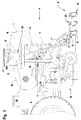
- the agricultural tillage machine shown in the figures comprises in particular a drill (1). It is more precisely a seeder of the type in lines as shown in FIG. 1.
- This seed drill (1) is, in a nonlimiting manner, linked to a device for preparing the seedbed, for example a rotary harrow (10) via a three-point hitch device (3) known to man of career. This combination will prepare the seedbed and sow in one pass.
- the rotary harrow (10) is then placed between the tractor (2) and the seeder (1).
- the seed drill (1) is thus moved in one direction and one direction in advance indicated by the arrow (4) in a field to seed.
- This seed drill (1) can also be directly coupled to a tractor (2).
- This exemplary embodiment is not shown in the figures.
- the drill (1) of Figure 1 comprises a frame (5) which is connected to the apparatus of preparation of the seedbed.
- This frame (5) carries a hopper (6) containing seeds to be sown.
- This hopper (6) comprises at its base a metering device (7) seeds.
- the metering device (7) makes it possible to precisely adjust the quantity of seeds to deposit in the soil.
- the seeds contained in the hopper (6) are transported to implantation members (8) by means of pipes (9).
- Each implantation member (8) is formed by a hollow body in the form of rectangular section tube. Its front and base have a tapered piece (11) so that you can open a small trench in the ground.
- the part upper part of each implantation member (8) has an inlet orifice (12) which is connected to a pipe (9) and through which the seeds arrive.
- the lower part of each implantation member (8) has an outlet orifice (13) through which said seeds are implanted in the soil.
- the implantation member (8) comprises in this embodiment, but in a nonlimiting manner, a control device (14) which provides a substantially constant spacing between seeds emerging from the outlet (13).
- This regulating device (14) is arranged in the body. he has falls (15) inclined one towards its next from the inlet port (12) to the outlet (13). Said falls (15) are arranged advantageously zigzag.
- the seeds which arrive by the pipe (9) slide, under the effect of their own weight, on said falls (15) in order to obtain a regularity of removal of said seeds in the groove in the longitudinal direction, that is to say according to the direction in advance (4), and in depth.
- the regulating device (14) is advantageously interchangeable, which makes it suitable for families of seeds to be sown. Such a regulating device (14) is known to the man of the profession and will not be described in more detail.
- the drill (1) is of the type pneumatic.
- the seed metering device (7) communicates with a supply column (16) which opens into a dispensing head (17) of which leaves the pipes (9) leading to the implantation members (8) of the seeds which are arranged at the back across the width of the machine.
- These bodies (8) are located, in a nonlimiting manner, in three rows and are spaced so that there are fairly regular intervals between the lines on which seeds are deposited.
- the frame (5) of the drill (1) additionally carries a generator (18) which produces a flow of air for conveying the seeds to be sown. This is brought by means of a conduit (19) to the base of the supply column (16). This air flow then causes the seeds from the dosing device (7) to the dispensing head (17) in which it divides into several streams which engage with seeds in the pipes (9).
- Each implantation member (8) additionally comprises, after the inlet orifice (12) and the first chute (15), a separating device (20) for said seeds of the airflow carrying them.
- This separation device (20) is for example a gate (21) through which escapes said flow of air.
- This grid (21) has meshes whose dimensions are smaller than those of the seeds of so that the latter are retained inside the implantation member (8). Said grid (21) is located substantially in the extension of said orifice input (12). Thus the flow of air escapes and the seeds fall into the device regulation (14).
- the drill (1) comprises a device for counting seeds (22).
- the latter is represented schematically with a frame in outline Figure 1.
- This seed counting device (22) is connected here on one of the pipes (9) leading to a corresponding implantation member (8).
- Figures 2 to 5 are diagrammatic representations of various examples of realization of a seed counting device (22) adapted to a seeder specific and connected to different places on the drill.
- This counting device seeds (22) must allow, in a relatively simple way, to obtain the number of seeds sown. It includes, for this purpose, a system for the alignment of seeds (23) and a seed counter (24).
- the alignment device (23) allows to align the seeds one behind the other so that a Standard seed counter (24) can spot and count them.
- the counter seed (24) is therefore disposed downstream of said alignment device (23).
- the device of alignment (23) of seeds to be counted is constituted by a sequence of elements of guiding (25) inclined one towards its next and on which slide the seeds to count to align them.
- two elements of consecutive guidance (25) form between them an angle (alpha) of between 60 ° and 100 °. It varies according to the type of seeds to be sown.
- alpha angle
- To align the seeds we uses at least three consecutive guide elements (25).
- a grouping ramp (26) is arranged upstream the first guide element (25). Its function is to receive seeds that come through the pipe (9) and ensure that they fall at the top of the first guiding element (25).
- This grouping ramp (26) has a section flat transverse.
- the guiding elements (25) have, for their part, advantageously a shape of gutters for guiding seeds.
- the seeds slide so from one guide element (25) towards the other to be aligned at the output of the last guiding element (25).
- Said gutters have a V-shaped profile with a opening angle (beta) between 50 ° and 70 °.
- An opening angle (beta) of 60 ° gives a very good result of guiding seeds. Guiding small seed is improved when the guide members (25) have a section transverse V-shaped with a rounded bottom. It is important that at least last guide element (25) has a gutter shape.
- the various elements of guiding (25) of the seed alignment device (23) are grouped together in a single piece (27) for example in the form of a cassette (28).
- This single piece (27) could be advantageously provided removable and interchangeable, which makes it possible to adapt the seed counting device (22) to seed families to count.
- the cassette (28) shown in FIG. 2 is suitable for sowing large diameter seeds such as wheat or barley.
- the cassette (28) has three guiding elements (25).
- the angle (alpha) between two consecutive guidance elements is variable. Between the first and second guiding elements (25), the angle (alpha) is close to 70 ° whereas the angle (alpha) between the second and last guide elements (25) is substantially equal to 90 °.
- the bottom of the gutter of these guide elements (25) is round.
- the cassette (28) shown in FIG. 3 is rather adapted for seeds small diameter. Note that this cassette (28) has more guide elements (25) in the form of gutters. These elements (25) have a reduced length and occupy only part of the cassette (28). rounding in the bottom of the V-shape is suitable for small diameters of seeds in order to better channel the seeds. The ends of these guide elements (25) are arranged closer together to avoid the rebound of seeds when passing from one to the other.
- the angle (alpha) between two elements of consecutive guidance (25) is here preferably identical for all the elements of guide.
- the counting device of FIG. seed (22) fits on one of the pipes (9). Seeds passing through said pipe (9) enter the cassette (28), slide on the guide elements (25) to be aligned and then counted as output by the seed counter (24). These seeds then continue their way until they reach the ground.
- the device counting of seeds (22) is implanted on the pipe (9) upstream of said organ implantation (8).
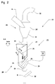
- FIG. 2 schematically represents a first exemplary embodiment of the invention.
- the seed counting device (22) of Figure 2 is adapted for a planter (1) of the pneumatic type as represented in FIG. the combined agricultural machine according to Figure 1 is attached to the tractor (2) which allows to move it on a field and animate it.
- Organs of implantation (8) open small furrows in the earth in which are deposited seeds. These pass from the hopper (6) into the feed column (16) passing through a respective metering member of the metering device (7). In said column (16), they are driven by the flow of air produced by the generator (18). This air flow arrives in the head (17) which ensures a distribution towards the pipes (9). In the latter the seeds are taken to the organs implantation (8).
- the seed counting device (22) is connected to one of these pipes (9).
- the seeds of this pipe (9) therefore first pass through the device alignment of the seeds to count (23) to be counted by the seed counter (24) before continuing their progression in said pipe (9) to the corresponding implant (8) and be deposited in the groove opened by this implantation member (8).
- the airflow separation device (29) is realized by a cyclone (29 ').
- This cyclone (29 ') is located upstream of the alignment device (23).
- the pipe (9) with the seeds conveyed by the air flow opens tangentially in said cyclone (29 '). It has in its upper part a orifice (30) through which the flow of air escapes.
- the cyclone (29 ') is prolonged towards down through a pipe (31) through which the seeds fall by gravity into said alignment device (23). The seeds are counted at the exit via the seed counter (24).
- the seeds are then transported to the implantation member (8) corresponding to be implanted in the earth.
- the seeds to count can be conveyed by a flow of air produced by a separate generator (180).
- the air injection device (32) is directly connected to said generator (180).
- generator (180) producing a flow of air for conveying seeds to count or the seeds already counted can advantageously be constituted directly by the generator (18) producing a flow of air for conveying the seeds to be sown.
- the alignment of the seeds at the cassette outlet (28) is optimal for the counter of seeds (24).
- the latter transmits the number of seeds counted to a terminal (33). He compares the number of seeds that was counted to a number of seeds to sow per square meter for example.
- the terminal (33) also makes it possible to regulate automatically, where appropriate, the dosing device (7) to modify the number of seeds sown.
- the terminal (33) is placed in the tractor cabin (2).
- the seed counter (24) is made for example by a cell photoelectric. It is generally realized by a sensor available in the trade.
- Another solution for reinjecting an air flow into the pipe (9) bringing the seeds in the soil is to use the air flow separated by the separating device (29) to reinject it into the stream of seeds counted downstream of the counter of seeds (24).
- a device for re-injecting the separated air flow is therefore provided in downstream of the seed counter (24).
- the seed counter could very well be functional even if the flow of seeds to be counted is not separated from the air flow, because the flow of air does not does not really disturb the alignment of the seeds, but rather the spacing between two successive seeds which does not really affect counting.
- the counting device of FIG. seeds (22) is provided on one of the pipes (9) of a mechanical seeder.
- the transport of seeds from the hopper (6) to said seed implantation organs (8) is carried out by gravity.
- Such a seed drill therefore has no generator generating a flow of air.
- the pipes (9) are directly connected to a metering member of the metering device (7). Seeds leaving a dosing member fall by gravity on the grouping ramp (26) then slide on the different guide elements (25) so as to be aligned in output of the cassette (28). The seeds are then counted by a meter (24) adequate and continue to slide to the corresponding implantation member (8).
- the seed counting device (22) is arranged so that the pipe (9) opens vertically at the entrance of the cassette (28) so that the seeds fall directly onto the grouping ramp (26).
- the seeds in cassette outlet (28) is recovered by a funnel (34).
- the cassette (28) shown in Figure 3 is adapted to align seeds of small sizes.
- seed counting device (22) is implanted directly upstream of a implantation member (8).
- This third example shows a counting device of seeds (22) adapted for a pneumatic seeder. It includes a device for separating the airflow (20) from the seed stream to be counted. It is realized under the form of a grid (21). The flow of seeds arrives transversely through report to the cassette (28). The seeds fall against the grid (21) which passes the flow of air but retains the seeds that fall under the effect of their own weight in the alignment device (23). They fall on the grouping ramp (26) then slide from one guide element (25) in the next to the exit where they are counted.
- the counted seeds then fall directly on the falls (15) of the regulating device (14) implanted in the implant member (8) corresponding to arrive in the ground. They arrive at intervals constant and at low speed. This prevents them from still rolling on the ground and allows to obtain in a simple way a regular sowing.
- This third embodiment is simple because it does not require reinjection of air in a pipe (9). Moreover, the seed counting device (22) is so placed relatively close to the ground and therefore has a lesser influence on the sowing operation.
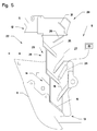
- seed counting device (22) is advantageously placed at least partially in an implantation member (8).
- said elements of guide (25) of the seed alignment device (23) are here less partially constituted by said falls (15) of at least one of said regulating devices (14).
- This fourth example therefore reduces including the added height of the seed counting device (22) and the regulating device (14). It is designed to be mounted on a drill pneumatic.
- the flow of seeds also arrives transversally for evacuate the air flow through the grid (21).
- at least one guide element (25) is added to the drops (15) and a grouping ramp (26). This makes it possible to have the seed counter (24) on the first chute (15), the seeds being already aligned at this stage.
- Another advantage of the implantation of the seed counter in the cassette (28) is the protect from external aggression due mainly to the land that can be projected.
- the drill (1) comprises a "2-way” valve mounted between the supply column (16) and a respective dosage of a dispensing head (17). Said "2-way” valve allowing in a position the conveyance of the seeds leaving said organ of dosing to said feed column (16) and in the other position, the conveying the seeds of said dosing member to the counting device of seeds (22). This valve being controlled by the terminal (33).
- This example of realization therefore only allows to count the seeds before starting the sowing operation and / or during headland maneuvers, as the seeds are either directed to the dispensing head (17) for sowing or to the seed counter (24) to be counted. A continuous check of number of seeds during the sowing operation is therefore not possible but this This procedure can often be sufficient to properly set the dosage (7).
Landscapes
- Life Sciences & Earth Sciences (AREA)
- Soil Sciences (AREA)
- Environmental Sciences (AREA)
- Sowing (AREA)
Applications Claiming Priority (2)
| Application Number | Priority Date | Filing Date | Title |
|---|---|---|---|
| FR0314312 | 2003-12-05 | ||
| FR0314312A FR2863142B1 (fr) | 2003-12-05 | 2003-12-05 | Semoir equipe d'un systeme de comptage de graines |
Publications (2)
| Publication Number | Publication Date |
|---|---|
| EP1537768A1 true EP1537768A1 (de) | 2005-06-08 |
| EP1537768B1 EP1537768B1 (de) | 2013-03-13 |
Family
ID=34451731
Family Applications (1)
| Application Number | Title | Priority Date | Filing Date |
|---|---|---|---|
| EP20040300829 Ceased EP1537768B1 (de) | 2003-12-05 | 2004-12-01 | Sämaschine ausgestattet mit einer Zähleinrichtung |
Country Status (2)
| Country | Link |
|---|---|
| EP (1) | EP1537768B1 (de) |
| FR (1) | FR2863142B1 (de) |
Cited By (8)
| Publication number | Priority date | Publication date | Assignee | Title |
|---|---|---|---|---|
| DE102006038865A1 (de) * | 2006-08-18 | 2008-02-21 | Alois Pöttinger Maschinenfabrik Gmbh | Sämaschine sowie Verfahren zur Regelung des Austrags einer Sämaschine |
| US9699956B2 (en) | 2012-03-22 | 2017-07-11 | Bayer Intellectual Property Gmbh | Dust particles separator for seeding machine |
| US9801330B2 (en) | 2015-11-04 | 2017-10-31 | Cnh Industrial Canada, Ltd. | Meter roller cartridge frame for an agricultural metering system |
| US9844174B2 (en) | 2014-11-04 | 2017-12-19 | Cnh Industrial Canada, Ltd. | Modular meter roller cartridge |
| US9939302B2 (en) | 2014-11-04 | 2018-04-10 | Cnh Industrial Canada, Ltd. | Split meter roller shaft |
| US10455759B2 (en) | 2014-11-04 | 2019-10-29 | Cnh Industrial Canada, Ltd. | Quick release bearing couplers |
| US20240306533A1 (en) * | 2021-07-06 | 2024-09-19 | Väderstad Holding Ab | Agricultural Implement and Method for Feeding Granular Material |
| CN121336576A (zh) * | 2025-12-15 | 2026-01-16 | 湖南德人生物科技有限公司 | 一种高速精量播种设备及其在牧草种植中的应用 |
Citations (7)
| Publication number | Priority date | Publication date | Assignee | Title |
|---|---|---|---|---|
| DE62541C (de) * | J. BERTOLDI in Neubrandenburg i. M | Saatleitungsröhren für Drillmaschinen | ||
| GB2082006A (en) * | 1980-08-08 | 1982-02-24 | Dickey John Corp | Seed planter |
| DE3535871A1 (de) | 1985-10-08 | 1987-04-09 | Andreas Reichhardt | Dosiereinrichtung fuer gekoerntes schuettgut |
| EP0829193A1 (de) * | 1996-09-11 | 1998-03-18 | Universität Hohenheim | Vergleichmässigungseinrichtung für die Dosierung von Granulat, insbesondere zur Verwendung bei einer Drillmaschine (Sämaschine) |
| DE10037713A1 (de) | 2000-08-02 | 2002-02-21 | Lemken Gmbh & Co Kg | Pneumatische Drillmaschine mit Regeleinrichtung |
| DE10134991A1 (de) | 2001-07-18 | 2003-02-06 | Lemken Gmbh & Co Kg | Drillmaschine mit automatischer Kalibrierung |
| EP1341122A1 (de) * | 2002-03-01 | 2003-09-03 | Centre National Du Machinisme Agricole, Du Genie Rural, Des Eaux Et Des Forets (Cemagref) | Vorrichtung zum Zählen von Partikeln, wie z.B. aus einer Sähmaschine abgegebenes Saatgut |
-
2003
- 2003-12-05 FR FR0314312A patent/FR2863142B1/fr not_active Expired - Fee Related
-
2004
- 2004-12-01 EP EP20040300829 patent/EP1537768B1/de not_active Ceased
Patent Citations (7)
| Publication number | Priority date | Publication date | Assignee | Title |
|---|---|---|---|---|
| DE62541C (de) * | J. BERTOLDI in Neubrandenburg i. M | Saatleitungsröhren für Drillmaschinen | ||
| GB2082006A (en) * | 1980-08-08 | 1982-02-24 | Dickey John Corp | Seed planter |
| DE3535871A1 (de) | 1985-10-08 | 1987-04-09 | Andreas Reichhardt | Dosiereinrichtung fuer gekoerntes schuettgut |
| EP0829193A1 (de) * | 1996-09-11 | 1998-03-18 | Universität Hohenheim | Vergleichmässigungseinrichtung für die Dosierung von Granulat, insbesondere zur Verwendung bei einer Drillmaschine (Sämaschine) |
| DE10037713A1 (de) | 2000-08-02 | 2002-02-21 | Lemken Gmbh & Co Kg | Pneumatische Drillmaschine mit Regeleinrichtung |
| DE10134991A1 (de) | 2001-07-18 | 2003-02-06 | Lemken Gmbh & Co Kg | Drillmaschine mit automatischer Kalibrierung |
| EP1341122A1 (de) * | 2002-03-01 | 2003-09-03 | Centre National Du Machinisme Agricole, Du Genie Rural, Des Eaux Et Des Forets (Cemagref) | Vorrichtung zum Zählen von Partikeln, wie z.B. aus einer Sähmaschine abgegebenes Saatgut |
Cited By (9)
| Publication number | Priority date | Publication date | Assignee | Title |
|---|---|---|---|---|
| DE102006038865A1 (de) * | 2006-08-18 | 2008-02-21 | Alois Pöttinger Maschinenfabrik Gmbh | Sämaschine sowie Verfahren zur Regelung des Austrags einer Sämaschine |
| US9699956B2 (en) | 2012-03-22 | 2017-07-11 | Bayer Intellectual Property Gmbh | Dust particles separator for seeding machine |
| US9844174B2 (en) | 2014-11-04 | 2017-12-19 | Cnh Industrial Canada, Ltd. | Modular meter roller cartridge |
| US9939302B2 (en) | 2014-11-04 | 2018-04-10 | Cnh Industrial Canada, Ltd. | Split meter roller shaft |
| US10455759B2 (en) | 2014-11-04 | 2019-10-29 | Cnh Industrial Canada, Ltd. | Quick release bearing couplers |
| US10620028B2 (en) | 2014-11-04 | 2020-04-14 | Cnh Industrial Canada, Ltd. | Split meter roller shaft |
| US9801330B2 (en) | 2015-11-04 | 2017-10-31 | Cnh Industrial Canada, Ltd. | Meter roller cartridge frame for an agricultural metering system |
| US20240306533A1 (en) * | 2021-07-06 | 2024-09-19 | Väderstad Holding Ab | Agricultural Implement and Method for Feeding Granular Material |
| CN121336576A (zh) * | 2025-12-15 | 2026-01-16 | 湖南德人生物科技有限公司 | 一种高速精量播种设备及其在牧草种植中的应用 |
Also Published As
| Publication number | Publication date |
|---|---|
| FR2863142A1 (fr) | 2005-06-10 |
| EP1537768B1 (de) | 2013-03-13 |
| FR2863142B1 (fr) | 2006-03-17 |
Similar Documents
| Publication | Publication Date | Title |
|---|---|---|
| US11849665B2 (en) | Seeding machine with seed delivery system | |
| EP2854499B1 (de) | Einzelkornsämaschine und kornvereinzelungsscheibe mit offenen rillen | |
| EP0598636B1 (de) | Einzelkornsämaschine | |
| EP2931019B1 (de) | Vorrichtung für eine selbstgeregelte pneumatische stromversorgung mit mittel zur regulierung eines luftdurchtrittsabschnitts | |
| EP1537768B1 (de) | Sämaschine ausgestattet mit einer Zähleinrichtung | |
| EP1138186B1 (de) | Sävorrichtung und Sämaschine mit solchen Sävorrichtungen | |
| FR2531603A1 (fr) | Semoir en poquets | |
| EP3238518B1 (de) | Sämaschine, die mit einer vorrichtung zur regulierung der samenverteilung ausgestattet ist, und entsprechende reguliervorrichtung | |
| EP3238519B1 (de) | Reguliervorrichtung der verteilung von samen für sämaschine, und entsprechende sämaschine | |
| EP1430761B1 (de) | Dosiervorrichtung für eine Sämaschine, die mehrere Produkte gleichzeitig verteilen kann | |
| EP3476192B1 (de) | Dosiervorrichtung der verteilung von saatkörnern für eine sämaschine, und entsprechende sämaschine | |
| EP3031312A1 (de) | Verteilungsgehäuse mit druckbeaufschlagtem bereich für einzelkornsämaschine | |
| BR132015013585E2 (pt) | A sowing machine for a ramp unit, and, a method for dispensing a seed of a seeder for a subsoil | |
| BE543355A (de) | ||
| BR132015013582E2 (pt) | Seeder |
Legal Events
| Date | Code | Title | Description |
|---|---|---|---|
| PUAI | Public reference made under article 153(3) epc to a published international application that has entered the european phase |
Free format text: ORIGINAL CODE: 0009012 |
|
| AK | Designated contracting states |
Kind code of ref document: A1 Designated state(s): AT BE BG CH CY CZ DE DK EE ES FI FR GB GR HU IE IS IT LI LT LU MC NL PL PT RO SE SI SK TR |
|
| AX | Request for extension of the european patent |
Extension state: AL BA HR LV MK YU |
|
| 17P | Request for examination filed |
Effective date: 20051129 |
|
| AKX | Designation fees paid |
Designated state(s): DE DK FR IT |
|
| 17Q | First examination report despatched |
Effective date: 20060207 |
|
| GRAP | Despatch of communication of intention to grant a patent |
Free format text: ORIGINAL CODE: EPIDOSNIGR1 |
|
| GRAP | Despatch of communication of intention to grant a patent |
Free format text: ORIGINAL CODE: EPIDOSNIGR1 |
|
| GRAS | Grant fee paid |
Free format text: ORIGINAL CODE: EPIDOSNIGR3 |
|
| GRAA | (expected) grant |
Free format text: ORIGINAL CODE: 0009210 |
|
| AK | Designated contracting states |
Kind code of ref document: B1 Designated state(s): DE DK FR IT |
|
| REG | Reference to a national code |
Ref country code: DE Ref legal event code: R096 Ref document number: 602004041320 Country of ref document: DE Effective date: 20130508 |
|
| PLBE | No opposition filed within time limit |
Free format text: ORIGINAL CODE: 0009261 |
|
| STAA | Information on the status of an ep patent application or granted ep patent |
Free format text: STATUS: NO OPPOSITION FILED WITHIN TIME LIMIT |
|
| PG25 | Lapsed in a contracting state [announced via postgrant information from national office to epo] |
Ref country code: DK Free format text: LAPSE BECAUSE OF FAILURE TO SUBMIT A TRANSLATION OF THE DESCRIPTION OR TO PAY THE FEE WITHIN THE PRESCRIBED TIME-LIMIT Effective date: 20130313 |
|
| 26N | No opposition filed |
Effective date: 20131216 |
|
| PG25 | Lapsed in a contracting state [announced via postgrant information from national office to epo] |
Ref country code: IT Free format text: LAPSE BECAUSE OF FAILURE TO SUBMIT A TRANSLATION OF THE DESCRIPTION OR TO PAY THE FEE WITHIN THE PRESCRIBED TIME-LIMIT Effective date: 20130313 |
|
| REG | Reference to a national code |
Ref country code: DE Ref legal event code: R097 Ref document number: 602004041320 Country of ref document: DE Effective date: 20131216 |
|
| REG | Reference to a national code |
Ref country code: FR Ref legal event code: PLFP Year of fee payment: 12 |
|
| REG | Reference to a national code |
Ref country code: FR Ref legal event code: PLFP Year of fee payment: 13 |
|
| REG | Reference to a national code |
Ref country code: FR Ref legal event code: PLFP Year of fee payment: 14 |
|
| PGFP | Annual fee paid to national office [announced via postgrant information from national office to epo] |
Ref country code: FR Payment date: 20181226 Year of fee payment: 15 |
|
| PGFP | Annual fee paid to national office [announced via postgrant information from national office to epo] |
Ref country code: DE Payment date: 20181231 Year of fee payment: 15 |
|
| REG | Reference to a national code |
Ref country code: DE Ref legal event code: R119 Ref document number: 602004041320 Country of ref document: DE |
|
| PG25 | Lapsed in a contracting state [announced via postgrant information from national office to epo] |
Ref country code: FR Free format text: LAPSE BECAUSE OF NON-PAYMENT OF DUE FEES Effective date: 20191231 Ref country code: DE Free format text: LAPSE BECAUSE OF NON-PAYMENT OF DUE FEES Effective date: 20200701 |