EP1537968A2 - Verfahren und Anlagen zur Beleimung von Fasern und eine Faserbeleimungsvorrichtung - Google Patents
Verfahren und Anlagen zur Beleimung von Fasern und eine Faserbeleimungsvorrichtung Download PDFInfo
- Publication number
- EP1537968A2 EP1537968A2 EP04028589A EP04028589A EP1537968A2 EP 1537968 A2 EP1537968 A2 EP 1537968A2 EP 04028589 A EP04028589 A EP 04028589A EP 04028589 A EP04028589 A EP 04028589A EP 1537968 A2 EP1537968 A2 EP 1537968A2
- Authority
- EP
- European Patent Office
- Prior art keywords
- fibers
- fiber
- gluing
- adhesive
- opening
- Prior art date
- Legal status (The legal status is an assumption and is not a legal conclusion. Google has not performed a legal analysis and makes no representation as to the accuracy of the status listed.)
- Granted
Links
- 239000000835 fiber Substances 0.000 title claims abstract description 122
- 238000004026 adhesive bonding Methods 0.000 title claims description 40
- 238000000034 method Methods 0.000 title claims description 39
- 239000000853 adhesive Substances 0.000 claims abstract description 36
- 230000001070 adhesive effect Effects 0.000 claims abstract description 36
- 239000007921 spray Substances 0.000 claims abstract description 13
- 239000003292 glue Substances 0.000 claims description 29
- 238000003892 spreading Methods 0.000 claims description 11
- 238000009826 distribution Methods 0.000 claims description 5
- 238000001035 drying Methods 0.000 claims description 5
- 238000009434 installation Methods 0.000 claims description 5
- 238000004513 sizing Methods 0.000 claims description 5
- 125000006850 spacer group Chemical group 0.000 claims description 3
- 239000004823 Reactive adhesive Substances 0.000 claims description 2
- 238000000605 extraction Methods 0.000 claims 1
- 238000004519 manufacturing process Methods 0.000 claims 1
- 241000273930 Brevoortia tyrannus Species 0.000 description 13
- 238000005507 spraying Methods 0.000 description 11
- 238000005054 agglomeration Methods 0.000 description 9
- 230000002776 aggregation Effects 0.000 description 9
- WSFSSNUMVMOOMR-UHFFFAOYSA-N Formaldehyde Chemical compound O=C WSFSSNUMVMOOMR-UHFFFAOYSA-N 0.000 description 6
- 230000001174 ascending effect Effects 0.000 description 2
- 238000007796 conventional method Methods 0.000 description 1
- 230000001419 dependent effect Effects 0.000 description 1
- 238000004090 dissolution Methods 0.000 description 1
- 238000005516 engineering process Methods 0.000 description 1
- 239000011094 fiberboard Substances 0.000 description 1
- 238000007731 hot pressing Methods 0.000 description 1
- 230000010354 integration Effects 0.000 description 1
- 239000000463 material Substances 0.000 description 1
- 238000004064 recycling Methods 0.000 description 1
- 238000000926 separation method Methods 0.000 description 1
- 239000004834 spray adhesive Substances 0.000 description 1
- 238000009966 trimming Methods 0.000 description 1
- 238000009827 uniform distribution Methods 0.000 description 1
Images



Classifications
-
- B—PERFORMING OPERATIONS; TRANSPORTING
- B27—WORKING OR PRESERVING WOOD OR SIMILAR MATERIAL; NAILING OR STAPLING MACHINES IN GENERAL
- B27N—MANUFACTURE BY DRY PROCESSES OF ARTICLES, WITH OR WITHOUT ORGANIC BINDING AGENTS, MADE FROM PARTICLES OR FIBRES CONSISTING OF WOOD OR OTHER LIGNOCELLULOSIC OR LIKE ORGANIC MATERIAL
- B27N3/00—Manufacture of substantially flat articles, e.g. boards, from particles or fibres
- B27N3/08—Moulding or pressing
- B27N3/10—Moulding of mats
- B27N3/14—Distributing or orienting the particles or fibres
-
- B—PERFORMING OPERATIONS; TRANSPORTING
- B27—WORKING OR PRESERVING WOOD OR SIMILAR MATERIAL; NAILING OR STAPLING MACHINES IN GENERAL
- B27N—MANUFACTURE BY DRY PROCESSES OF ARTICLES, WITH OR WITHOUT ORGANIC BINDING AGENTS, MADE FROM PARTICLES OR FIBRES CONSISTING OF WOOD OR OTHER LIGNOCELLULOSIC OR LIKE ORGANIC MATERIAL
- B27N1/00—Pretreatment of moulding material
- B27N1/02—Mixing the material with binding agent
- B27N1/0263—Mixing the material with binding agent by spraying the agent on the falling material, e.g. with the material sliding along an inclined surface, using rotating elements or nozzles
Definitions
- the invention relates to a method for gluing fibers after the Preamble of claim 1, a plant for carrying out the Method and a Faserbeleimungsvorraum.
- the fibers are glued in a blowpipe, the connecting tube from the refiner to the dryer, or adhesives using various combinations of dry gluing techniques.
- Fiberboard-coated fibers are dried with a one-stage or two-stage dryer from a starting moisture of 30-110% to a target moisture of 5-15%.
- the glued fibers are placed in an air stream of a tube dryer and transported in about 3 seconds to the separator (cyclone) at a speed of 30-80 m / sec, where they are separated from the dryer air in about 3 seconds and from a rotary valve be removed.
- the separator cyclone
- the fibers are added twice to the hot air stream and separated twice from the hot air with a separator.
- the adhesive saving is about the same size in the industrially carried out pipe and mixer gluing process, since the adhesive saving is essentially due to the avoidance of the pre-hardening due to the high dryer inlet temperature.
- Adhesive insert Blowpipe line 1st stage dryer Adhesive insert Blowpipe line 2nd stage dryer Adhesive insert Mixer or raw gluing of known methods Dryer inlet temperature of the air [° C] 180 (exhaust air dryer) 140 (1st level) 135 (2nd level) 50 fiber temperature before gluing Dew point temperature at the end of the dryer [° C] 46 50 (1st level) MDF standard 10-13 8th 7 (some glue spots) MDF deep tilling quality 12 11 Not possible to disturb glue spots
- DE 16 53 223 A describes a method and a device, can be glued with the falling fibers.
- This method describes the separation of the fibers before spraying, the spraying the fibers in free fall from the side and a resolution of the fibers or of Fiber agglomerations after spraying.
- the fibers should be in front of the Spraying be separated by means of putting in rotation and over a Circular movement to enter the free space.
- This method with device could not prevail because the fiber singulation by means of rotation Within a stirrer tends to blockages, the throughputs too low and especially the lateral spraying to an uneven Gluing leads.
- Fibers are said to be in a cylindrical tower fall with a diameter of 1.5 m and a length of 4 m and at Fall off the side with adhesive droplets to be sprayed.
- there Fiber agglomerates - ie over-gluing - are consciously accepted taken.
- the agglomerates in Refinem or Mills dissolved again.
- no adhesive can be saved, as the Fiber distribution over the cross section of the tower and the glue distribution on The fibers are much too uneven when sprayed from the edge. fibers, which are located in the middle of the tower receive very little glue.
- DE 19 04 856 A from which the invention proceeds, is a device for gluing falling fibers.
- This device provides a gluing, in which the gluing nozzles within the descending fiber are installed and the adhesive in the direction of falling fibers is sprayed - a so-called internal gluing.
- the advantages of an internal spraying of the fiber stream in terms of a better uniformity of the adhesive application are recognized.
- the fibers are transported by means of transport air to a discharge head. In the Discharge heads protrude from the wall sheets to about the middle of the head. In these sheets nozzles are installed, which spray the adhesive down.
- the device described therein does not solve the problem of blockages by fibers that settle over the protruding sheets.
- the invention has for its object to provide a method with which it is possible in the blowpipe glued fibers without precuring the To dry adhesive and a device for carrying out the process to accomplish.
- a plant for carrying out the method comprises a blowpipe and a Pipe stream dryer for pre-gluing, a transfer device for the Fibers into a fiber bunker, a conduit and a housing for transfer the fibers in a Bunkeraustrag and therein the arrangement of a Faserbeleimungsvorraum with discharge head for the entry of glued Includes fibers in a classifier or directly in a scattered bunker.
- the Faserbeleimungsvorraum for the inventive method and the inventive system is characterized by the arrangement of several Opening rollers one above the other on several axes of rotation in the bunker discharge, a conveyor of the fibers by guide plates formed locks in a grid opening, wherein the grid opening through the horizontally arranged ends of the guide plates is formed and wherein each housed at the end of each guide plate several glue nozzles are made.
- the fibers are separated in Bunkeraustrag by opening rollers and fall through guide plates directed to a grid opening down, wherein At the end of the guide sheets glue nozzles are attached, which are in the direction of spraying falling fiber.
- By the method according to the invention is for Time of adhesive application ensured that a uniform Distribution of the fibers over the full spray surface in the discharge head is present and that the fibers enter dissolved in the spray zone of the grid opening.
- the fact that the resolution rollers at much higher speed the fibers from the Bunkeraustrag encourage than the conventional bunkers, is one Part of the fibers conveyed horizontally up to a distance of 2 m. That means that Fibers from upper opening rollers are almost to the opposite Wall transported while the fibers from the lower opening rollers less be transported far.
- the fiber throughput should not exceed 30 t, and preferably 2 - 20 t per hour and per m 2 spray surface, so that the fibers do not form a too dense curtain. This ensures that also the fibers, which are located in the middle between two guide plates, are glued.
- the spray cone of the glue nozzles is adjusted so that only a slight overlap of two adjacent spray cone occurs.
- the guide plate spacing is chosen so that the distance from the glue nozzle to the point in the middle of two guide plates is not so great.
- the operating costs of the device are significantly lower than the conventional mixer or Rohrbeleimungs Kunststoffs Kunststoff as an additional Air transport does not have to be carried out. Likewise, the Investment costs significantly lower than with conventional methods. If the integration into an existing scatter bin is done additional machines necessary. Also, no disturbing Formaldehyde emissions in the exhaust air. Surprisingly, it has become also pointed out that the glue spots as good as no longer exist when some of the adhesive is previously in the blowpipe line on the fibers is applied. In a combined gluing of Blasrohrline and Dry gluing should not be used to further reduce the adhesion of the fibers Temperatures above 110 ° C are dried. This can be a 3- or Multi-stage dryer used to reduce inlet temperatures become.
- the device according to the invention can be used directly as a scattering bin over the Spreading head or over a conveyor belt which leads the fibers to the spreading head, or installed in front of the classifier or in front of the spreading bunker. If the Fibers are not yet spotted and should be dried, the Installation in front of the sifter.
- Agglomerations form after gluing by moving the fibers with each other and in contact with the walls (pipes especially at Transportation in pipelines and warehouses in the bunker (in the bunker only at the Exterior wall).
- the agglomerations are later than glue spots in the plates to see. These agglomerations are particularly intense immediately in the first 2 - 10 seconds after gluing, when glue is applied to the Fibers have not dried yet.
- the gluing is done directly over the spreading head the should Width of the discharge head of the opening of the maximum spreading width correspond.
- the gluing over the scattering head can form fiber agglomerations after gluing as good as no longer form, because the fibers are no longer transported and with the walls except for the Spillway have no contact. The fibers only have contact with the lateral scattering wall, where agglomerations and thus glue spots form could.
- the agglomeration can but minimized: If the fibers fall on a conveyor belt, the Mat height on the conveyor belt to the spreading head as low as possible be set. The feed rate of the conveyor belt is so adjusted so that the fiber height on the belt is less than 300 mm.
- the wall of the conveyor belt and the scattering wall in front of the Scattering be cooled and / or vibrated and / or with a Air jacket can be provided or on the inside of the wall can be a band run with about the transport speed.
- the Discharge rollers are operated in the scattering head at a higher speed, and with a higher number on the same length (6-10 pieces per 1 m length) and a narrower width, so that agglomeration is not more to get through the scattering head on the forming belt. Even if Despite these measures still small agglomerations on the mat edge This is irrelevant for the later plate, since this Matsrand GmbH first removed over the Matsbeanäumung and / or is then trimmed as a plate edge piece.
- the material recycling of the mat edge trimming, the scalper and the mat return can be guided through a separate fiber opening roller and after the fibers are fed onto the conveyor belt. Then can the conveyor belt will be equipped with recoil rollers.
- a mat scales can be integrated, for dosing the adhesive and for controlling the bunker discharge can be used.
- the fibers should be at least approximately 6 m free immediately after gluing and then into a hot air stream (60 - 80 ° C) passed become. During the fall and in the hot air flow finds one Drying of the freshly glued fibers instead, causing the adhesive something dries and thus less sticky and possibly by the adhesive introduced moisture is reduced.
- the Device also only from a discharge head and a belt conveyor exist, the execution as a bunker is not necessary.
- the width across the The conveying direction can correspond to the classifier width, so that the fibers after the Glueing be transported in the classifier.
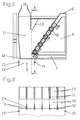
- the plant 1 for carrying out the method is shown in Figure 1 and the Faserbeleimungsvoriques 2 in Figures 2 to 7. It comprises a blower tube 17 and a tube flow dryer 20 for pre-gluing, a transfer device for the fibers in a fiber bunker 3, a line 5 and a housing 6 for transferring the fibers into a Bunkeraustrag 4.
- the Faserbeleimungsvorraum 2 consists of a discharge head 14 for the entry of glued fibers in a classifier 16 or directly on the scattering head 19 in a scattering hopper (not shown) and the arrangement of several opening rollers 8 on top of each other on several axes of rotation in Bunkeraustrag 4.
- the grid opening 9 is formed by horizontally arranged ends of the guide plates 11 and each end of each guide plate 11 more glue nozzles 12 are housed.
- Bunkeraustrag 4 at least three, preferably eight opening rollers 8 are provided for separating the fibers in an oblique arrangement one above the other, wherein the fibers are conveyed from the fiber bunker 3 in the Faserbeleimungsvorraum 2 via a belt weigher 7 continuously.
- the glue nozzles 12 are arranged at the end of the guide plates 11 and optionally provided with widenings 24.
- the guide plates 11 are designed to form locks 10 from the opening rollers 8 to the glue nozzles 12, wherein adjustable baffles 13 are mounted between the sluices 10.
- the air flow can be influenced by the discharge head 14 with an exhaust 18.
- the opening rollers 8 according to Figures 6 and 7 each consist of a torsion bar 25 with it, spaced from spacers 23 slices 21 and therefrom yakradieri protruding release elements 22.
- a hot air supply 15 is provided in the separator 16.
Landscapes
- Life Sciences & Earth Sciences (AREA)
- Engineering & Computer Science (AREA)
- Manufacturing & Machinery (AREA)
- Wood Science & Technology (AREA)
- Forests & Forestry (AREA)
- Application Of Or Painting With Fluid Materials (AREA)
- Dry Formation Of Fiberboard And The Like (AREA)
- Nonwoven Fabrics (AREA)
- Yarns And Mechanical Finishing Of Yarns Or Ropes (AREA)
Abstract
Description
| Klebstoffverbrauch [%] UF und MUF bei verschiedenen Beleimungsmethoden bei gleicher Querzug- und Biegefestigkeit der MDF-Platten. | |||
| Klebstoffeinsatz Blasrohrlinie 1. Stufentrockner | Klebstoffeinsatz Blasrohrlinie 2. Stufentrockner | Klebstoffeinsatz Mischer oder Rohbeleimung bekannter Verfahren | |
| Trocknereintrittstemperatur der Luft [°C] | 180 (Ablufttrockner) | 140 (1. Stufe) 135 (2. Stufe) | 50 Fasertemperatur vor Beleimung |
| Taupunkttemperatur am Ende des Trockners [°C] | 46 | 50 (1. Stufe) | |
| MDF Standard | 10-13 | 8 | 7 (einige Leimflecken) |
| MDF Tieffräsqualität | 12 | 11 | Nicht möglich, Leimflecken stören |
- Figur 1
- eine Anlage zur Durchführung des Verfahrens,
- Figur 2
- die Faserbeleimungsvorrichtung in einem Ausschnitt der Anlage aus Figur 1 in einem größeren Maßstab,
- Figur 3
- einen Schnitt A-A aus Figur 2 in Vorderansicht,
- Figur 4
- einen Ausschnitt aus Figur 3 mit Darstellung der Führungs- und Seitenbleche in Schnitt B-B,
- Figur 5
- eine Draufsicht auf die Faserbeleimungsvorrichtung aus Figur 2,
- Figur 6
- in einer Seitenansicht zwei Auflösungswalzen und
- Figur 7
- eine Draufsicht auf die Auflösungswalzen nach Figur 6.
Die Auflösewalzen 8 bestehen nach den Figuren 6 und 7 jeweils aus einem Drehstab 25 mit darauf angebrachten, von Distanzhülsen 23 beabstandeten Auflösescheiben 21 und daraus zahnradmäßig abstehende Auflöseelemente 22. Zur Nachtrocknung der Fasern nach der Beleimung ist eine Heißluftzufuhr 15 in dem Sichter 16 vorgesehen.
- 1
- Anlage
- 2
- Faserbeleimungsvorrichtung
- 3
- Faserbunker
- 4
- Bunkeraustrag
- 5
- Leitung
- 6
- Gehäuse
- 7
- Bandwaage und Förderband
- 8
- Auflösewalzen
- 9
- Gitteröffnung
- 10
- Schleusen
- 11
- Führungsbleche
- 12
- Leimdüsen
- 13
- Leitblech
- 14
- Austragskopf
- 15
- Heißluftzufuhr
- 16
- Sichter
- 17
- Blasrohr
- 18
- Absaugung
- 19
- Streukopfleitung
- 20
- Rohrstromtrockner
- 21
- Auflösescheiben
- 22
- Auflöseelemente
- 23
- Distanzhülsen
- 24
- Aufweitung
- 25
- Drehstab
Claims (29)
- Verfahren zur Beleimung von Fasern im Trocken- und Halbtrockenverfahren bei der Faserplattenherstellung, bei dem die Fasern aus einem Faserbunker (3) durch einen Bunkeraustrag (4) und innerhalb einer Leitung (5) und Gehäuse (6) zu einem Austragskopf (14) transportiert werden, dadurch gekennzeichnet, dass die Fasern durch von Führungsblechen (11) gebildeten Schleusen (10) und durch eine Gitteröffnung (9) nach unten geleitet werden und wobei an den Enden der Führungsbleche (11) angeordnete Leimdüsen (12) Klebstoffe in Richtung der abfallenden Fasern sprühen.
- Verfahren nach Anspruch 1, dadurch gekennzeichnet, dass die Fasern aus dem Faserbunker (3) über eine Bandwaage (7) zum Bunkeraustrag (4) kontinuierlich gefördert werden, wobei die Fasern durch die 50 mm bis 1000 mm lange und 200 mm bis 4000 mm breite Gitteröffnung (9) nach unten fallen und dabei in dem herab fallenden Luftstrom mit kleinen Klebstofftröpfchen beaufschlagt werden.
- Verfahren nach Anspruch 1 und 2, dadurch gekennzeichnet, dass die Fasern durch mehrere im Bunkeraustrag (4) übereinander angeordnete Auflösewalzen (8) vereinzelt werden.
- Verfahren nach einem der Ansprüche 1 bis 3, dadurch gekennzeichnet, dass die nahe der Gitteröffnung (9) angeordneten Auflösewalzen (8) gegenüber den weiter entfernt angeordneten Auflösewalzen (8) mit langsamerer Drehzahl betrieben werden.
- Verfahren nach einem der Ansprüche 1 bis 4, dadurch gekennzeichnet, dass durch eine unterschiedliche Einstellung der Drehzahl der Auflösewalzen (8) die Verteilung der Fasern durch die Gitteröffnung (9) beinflußt werden.
- Verfahren nach einem der Ansprüche 1 bis 5, dadurch gekennzeichnet, dass die Verteilung der Fasern durch die Gitteröffnung (9) durch ein oder mehrere verstellbare Leitbleche (13) beeinflußt wird.
- Verfahren nach einem der Ansprüche 1 bis 6, dadurch gekennzeichnet, dass der Faserdurchsatz vor oder nach der Beleimung gewogen und nach dem gemessenem Durchsatzwert die Klebstoffdosierung erfolgt.
- Verfahren nach einem der Ansprüche 1 bis 7, dadurch gekennzeichnet, dass der Faserdurchsatz 2 bis 30 t/h, vorzugsweise 10 t/h, je m2 Sprühfläche beträgt.
- Verfahren nach einem der Ansprüche 1 bis 8, dadurch gekennzeichnet, dass die Fasern vor der Trockenbeleimung in einem Blasrohr (17) vorbeleimt und anschließend in einem mehrstufigen Rohstromtrockner mit einer Eintrittstemperaturen unter 110° Celsius getrocknet werden.
- Verfahren nach einem der Ansprüche 1 bis 8, dadurch gekennzeichnet, dass die Fasern unmittelbar nach der Beleimung auf ein mindestens 1,5 m tiefer liegendes Förderband (7) fallen, wobei die Vorschubgeschwindigkeit des Förderbandes (7) so eingestellt wird, dass die Förderhöhe auf dem Band weniger als 300 mm beträgt und die Fasern anschließend in einen Streukopf fallen.
- Verfahren nach einem der Ansprüche 1 bis 9, dadurch gekennzeichnet, dass das Förderband sowie die Streuwand nach der Beleimung gekühlt, vibriert und/oder mit einem Luftmantel versehen oder an der Innenseite ein Band mit etwa der Transportgeschwindigkeit mitläuft.
- Verfahren nach einem der Ansprüche 1 bis 11, dadurch gekennzeichnet, dass die Fasern am Ende des Förderbandes mittels Austragswalzen vereinzelt werden.
- Verfahren nach einem der Ansprüche 1 bis 12, dadurch gekennzeichnet, dass die Fasern nach dem Beleimen unmittelbar in einem etwa gleich breiten Sichter (16) überführt und darin mit Heißluft (15) beheizt werden und durch Luftzufuhr von den Seitenwänden 100 bis 400 mm nach dem Beleimen verwirbelt werden.
- Verfahren nach einem der Ansprüche 1 bis 13, dadurch gekennzeichnet, dass die Fasern nach dem Beleimen in einen Trichter fallen, der mindestens 6 m tiefer als der Austragkopf (14) angeordnet ist, wobei die Trichterwände von einem Heißluftmantel umgeben werden.
- Verfahren nach einem der Ansprüche 1 bis 14,
gekennzeichnet durch eine Einstellung der Leimdüsen (12) derart, dass ihre Sprühkegel nur mit einer leichten Überlappung zweier benachbarten Sprühkegel erfolgt. - Verfahren nach einem der Ansprüche 1 bis 15, dadurch gekennzeichnet, dass die Beleimung der Fasern direkt über dem Streukopf der Streustation zur Bildung der Fasermatte erfolgt.
- Verfahren nach einem der Ansprüche 1 bis 16,
gekennzeichnet durch die Verwendung eines hochreaktiven Klebstoffes für das Beleimen der Fasern. - Anlage zur Durchführung des Verfahrens nach den Ansprüchen 1 bis 17, umfassend eine Blasrohr (17) und einen Rohrstromtrockner (20) zur Vorbeleimung, eine Überführungsvorrichtung für die Fasern in einen Faserbunker (3), einer Leitung (5) und einem Gehäuse (6) zur Überführung der Fasern in einen Bunkeraustrag (4) und darin die Anordnung einer Faserbeleimungsvorrichtung (2) mit Austragkopf (14) für das Eintragen der beleimten Fasern in einen Sichter (16) oder direkt in einen Streukopfbunker.
- Faserbeleimungsvorrichtung nach Anspruch 18,
gekennzeichnet durch die Anordnung von mehreren Auflösewalzen (8) übereinander auf mehreren Drehachsen im Bunkeraustrag (4), einer Beförderungseinrichtung der Fasern durch von Führungsblechen (11) gebildete Schleusen (10) in eine Gitteröffnung (9), wobei die Gitteröffnung (9) durch die waagrecht angeordnete Enden der Führungsbleche (11) gebildet ist und wobei jeweils am Ende jeden Führungsbleches (11) mehrere Leimdüsen (12) untergebracht sind. - Faserbeleimungsvorrichtung nach Anspruch 19, dadurch gekennzeichnet, dass mindestens drei, vorzugsweise acht Auflösewalzen (8) in schräger Anordnung übereinander vorgesehen sind und ihre Drehzahl 400 bis 1000 Umdrehungen pro Minute beträgt.
- Faserbeleimungsvorrichtung nach einem der Ansprüche 19 und 20, dadurch gekennzeichnet, dass die Fasern aus dem Faserbunker (3) in die Faserbeleimungsvorrichtung (2) über eine Bandwaage (7) kontinuierlich förderbar sind.
- Faserbeleimungsvorrichtung nach einem der Ansprüche 19 bis 21, dadurch gekennzeichnet, dass die Leimdüsen (12) am Ende der Führungsbleche (11) und innerhalb des herabfallenden Faser-/Luftstromes angeordnet sind.
- Faserbeleimungsvorrichtung nach einem der Ansprüche 18 bis 22, dadurch gekennzeichnet, dass die Anordnung der Führungsbleche (11) unter Bildung der Schleusen (10) von den Auflösewalzen (8) bis zu den Leimdüsen (12) ausgeführt ist.
- Faserbeleimungsvorrichtung nach einem der Ansprüche 18 bis 23, dadurch gekennzeichnet, dass der Luftstrom durch den Austragkopf (14) mit einer Absaugung (18) beeinflussbar ist.
- Faserbeleimungsvorrichtung nach einem der Ansprüche 18 bis 24, dadurch gekennzeichnet, dass die Führungsbleche (11) in einer Dicke von 15 mm bis 35 mm von der Auflösewalzen (8) bis zu den Leimdüsen (12) reichend ausgeführt sind.
- Faserbeleimungsvorrichtung nach einem der Ansprüche 18 bis 25, dadurch gekennzeichnet, dass die Auflösebleche in einer Dicke von 2 mm bis 10 mm ausgeführt sind und am Ende für die Leimdüsen durch eine Aufweitung (24) aufgeweitet sind.
- Faserbeleimungsvorrichtung nach einem der Ansprüche 18 bis 26, dadurch gekennzeichnet, dass eine Auflösewalze (8) aus einem Drehstab (25) mit darauf angebrachten, von Distanzhülsen (23) beabstandeten Auflösescheiben (21) und daraus zahnradmäßig abstehende Auflöseelemente (22) besteht.
- Anlage nach Anspruch 18, dadurch gekennzeichnet, dass die Faserbeleimungsvorrichtung (2) direkt über dem Streukopfbunker und dem Fasermattenformband angeordnet ist.
- Anlage nach den Ansprüchen 18 und 27, dadurch gekennzeichnet, dass die Breite der Gitteröffnung (9) der maximalen Fasermattenbreite entspricht.
Priority Applications (1)
| Application Number | Priority Date | Filing Date | Title |
|---|---|---|---|
| SI200431735T SI1537968T1 (sl) | 2003-12-02 | 2004-12-02 | Postopek in sistem za lepljenje vlaken in naprava za lepljenje vlaken |
Applications Claiming Priority (2)
| Application Number | Priority Date | Filing Date | Title |
|---|---|---|---|
| DE10356775A DE10356775A1 (de) | 2003-12-02 | 2003-12-02 | Verfahren und Anlage zur Beleimung von Fasern und eine Faserbeleimungsvorrichtung |
| DE10356775 | 2003-12-02 |
Publications (3)
| Publication Number | Publication Date |
|---|---|
| EP1537968A2 true EP1537968A2 (de) | 2005-06-08 |
| EP1537968A3 EP1537968A3 (de) | 2005-11-23 |
| EP1537968B1 EP1537968B1 (de) | 2011-06-08 |
Family
ID=34442448
Family Applications (1)
| Application Number | Title | Priority Date | Filing Date |
|---|---|---|---|
| EP04028589A Expired - Lifetime EP1537968B1 (de) | 2003-12-02 | 2004-12-02 | Verfahren und Anlagen zur Beleimung von Fasern und eine Faserbeleimungsvorrichtung |
Country Status (4)
| Country | Link |
|---|---|
| EP (1) | EP1537968B1 (de) |
| AT (1) | ATE511967T1 (de) |
| DE (1) | DE10356775A1 (de) |
| SI (1) | SI1537968T1 (de) |
Cited By (1)
| Publication number | Priority date | Publication date | Assignee | Title |
|---|---|---|---|---|
| WO2008071258A1 (de) * | 2006-12-13 | 2008-06-19 | Siempelkamp Maschinen- Und Anlagenbau Gmbh & Co. Kg | Anlage zum beleimen von fasern für die herstellung von faserplatten, insbesondere mdf-platten oder dergleichen holzwerkstoffplatten |
Families Citing this family (2)
| Publication number | Priority date | Publication date | Assignee | Title |
|---|---|---|---|---|
| DE202008015419U1 (de) | 2008-11-21 | 2010-04-22 | Epple, Albrecht, Dr. | Vorrichtung zur Beleimung von Fasern in einem Blasrohr |
| RU2622736C1 (ru) * | 2016-07-19 | 2017-06-19 | Федеральное государственное бюджетное образовательное учреждение высшего образования "Поволжский государственный технологический университет" | Устройство для получения арболита |
Citations (2)
| Publication number | Priority date | Publication date | Assignee | Title |
|---|---|---|---|---|
| DE1653223A1 (de) | 1966-04-23 | 1970-09-17 | Himmelheber Dipl Ing Max | Verfahren und Anlage zur Durchfuehrung der Benetzungsstufe bei der Verarbeitung von Fasermaterial |
| DE19740676A1 (de) | 1997-09-16 | 1999-03-18 | Fraunhofer Ges Forschung | Verfahren zum Beleimen von Fasern |
Family Cites Families (8)
| Publication number | Priority date | Publication date | Assignee | Title |
|---|---|---|---|---|
| DD78881A (de) * | ||||
| US3622077A (en) * | 1968-02-01 | 1971-11-23 | Conwed Corp | Apparatus for air-laying wet fibers |
| US3494992A (en) * | 1968-02-01 | 1970-02-10 | Conwed Corp | Method of producing a mat from an air suspension of fibers and liquid |
| DE4122842C2 (de) * | 1991-07-10 | 1993-11-18 | Glunz Ag | Verfahren zur Herstellung von Faserplatten aus stückigen Holzpartikeln und Isocyanat als Bindemittel |
| DE10018218A1 (de) * | 1999-04-12 | 2001-10-25 | Dieffenbacher Schenck Panel | Formstation |
| DE10020881A1 (de) * | 2000-04-28 | 2001-10-31 | Dieffenbacher Schenck Panel | Vorrichtung zum Streuen von Streugut auf eine kontinuierlich bewegte Unterlage |
| NL1017528C2 (nl) * | 2001-03-07 | 2002-02-26 | Oldenhuis Exp | Inrichting voor het behandelen van landbouwproducten, in het bijzonder aardappelen. |
| DE10226820B3 (de) * | 2002-06-15 | 2004-04-01 | Flakeboard Company Limited, St.Stephen | Verfahren und Vorrichtung zum Beleimen von zur Herstellung von Faserplatten vorgesehenen, getrockneten Fasern |
-
2003
- 2003-12-02 DE DE10356775A patent/DE10356775A1/de not_active Withdrawn
-
2004
- 2004-12-02 SI SI200431735T patent/SI1537968T1/sl unknown
- 2004-12-02 AT AT04028589T patent/ATE511967T1/de active
- 2004-12-02 EP EP04028589A patent/EP1537968B1/de not_active Expired - Lifetime
Patent Citations (2)
| Publication number | Priority date | Publication date | Assignee | Title |
|---|---|---|---|---|
| DE1653223A1 (de) | 1966-04-23 | 1970-09-17 | Himmelheber Dipl Ing Max | Verfahren und Anlage zur Durchfuehrung der Benetzungsstufe bei der Verarbeitung von Fasermaterial |
| DE19740676A1 (de) | 1997-09-16 | 1999-03-18 | Fraunhofer Ges Forschung | Verfahren zum Beleimen von Fasern |
Cited By (2)
| Publication number | Priority date | Publication date | Assignee | Title |
|---|---|---|---|---|
| WO2008071258A1 (de) * | 2006-12-13 | 2008-06-19 | Siempelkamp Maschinen- Und Anlagenbau Gmbh & Co. Kg | Anlage zum beleimen von fasern für die herstellung von faserplatten, insbesondere mdf-platten oder dergleichen holzwerkstoffplatten |
| US7987884B2 (en) | 2006-12-13 | 2011-08-02 | Siempelkamp Maschinen -Und Anlagen Bau GmbH + Co. KG | Installation for applying glue to fibers for the production of fiberboard |
Also Published As
| Publication number | Publication date |
|---|---|
| DE10356775A1 (de) | 2005-07-07 |
| EP1537968B1 (de) | 2011-06-08 |
| SI1537968T1 (sl) | 2011-10-28 |
| EP1537968A3 (de) | 2005-11-23 |
| ATE511967T1 (de) | 2011-06-15 |
Similar Documents
| Publication | Publication Date | Title |
|---|---|---|
| DE10247412C5 (de) | Anlage zum Beleimen von Fasern für die Herstellung von Faserplatten, insbesondere MDF-Platten und dergleichen Holzwerkstoffplatten | |
| DE10153593B4 (de) | Vorrichtung und Verfahren zum Benetzen von Holzfasern mit einem Bindemittelfluid | |
| DE102007049947A1 (de) | Verfahren, Streukopf und Anlage zur Herstellung einer Streugutmatte aus orientiert gestreuten Spanschichten im Zuge der Herstellung von Holzwerkstoffplatten | |
| EP2030748B1 (de) | Streumaschine zur Bildung einer Pressgutmatte oder einer Schicht derselben im Zuger der Herstellung von Holzwerkstoffplatten und ein Verfahren zum Betreiben einer Streumaschine | |
| EP2747966B1 (de) | Verfahren und vorrichtung zur beleimung von partikeln, die aus zur herstellung von werkstoffplatten geeigneten fasern und/oder spänen bestehen | |
| DE69920155T2 (de) | Klebevorrichtung für Holzfaserplattenherstellungsanlagen | |
| DE10247413B4 (de) | Anlage zum Beleimen von Fasern für die Herstellung von Faserplatten, insbesondere MDF-Platten oder dergleichen Holzwerkstoffplatten | |
| EP2476526B1 (de) | Verfahren und Vorrichtung für die Herstellung einer aus Fasern oder Spänen gefertiger platte | |
| DE10247414B4 (de) | Anlage zum Beleimen von Fasern für die Herstellung von Faserplatten, insbesondere MDF-Platten o. dgl. Holzwerkstoffplatten | |
| DE102004033777A1 (de) | Verfahren, Vorrichtung und Streukopf zur Streuung oder Schüttung von Partikeln | |
| DE102009042361B4 (de) | Verfahren zur Herstellung von kartonähnlichen Faserplatten aus Holzfasern | |
| EP1236552B1 (de) | Verfahren und Anlage zur Herstellung von Holzwerkstoffplatten | |
| WO2011082797A1 (de) | Verfahren und streukopf zur herstellung einer streugutmatte aus zumindest einer orientiert gestreuten schicht im zuge der herstellung von holzwerkstoffplatten | |
| DE10226820B3 (de) | Verfahren und Vorrichtung zum Beleimen von zur Herstellung von Faserplatten vorgesehenen, getrockneten Fasern | |
| DE102004001527B4 (de) | Anlage und Verfahren zum Beleimen von Fasern für die Herstellung von Faserplatten, insbesondere MDF-Platten u. dgl. Holzwerkstoffplatten | |
| EP1537968B1 (de) | Verfahren und Anlagen zur Beleimung von Fasern und eine Faserbeleimungsvorrichtung | |
| CH664787A5 (de) | Bauplatte sowie verfahren zu ihrer herstellung und vorrichtung zur durchfuehrung des verfahrens. | |
| EP1442855B1 (de) | Vorrichtung zum Streuen von Streugut auf eine kontinuierlich bewegte Unterlage | |
| DE2023659A1 (en) | Dried raw material treatment to impregnate with a sprayable binder | |
| DE19916448A1 (de) | Streustation für Faserplatten | |
| DE102006062396A1 (de) | Verfahren und Formstation zur Bildung einer Streugutmatte im Zuge der Herstellung von Werkstoffplatten | |
| EP1810805B1 (de) | Verfahren und Formstation zur Bildung einer Streugutmatte im Zuge der Herstellung von Werkstoffplatten | |
| EP1851022B1 (de) | Verfahren und vorrichtung zum herstellen von dämmstoffplatten | |
| EP1747865B1 (de) | Verfahren und Vorrichtung zur Herstellung von Holzwerkstoffplatten | |
| DE102006027540B4 (de) | Verfahren und Vorrichtung zur Herstellung von Formkörpern, insbesondere von Platten, aus Lignocellulose haltigen Fasern |
Legal Events
| Date | Code | Title | Description |
|---|---|---|---|
| PUAI | Public reference made under article 153(3) epc to a published international application that has entered the european phase |
Free format text: ORIGINAL CODE: 0009012 |
|
| AK | Designated contracting states |
Kind code of ref document: A2 Designated state(s): AT BE BG CH CY CZ DE DK EE ES FI FR GB GR HU IE IS IT LI LT LU MC NL PL PT RO SE SI SK TR |
|
| AX | Request for extension of the european patent |
Extension state: AL BA HR LV MK YU |
|
| PUAL | Search report despatched |
Free format text: ORIGINAL CODE: 0009013 |
|
| AK | Designated contracting states |
Kind code of ref document: A3 Designated state(s): AT BE BG CH CY CZ DE DK EE ES FI FR GB GR HU IE IS IT LI LT LU MC NL PL PT RO SE SI SK TR |
|
| AX | Request for extension of the european patent |
Extension state: AL BA HR LV MK YU |
|
| 17P | Request for examination filed |
Effective date: 20060523 |
|
| AKX | Designation fees paid |
Designated state(s): AT BE BG CH CY CZ DE DK EE ES FI FR GB GR HU IE IS IT LI LT LU MC NL PL PT RO SE SI SK TR |
|
| 17Q | First examination report despatched |
Effective date: 20090918 |
|
| GRAP | Despatch of communication of intention to grant a patent |
Free format text: ORIGINAL CODE: EPIDOSNIGR1 |
|
| GRAS | Grant fee paid |
Free format text: ORIGINAL CODE: EPIDOSNIGR3 |
|
| GRAA | (expected) grant |
Free format text: ORIGINAL CODE: 0009210 |
|
| AK | Designated contracting states |
Kind code of ref document: B1 Designated state(s): AT BE BG CH CY CZ DE DK EE ES FI FR GB GR HU IE IS IT LI LT LU MC NL PL PT RO SE SI SK TR |
|
| REG | Reference to a national code |
Ref country code: GB Ref legal event code: FG4D Free format text: NOT ENGLISH |
|
| REG | Reference to a national code |
Ref country code: CH Ref legal event code: EP |
|
| REG | Reference to a national code |
Ref country code: IE Ref legal event code: FG4D Free format text: LANGUAGE OF EP DOCUMENT: GERMAN |
|
| REG | Reference to a national code |
Ref country code: DE Ref legal event code: R096 Ref document number: 502004012574 Country of ref document: DE Effective date: 20110721 |
|
| REG | Reference to a national code |
Ref country code: CH Ref legal event code: PUE Owner name: DIEFFENBACHER GMBH MASCHINEN- UND ANLAGENBAU Free format text: DIEFFENBACHER GMBH + CO. KG#HEILBRONNERSTRASSE 20#75031 EPPINGEN (DE) -TRANSFER TO- DIEFFENBACHER GMBH MASCHINEN- UND ANLAGENBAU#HEILBRONNER STRASSE 20#75031 EPPINGEN (DE) Ref country code: CH Ref legal event code: NV Representative=s name: ISLER & PEDRAZZINI AG |
|
| REG | Reference to a national code |
Ref country code: NL Ref legal event code: VDEP Effective date: 20110608 |
|
| RAP2 | Party data changed (patent owner data changed or rights of a patent transferred) |
Owner name: DIEFFENBACHER GMBH MASCHINEN- UND ANLAGENBAU |
|
| PG25 | Lapsed in a contracting state [announced via postgrant information from national office to epo] |
Ref country code: SE Free format text: LAPSE BECAUSE OF FAILURE TO SUBMIT A TRANSLATION OF THE DESCRIPTION OR TO PAY THE FEE WITHIN THE PRESCRIBED TIME-LIMIT Effective date: 20110608 Ref country code: LT Free format text: LAPSE BECAUSE OF FAILURE TO SUBMIT A TRANSLATION OF THE DESCRIPTION OR TO PAY THE FEE WITHIN THE PRESCRIBED TIME-LIMIT Effective date: 20110608 |
|
| PG25 | Lapsed in a contracting state [announced via postgrant information from national office to epo] |
Ref country code: GR Free format text: LAPSE BECAUSE OF FAILURE TO SUBMIT A TRANSLATION OF THE DESCRIPTION OR TO PAY THE FEE WITHIN THE PRESCRIBED TIME-LIMIT Effective date: 20110909 Ref country code: ES Free format text: LAPSE BECAUSE OF FAILURE TO SUBMIT A TRANSLATION OF THE DESCRIPTION OR TO PAY THE FEE WITHIN THE PRESCRIBED TIME-LIMIT Effective date: 20110919 Ref country code: FI Free format text: LAPSE BECAUSE OF FAILURE TO SUBMIT A TRANSLATION OF THE DESCRIPTION OR TO PAY THE FEE WITHIN THE PRESCRIBED TIME-LIMIT Effective date: 20110608 Ref country code: CY Free format text: LAPSE BECAUSE OF FAILURE TO SUBMIT A TRANSLATION OF THE DESCRIPTION OR TO PAY THE FEE WITHIN THE PRESCRIBED TIME-LIMIT Effective date: 20110608 |
|
| REG | Reference to a national code |
Ref country code: GB Ref legal event code: 732E Free format text: REGISTERED BETWEEN 20111201 AND 20111207 |
|
| PG25 | Lapsed in a contracting state [announced via postgrant information from national office to epo] |
Ref country code: NL Free format text: LAPSE BECAUSE OF FAILURE TO SUBMIT A TRANSLATION OF THE DESCRIPTION OR TO PAY THE FEE WITHIN THE PRESCRIBED TIME-LIMIT Effective date: 20110608 |
|
| REG | Reference to a national code |
Ref country code: SK Ref legal event code: T3 Ref document number: E 10314 Country of ref document: SK Ref country code: IE Ref legal event code: FD4D |
|
| PG25 | Lapsed in a contracting state [announced via postgrant information from national office to epo] |
Ref country code: IS Free format text: LAPSE BECAUSE OF FAILURE TO SUBMIT A TRANSLATION OF THE DESCRIPTION OR TO PAY THE FEE WITHIN THE PRESCRIBED TIME-LIMIT Effective date: 20111008 Ref country code: PT Free format text: LAPSE BECAUSE OF FAILURE TO SUBMIT A TRANSLATION OF THE DESCRIPTION OR TO PAY THE FEE WITHIN THE PRESCRIBED TIME-LIMIT Effective date: 20111010 Ref country code: EE Free format text: LAPSE BECAUSE OF FAILURE TO SUBMIT A TRANSLATION OF THE DESCRIPTION OR TO PAY THE FEE WITHIN THE PRESCRIBED TIME-LIMIT Effective date: 20110608 Ref country code: IE Free format text: LAPSE BECAUSE OF FAILURE TO SUBMIT A TRANSLATION OF THE DESCRIPTION OR TO PAY THE FEE WITHIN THE PRESCRIBED TIME-LIMIT Effective date: 20110608 |
|
| PG25 | Lapsed in a contracting state [announced via postgrant information from national office to epo] |
Ref country code: RO Free format text: LAPSE BECAUSE OF FAILURE TO SUBMIT A TRANSLATION OF THE DESCRIPTION OR TO PAY THE FEE WITHIN THE PRESCRIBED TIME-LIMIT Effective date: 20110608 Ref country code: PL Free format text: LAPSE BECAUSE OF FAILURE TO SUBMIT A TRANSLATION OF THE DESCRIPTION OR TO PAY THE FEE WITHIN THE PRESCRIBED TIME-LIMIT Effective date: 20110608 |
|
| PLBE | No opposition filed within time limit |
Free format text: ORIGINAL CODE: 0009261 |
|
| STAA | Information on the status of an ep patent application or granted ep patent |
Free format text: STATUS: NO OPPOSITION FILED WITHIN TIME LIMIT |
|
| 26N | No opposition filed |
Effective date: 20120309 |
|
| PG25 | Lapsed in a contracting state [announced via postgrant information from national office to epo] |
Ref country code: DK Free format text: LAPSE BECAUSE OF FAILURE TO SUBMIT A TRANSLATION OF THE DESCRIPTION OR TO PAY THE FEE WITHIN THE PRESCRIBED TIME-LIMIT Effective date: 20110608 |
|
| BERE | Be: lapsed |
Owner name: DIEFFENBACHER G.M.B.H. + CO. KG Effective date: 20111231 |
|
| REG | Reference to a national code |
Ref country code: DE Ref legal event code: R097 Ref document number: 502004012574 Country of ref document: DE Effective date: 20120309 |
|
| PG25 | Lapsed in a contracting state [announced via postgrant information from national office to epo] |
Ref country code: MC Free format text: LAPSE BECAUSE OF NON-PAYMENT OF DUE FEES Effective date: 20111231 |
|
| PG25 | Lapsed in a contracting state [announced via postgrant information from national office to epo] |
Ref country code: BE Free format text: LAPSE BECAUSE OF NON-PAYMENT OF DUE FEES Effective date: 20111231 |
|
| REG | Reference to a national code |
Ref country code: DE Ref legal event code: R082 Ref document number: 502004012574 Country of ref document: DE Representative=s name: ANTON HARTDEGEN, DE |
|
| PGFP | Annual fee paid to national office [announced via postgrant information from national office to epo] |
Ref country code: FR Payment date: 20120927 Year of fee payment: 9 |
|
| REG | Reference to a national code |
Ref country code: DE Ref legal event code: R082 Ref document number: 502004012574 Country of ref document: DE Representative=s name: HARTDEGEN, ANTON, DIPL.-ING.(FH), DE Effective date: 20121116 Ref country code: DE Ref legal event code: R081 Ref document number: 502004012574 Country of ref document: DE Owner name: DIEFFENBACHER GMBH MASCHINEN- UND ANLAGENBAU, DE Free format text: FORMER OWNER: DIEFFENBACHER GMBH + CO. KG, 75031 EPPINGEN, DE Effective date: 20121116 |
|
| PGFP | Annual fee paid to national office [announced via postgrant information from national office to epo] |
Ref country code: CH Payment date: 20121220 Year of fee payment: 9 Ref country code: CZ Payment date: 20121108 Year of fee payment: 9 |
|
| PGFP | Annual fee paid to national office [announced via postgrant information from national office to epo] |
Ref country code: SI Payment date: 20121129 Year of fee payment: 9 Ref country code: GB Payment date: 20121218 Year of fee payment: 9 Ref country code: IT Payment date: 20121220 Year of fee payment: 9 Ref country code: SK Payment date: 20121107 Year of fee payment: 9 |
|
| PGFP | Annual fee paid to national office [announced via postgrant information from national office to epo] |
Ref country code: AT Payment date: 20121227 Year of fee payment: 9 |
|
| PGFP | Annual fee paid to national office [announced via postgrant information from national office to epo] |
Ref country code: DE Payment date: 20121231 Year of fee payment: 9 |
|
| PG25 | Lapsed in a contracting state [announced via postgrant information from national office to epo] |
Ref country code: LU Free format text: LAPSE BECAUSE OF NON-PAYMENT OF DUE FEES Effective date: 20111202 |
|
| PG25 | Lapsed in a contracting state [announced via postgrant information from national office to epo] |
Ref country code: BG Free format text: LAPSE BECAUSE OF FAILURE TO SUBMIT A TRANSLATION OF THE DESCRIPTION OR TO PAY THE FEE WITHIN THE PRESCRIBED TIME-LIMIT Effective date: 20110908 |
|
| PG25 | Lapsed in a contracting state [announced via postgrant information from national office to epo] |
Ref country code: TR Free format text: LAPSE BECAUSE OF FAILURE TO SUBMIT A TRANSLATION OF THE DESCRIPTION OR TO PAY THE FEE WITHIN THE PRESCRIBED TIME-LIMIT Effective date: 20110608 |
|
| PG25 | Lapsed in a contracting state [announced via postgrant information from national office to epo] |
Ref country code: HU Free format text: LAPSE BECAUSE OF FAILURE TO SUBMIT A TRANSLATION OF THE DESCRIPTION OR TO PAY THE FEE WITHIN THE PRESCRIBED TIME-LIMIT Effective date: 20110608 |
|
| REG | Reference to a national code |
Ref country code: DE Ref legal event code: R119 Ref document number: 502004012574 Country of ref document: DE |
|
| REG | Reference to a national code |
Ref country code: CH Ref legal event code: PL |
|
| REG | Reference to a national code |
Ref country code: AT Ref legal event code: MM01 Ref document number: 511967 Country of ref document: AT Kind code of ref document: T Effective date: 20131202 |
|
| GBPC | Gb: european patent ceased through non-payment of renewal fee |
Effective date: 20131202 |
|
| PG25 | Lapsed in a contracting state [announced via postgrant information from national office to epo] |
Ref country code: CZ Free format text: LAPSE BECAUSE OF NON-PAYMENT OF DUE FEES Effective date: 20131202 Ref country code: SI Free format text: LAPSE BECAUSE OF NON-PAYMENT OF DUE FEES Effective date: 20131203 |
|
| REG | Reference to a national code |
Ref country code: SI Ref legal event code: KO00 Effective date: 20140728 |
|
| REG | Reference to a national code |
Ref country code: SK Ref legal event code: MM4A Ref document number: E 10314 Country of ref document: SK Effective date: 20131202 |
|
| REG | Reference to a national code |
Ref country code: FR Ref legal event code: ST Effective date: 20140829 |
|
| REG | Reference to a national code |
Ref country code: DE Ref legal event code: R119 Ref document number: 502004012574 Country of ref document: DE Effective date: 20140701 |
|
| PG25 | Lapsed in a contracting state [announced via postgrant information from national office to epo] |
Ref country code: LI Free format text: LAPSE BECAUSE OF NON-PAYMENT OF DUE FEES Effective date: 20131231 Ref country code: DE Free format text: LAPSE BECAUSE OF NON-PAYMENT OF DUE FEES Effective date: 20140701 Ref country code: CH Free format text: LAPSE BECAUSE OF NON-PAYMENT OF DUE FEES Effective date: 20131231 |
|
| PG25 | Lapsed in a contracting state [announced via postgrant information from national office to epo] |
Ref country code: AT Free format text: LAPSE BECAUSE OF NON-PAYMENT OF DUE FEES Effective date: 20131202 Ref country code: SK Free format text: LAPSE BECAUSE OF NON-PAYMENT OF DUE FEES Effective date: 20131202 Ref country code: GB Free format text: LAPSE BECAUSE OF NON-PAYMENT OF DUE FEES Effective date: 20131202 Ref country code: FR Free format text: LAPSE BECAUSE OF NON-PAYMENT OF DUE FEES Effective date: 20131231 |
|
| PG25 | Lapsed in a contracting state [announced via postgrant information from national office to epo] |
Ref country code: IT Free format text: LAPSE BECAUSE OF NON-PAYMENT OF DUE FEES Effective date: 20131231 |
|
| PG25 | Lapsed in a contracting state [announced via postgrant information from national office to epo] |
Ref country code: IT Free format text: LAPSE BECAUSE OF NON-PAYMENT OF DUE FEES Effective date: 20131202 |