EP1538236A2 - Substratträger - Google Patents
Substratträger Download PDFInfo
- Publication number
- EP1538236A2 EP1538236A2 EP04027863A EP04027863A EP1538236A2 EP 1538236 A2 EP1538236 A2 EP 1538236A2 EP 04027863 A EP04027863 A EP 04027863A EP 04027863 A EP04027863 A EP 04027863A EP 1538236 A2 EP1538236 A2 EP 1538236A2
- Authority
- EP
- European Patent Office
- Prior art keywords
- substrate carrier
- substrate
- roller
- projection
- gripping
- Prior art date
- Legal status (The legal status is an assumption and is not a legal conclusion. Google has not performed a legal analysis and makes no representation as to the accuracy of the status listed.)
- Granted
Links
Images


Classifications
-
- H—ELECTRICITY
- H10—SEMICONDUCTOR DEVICES; ELECTRIC SOLID-STATE DEVICES NOT OTHERWISE PROVIDED FOR
- H10P—GENERIC PROCESSES OR APPARATUS FOR THE MANUFACTURE OR TREATMENT OF DEVICES COVERED BY CLASS H10
- H10P72/00—Handling or holding of wafers, substrates or devices during manufacture or treatment thereof
- H10P72/70—Handling or holding of wafers, substrates or devices during manufacture or treatment thereof for supporting or gripping
- H10P72/76—Handling or holding of wafers, substrates or devices during manufacture or treatment thereof for supporting or gripping using mechanical means, e.g. clamps or pinches
- H10P72/7604—Handling or holding of wafers, substrates or devices during manufacture or treatment thereof for supporting or gripping using mechanical means, e.g. clamps or pinches the wafers being placed on a susceptor, stage or support
- H10P72/7608—Handling or holding of wafers, substrates or devices during manufacture or treatment thereof for supporting or gripping using mechanical means, e.g. clamps or pinches the wafers being placed on a susceptor, stage or support characterised by a plurality of separate clamping members, e.g. clamping fingers
-
- C—CHEMISTRY; METALLURGY
- C23—COATING METALLIC MATERIAL; COATING MATERIAL WITH METALLIC MATERIAL; CHEMICAL SURFACE TREATMENT; DIFFUSION TREATMENT OF METALLIC MATERIAL; COATING BY VACUUM EVAPORATION, BY SPUTTERING, BY ION IMPLANTATION OR BY CHEMICAL VAPOUR DEPOSITION, IN GENERAL; INHIBITING CORROSION OF METALLIC MATERIAL OR INCRUSTATION IN GENERAL
- C23C—COATING METALLIC MATERIAL; COATING MATERIAL WITH METALLIC MATERIAL; SURFACE TREATMENT OF METALLIC MATERIAL BY DIFFUSION INTO THE SURFACE, BY CHEMICAL CONVERSION OR SUBSTITUTION; COATING BY VACUUM EVAPORATION, BY SPUTTERING, BY ION IMPLANTATION OR BY CHEMICAL VAPOUR DEPOSITION, IN GENERAL
- C23C14/00—Coating by vacuum evaporation, by sputtering or by ion implantation of the coating forming material
- C23C14/22—Coating by vacuum evaporation, by sputtering or by ion implantation of the coating forming material characterised by the process of coating
- C23C14/50—Substrate holders
-
- C—CHEMISTRY; METALLURGY
- C23—COATING METALLIC MATERIAL; COATING MATERIAL WITH METALLIC MATERIAL; CHEMICAL SURFACE TREATMENT; DIFFUSION TREATMENT OF METALLIC MATERIAL; COATING BY VACUUM EVAPORATION, BY SPUTTERING, BY ION IMPLANTATION OR BY CHEMICAL VAPOUR DEPOSITION, IN GENERAL; INHIBITING CORROSION OF METALLIC MATERIAL OR INCRUSTATION IN GENERAL
- C23C—COATING METALLIC MATERIAL; COATING MATERIAL WITH METALLIC MATERIAL; SURFACE TREATMENT OF METALLIC MATERIAL BY DIFFUSION INTO THE SURFACE, BY CHEMICAL CONVERSION OR SUBSTITUTION; COATING BY VACUUM EVAPORATION, BY SPUTTERING, BY ION IMPLANTATION OR BY CHEMICAL VAPOUR DEPOSITION, IN GENERAL
- C23C14/00—Coating by vacuum evaporation, by sputtering or by ion implantation of the coating forming material
- C23C14/22—Coating by vacuum evaporation, by sputtering or by ion implantation of the coating forming material characterised by the process of coating
- C23C14/56—Apparatus specially adapted for continuous coating; Arrangements for maintaining the vacuum, e.g. vacuum locks
-
- H—ELECTRICITY
- H10—SEMICONDUCTOR DEVICES; ELECTRIC SOLID-STATE DEVICES NOT OTHERWISE PROVIDED FOR
- H10P—GENERIC PROCESSES OR APPARATUS FOR THE MANUFACTURE OR TREATMENT OF DEVICES COVERED BY CLASS H10
- H10P72/00—Handling or holding of wafers, substrates or devices during manufacture or treatment thereof
- H10P72/70—Handling or holding of wafers, substrates or devices during manufacture or treatment thereof for supporting or gripping
- H10P72/76—Handling or holding of wafers, substrates or devices during manufacture or treatment thereof for supporting or gripping using mechanical means, e.g. clamps or pinches
- H10P72/7602—Handling or holding of wafers, substrates or devices during manufacture or treatment thereof for supporting or gripping using mechanical means, e.g. clamps or pinches the wafers being placed on a robot blade or gripped by a gripper for conveyance
Definitions
- the invention relates to a substrate carrier adapter system, wherein on the substrate carrier as Adapter means are provided for holding and / or gripping the substrate carrier.
- the substrate carrier is formed as an axially open ring, the at least one Substrate carries and is suitable for one-sided or two-sided treatment of the substrate.
- the problem is substrates in different shape and size in to treat a plant (handling). Different substrate carriers come with it different adjustments to support systems for the substrate carrier used.
- the invention is based on the object, a substrate carrier adapter system available to provide that the bracket and the transport of different in shape and size Substrates in one or by a system allows and versatile.
- the invention is based on the following basic ideas.
- the substrate carrier is in the form of a ring which encloses an interior and on its outer circumference means for the engagement of a holding and / or Has gripping device.
- the interior is freely definable and can hold devices for different substrates that can be handled on one or both sides, because the interior is completed only by the annular outer wall.
- the outer wall is geometrically defined and consists of two circumferential concave grooves, which are symmetrical are arranged to the median plane of the ring and from a circumferential convex projection, passing through the apex of the center plane of the substrate carrier ring.
- the Support of the substrate carrier is carried out by rollers which engage either in the grooves, or sit in suspension with a stop on the ledge. Furthermore, can the substrate carrier is held on the projection by the surfaces of a V-shaped annular groove become.
- a uniform connection point (adapter) to different Substrates provided that can take on a variety of functions.
- at Coating processes serves the substrate ring to other machine parts before a unwanted coating to protect (masking, shielding).
- at Sputterbe Anlagenungsreaen can the wall of the substrate ring as the anode surface for the Serve the process.
- the wall of the substrate ring may contain additional components (e.g., transponders for Identification of the retaining ring or the like) wear.
- the substrate is in the interior of the Substrate support ring well protected from damage.
- upstream or downstream Processes e.g. the cleaning used.
- the invention in the Treatment of e.g. CDs, DVDs, optical lenses or eyeglass lenses are used come.
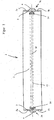
- FIG. 1 shows a cross section through the substrate carrier 1 according to the invention
- Substrate carrier has an inner space 2 for receiving at least one substrate 13.
- the interior is surrounded by an annular wall 3, perpendicular to the Center plane M of the substrate carrier extends.
- Means 14 may be provided for holding one or more substrates, e.g. are resiliently connected to the wall 3, wherein the substrate 13 (shown in dashed lines) is preferably arranged symmetrically to the center plane M.
- the holding devices 14 are shown only schematically, since the shape of each adapt to the substrate to be used is.
- the interior 2 is open on both sides perpendicular to the median plane M, both one-sided as well as two-sided machining processes of substrates are performed.
- On the outer circumference 3a of the wall 3 is a circumferential convex, to the median plane M. arranged symmetrical projection 4, whose apex lies in the median plane M.
- symmetrical projection 4 On the one side and the other side with respect to the median plane, i. in the Drawing above and below the median plane, and symmetrical to it two circumferential concave grooves 5a and 5b arranged.
- the projection 4 and the grooves 5a and 5b are for the Intervention provided with at least one holding and / or gripping device, the Substrate carrier either passive holds or actively engages him to the substrate support ring transport or handed over to other holding and gripping devices.
- FIG. 2 shows the holder of the substrate carrier 1 in a passive holding device (sprung tension pulley) 6; a roller 7 is replaced by a spring 8 against the projection 4 (in the Drawing) above the median plane M pressed, and a stop surface 6a of Holding device 6 serves as a stop on which the projection 4 with its surface 4a seated below the median plane M.
- a passive holding device 6 is the Substrate carrier 1 in the direction of arrow A on the roller 7 against the spring force of the spring. 8 rolling or sliding introduced to the stop on the surface 6a by pressure.
- the spring-loaded roller holds the substrate carrier with a defined Force.
- the substrate carrier can be centered when at the periphery of the ring at least three or more holding devices 6 with the sprung tension rollers are arranged.
- other form-fitting Holding systems are used, which engage with the structured surface of the wall. 3 of the substrate carrier can be brought.
- FIG. 3 shows a cross section through the outer wall 3 of the substrate carrier adapter system 1 in engagement with a first and second gripping device with gripping means 9a and 9b, respectively.
- the gripping devices each have a gripper finger 11, at the end of a roller 10th is arranged, which is in each case with a groove 5a and 5b of the substrate carrier 1 in engagement.
- the Radius of the groove 5a, 5b is slightly larger than the radius of the roller 10 so that perpendicular to Axis of the roller 10, an automatic alignment of the substrate carrier 1 takes place (the roller 10th strives for the lowest point of the groove 5a, 5b).
- FIG. 3 shows a case wherein a transfer from the first gripping device to the first gripping device is shown in FIG second gripping device takes place.
- the substrate carrier is still by the gripping device 9a the first gripping device held in the groove 5a, while the gripping device 9b of second gripping device has already intervened in the groove 5b. After removing the first gripping device (not shown) of the substrate carrier 1, this can by the second gripping device to be transported.
- FIG. 4 shows a cross section through the wall 3 of the substrate carrier adapter system 1 in FIG Intervention with an alternative gripping device, the two, three or more gripping devices each having a V-shaped annular groove 12 facing with its outer wall Surface 12a the convex projection 4 above and below the median plane M is tangent.
- the annular groove 12 is moved in the direction of arrow B to the projection 4.
- the substrate carrier 1 is directed perpendicular to the pressing direction B of Ring groove 12 automatically off, since the projection 4 to the stop on both sides of the surface 12a slides into the annular groove.
- the substrate carrier adapter system according to the invention can in the one or both sides Coating one or more substrates are used.
- the substrate carrier adapter system according to the invention can be used as a unitary and single Substrate Carrier Adapter System throughout the run through a facility used and also required by others during the process Treatment steps, e.g. a cleaning of the substrate, are used.
Landscapes
- Chemical & Material Sciences (AREA)
- Chemical Kinetics & Catalysis (AREA)
- Engineering & Computer Science (AREA)
- Materials Engineering (AREA)
- Mechanical Engineering (AREA)
- Metallurgy (AREA)
- Organic Chemistry (AREA)
- Physical Vapour Deposition (AREA)
- Container, Conveyance, Adherence, Positioning, Of Wafer (AREA)
- Chemical Vapour Deposition (AREA)
- Recrystallisation Techniques (AREA)
- Wire Bonding (AREA)
Abstract
Description
- Fig. 1
- einen Querschnitt durch den erfindungsgemäßen Substratträger,
- Fig. 2
- einen Querschnitt der Außenwand des erfindungsgemäßen Substratträgers im Eingriff mit einer Haltevorrichtung,
- Fig. 3
- einen Querschnitt der Außenwand des erfindungsgemäßen Substratträgers im Eingriff mit zwei Greifvorrichtungen, und
- Fig.4
- einen Querschnitt der Wand des erfindungsgemäßen Substratträgers im Eingriff mit einer weiteren Greifvorrichtung.
Claims (20)
- Substratträger (1), insbesondere zur Aufnahme eines beidseitig zu behandelnden oder zu beschichtenden Substrats (13), mit(a) einem Innenraum (2) zur Aufnahme mindestens eines Substrats (13),(b) einer ringförmigen Wand (3), die sich senkrecht zur Mittelebene (M) des Substratträgers (1) erstreckt und den Innenraum (2) seitlich begrenzt,(c) einem am Außenumfang (3a) der Wand (3) umlaufenden, konvexen Vorsprung (4), dessen Scheitelpunkt in der Mittelebene (M) liegt, und(d) zwei symmetrisch zur Mittelebene (M) und zum Vorsprung (4) umlaufenden konkaven Nuten (5a, 5b) zum Eingriff mit mindestens einer Halte- und/oder Greifeinrichtung.
- Substratträger (1) nach Anspruch 1, wobei das Substrat (13) durch mindestens zwei Substrathalter (14) an der Innenseite der Wand (3) gehalten wird.
- Substratträger (1) nach Anspruch 1 oder 2, wobei die ringförmige Wand (3) kreiszylindrisch ausgebildet ist.
- Substratträger (1) nach Anspruch 1 oder 2, wobei die Innenseite der ringförmigen Wand (3) konisch und die Außenseite der ringförmigen Wand (3) kreiszylindrisch ausgebildet ist.
- Vorrichtung zum Handhaben des Substratträgers (1) nach einem der Ansprüche 1 bis 4, mit mindestens zwei passiven Haltevorrichtungen (6) zum Positionieren am Umfang des Substratträgers (1) mit jeweils einer Rolle (7), die durch eine Feder (8) gegen den Vorsprung (4) auf der einen Seite bezüglich der Mittelebene (M) gedrückt wird, und einer Anschlagfläche (6a), auf der eine Fläche (4a) des Vorsprungs (4) auf der anderen Seite bezüglich der Mittelebene (M) aufsitzt.
- Vorrichtung nach Anspruch 5, wobei mindestens drei, vorzugsweise vier Haltevorrichtungen (6) zum Positionieren am Umfang des Substratträgers (1) vorgesehen sind.
- Vorrichtung nach Anspruch 5 oder 6, wobei der Substratträger (1) in Richtung des Pfeiles (A) rollend oder gleitend über die Rolle (7) gedrückt wird, bis die Fläche (4a) auf der Anschlagfläche (6a) aufsitzt, wobei die Rolle (7) den Substratträger (1) in dieser Position federnd und mit definierter Kraft lösbar verriegelt.
- Vorrichtung nach Anspruch 6 oder 7, wobei der Substratträger (1) durch die Haltevorrichtung (6) zentriert wird.
- Vorrichtung zum Greifen des Substratträgers (1) nach einem der Ansprüche 1 bis 4, mit mindestens zwei Greifeinrichtungen (9a oder 9b) zum Positionieren am Umfang des Substratträgers (1) mit jeweils einer Rolle (10), die in Eingriff mit einer der Nuten (5a, 5b) bringbar ist.
- Vorrichtung nach Anspruch 9, wobei mindestens drei, vorzugsweise vier Greifeinrichtungen (9a oder 9b) zum Positionieren am Umfang des Substratträgers (1) vorgesehen sind.
- Vorrichtung nach Anspruch 9 oder 10, wobei der Radius der Rolle (10) kleiner als der Radius der Nut (5a, 5b) ist, so daß beim Eingriff der Rolle (10) in die Nut (5a, 5b) der Substratträger (1) senkrecht zur Achse der Rolle (10) selbsttätig ausgerichtet wird.
- Verfahren zum Handhaben eines Substratträgers (1) nach einem der Ansprüche 1 bis 4 mittels der Vorrichtung nach Anspruch 9, 10 oder 11, wobei die Greifeinrichtung (9a oder 9b) an den Substratträger (1) heranfährt und die Rolle (10) in die Nut (5a oder 5b) eingreift, die Greifeinrichtung (9a oder 9b) den Substratträger (1) transportiert und anschließend den Eingriff der Rolle (10) in der Nut (5a oder 5b) löst.
- Verfahren nach Anspruch 12, wobei der Substratträger (1) mittels einer zweiten Vorrichtung nach Anspruch 9, 10 oder 11 ergriffen und nach Lösen der ersten Greifeinrichtung (9a) oder einer Haltevorrichtung (6) nach einem der Ansprüche 5 bis 8 von dem Substratträger (1) diesen übernimmt.
- Vorrichtung zum Handhaben des Substratträgers (1) nach einem der Ansprüche 1 bis 4, mit mehreren, vorzugsweise zwei Greifeinrichtungen zum Positionieren am Umfang des Substratträgers (1), die jeweils eine V-förmige Ringnut (12) aufweisen, deren dem Substratträger (1) zugewandte Fläche (12a) den Vorsprung (4) auf der einen Seite und auf der anderen Seite bezüglich der Mittelebene tangiert, wobei der Substratträger (1) senkrecht zur Andruckrichtung (B) der Ringnut (12) selbsttätig ausgerichtet wird.
- Verfahren zum Handhaben eines Substratträgers (1) nach einem der Ansprüche 1 bis 4 mittels der Vorrichtung nach Anspruch 14, wobei die Ringnut (12) in Radialrichtung (Pfeil B) von außen an den Substratträger (1) herangeführt und mit dem Vorsprung (4) in Eingriff gebracht wird, die Greifeinrichtung den Substratträger (1) transportiert und anschließend die Fläche (12a) in Radialrichtung nach außen von dem Vorsprung (4) entfernt.
- Verwendung des Substratträgers (1) nach einem der Ansprüche 1 bis 4, der Vorrichtung nach einem der Ansprüche 5 bis 11 oder 14 und des Verfahrens nach Anspruch 12, 13 oder 15 bei der ein- oder beidseitigen Beschichtung des Substrats.
- Verwendung nach Anspruch 16, bei der Beschichtung durch Kathodenzerstäubung.
- Verwendung nach Anspruch 17, wobei die Wand (3) des Substratträgers (1) als Anodenfläche dient.
- Verwendung nach Anspruch 16, bei CVD (chemical vapor deposition) Beschichtungsprozessen.
- Verwendung des Substratträgers (1) nach einem der Ansprüche 1 bis 4, der Vorrichtung nach einem der Ansprüche 5 bis 11 oder 14 und des Verfahrens nach Anspruch 12, 13 oder 15 bei der Reinigung des Substrats.
Applications Claiming Priority (2)
| Application Number | Priority Date | Filing Date | Title |
|---|---|---|---|
| DE10355679 | 2003-11-28 | ||
| DE10355679A DE10355679B4 (de) | 2003-11-28 | 2003-11-28 | Substratträger, Vorrichtung und Verfahren zum Handhaben des Substratträgers und Verwendung in Beschichtungsprozessen |
Publications (3)
| Publication Number | Publication Date |
|---|---|
| EP1538236A2 true EP1538236A2 (de) | 2005-06-08 |
| EP1538236A3 EP1538236A3 (de) | 2005-08-10 |
| EP1538236B1 EP1538236B1 (de) | 2008-05-21 |
Family
ID=34442326
Family Applications (1)
| Application Number | Title | Priority Date | Filing Date |
|---|---|---|---|
| EP04027863A Expired - Lifetime EP1538236B1 (de) | 2003-11-28 | 2004-11-24 | Substratträger |
Country Status (6)
| Country | Link |
|---|---|
| US (1) | US20050142290A1 (de) |
| EP (1) | EP1538236B1 (de) |
| JP (1) | JP2005200214A (de) |
| AT (1) | ATE396288T1 (de) |
| DE (2) | DE10355679B4 (de) |
| ES (1) | ES2305651T3 (de) |
Cited By (1)
| Publication number | Priority date | Publication date | Assignee | Title |
|---|---|---|---|---|
| WO2008040546A3 (de) * | 2006-10-04 | 2008-09-18 | Singulus Technologies Ag | Oberflächenbehandlungssystem und darin verwendbare lackiervorrichtung |
Families Citing this family (5)
| Publication number | Priority date | Publication date | Assignee | Title |
|---|---|---|---|---|
| DE102005045718B4 (de) * | 2005-09-24 | 2009-06-25 | Applied Materials Gmbh & Co. Kg | Träger für ein Substrat |
| DE102016214445A1 (de) | 2016-08-04 | 2018-02-08 | Meyer Burger (Germany) Ag | Anpassungsvorrichtung für Substratträger |
| CN111430279B (zh) * | 2020-04-30 | 2023-09-01 | 瑞安市荣海机电有限公司 | 一种准分子激光退火设备用基板支撑装置 |
| DE102021002293B4 (de) | 2021-04-30 | 2025-04-30 | Singulus Technologies Aktiengesellschaft | Substratträger mit Zentrierfunktion, Wechselstation mit einem Substratträger und Verfahren zum Behandeln eines Substrats |
| CN121451122B (zh) * | 2026-01-05 | 2026-04-07 | 中国人民解放军国防科技大学 | 一种矫正陶瓷片翘曲的镀膜工装及电极制备方法 |
Family Cites Families (11)
| Publication number | Priority date | Publication date | Assignee | Title |
|---|---|---|---|---|
| DE7707767U1 (de) * | 1977-03-14 | 1977-09-08 | Balzers Hochvakuum Gmbh, 6200 Wiesbaden | Halterung fuer substratplaettchen |
| DE2723284A1 (de) * | 1977-05-24 | 1978-12-07 | Leybold Heraeus Gmbh & Co Kg | Transporteinrichtung fuer die bewegung von gegenstaenden in abgeschlossenen raeumen |
| JPH01103983A (ja) * | 1988-09-19 | 1989-04-21 | Hitachi Ltd | 分子線エピタキシ装置用サセプタ |
| JP2747715B2 (ja) * | 1989-01-24 | 1998-05-06 | 株式会社日平トヤマ | 把握装置 |
| DE3919611A1 (de) * | 1989-06-15 | 1990-12-20 | Wacker Chemitronic | Haltevorrichtung zur aufnahme von scheibenfoermigen gegenstaenden, insbesondere halbleiterscheiben, und verfahren zu deren behandlung |
| DE69021952T2 (de) * | 1989-06-29 | 1996-05-15 | Applied Materials Inc | Vorrichtung zur Handhabung von Halbleiterplättchen. |
| DE4446179C2 (de) * | 1994-12-23 | 2003-08-21 | Leybold Optics Gmbh | Halterung für scheibenförmige Substrate |
| DE19605598C1 (de) * | 1996-02-15 | 1996-10-31 | Singulus Technologies Gmbh | Vorrichtung zum Greifen und Halten von Substraten |
| JPH11176916A (ja) * | 1997-12-11 | 1999-07-02 | Toshiba Mach Co Ltd | ウェーハ支持体 |
| JP2002307343A (ja) * | 2001-04-12 | 2002-10-23 | Matsushita Electric Ind Co Ltd | 薄板材の移載方法および装置 |
| JP2003124167A (ja) * | 2001-10-10 | 2003-04-25 | Sumitomo Heavy Ind Ltd | ウエハ支持部材及びこれを用いる両頭研削装置 |
-
2003
- 2003-11-28 DE DE10355679A patent/DE10355679B4/de not_active Expired - Fee Related
-
2004
- 2004-11-24 EP EP04027863A patent/EP1538236B1/de not_active Expired - Lifetime
- 2004-11-24 DE DE502004007214T patent/DE502004007214D1/de not_active Expired - Lifetime
- 2004-11-24 AT AT04027863T patent/ATE396288T1/de not_active IP Right Cessation
- 2004-11-24 ES ES04027863T patent/ES2305651T3/es not_active Expired - Lifetime
- 2004-11-26 US US10/998,206 patent/US20050142290A1/en not_active Abandoned
- 2004-11-29 JP JP2004344301A patent/JP2005200214A/ja active Pending
Cited By (1)
| Publication number | Priority date | Publication date | Assignee | Title |
|---|---|---|---|---|
| WO2008040546A3 (de) * | 2006-10-04 | 2008-09-18 | Singulus Technologies Ag | Oberflächenbehandlungssystem und darin verwendbare lackiervorrichtung |
Also Published As
| Publication number | Publication date |
|---|---|
| DE10355679A1 (de) | 2005-06-30 |
| EP1538236B1 (de) | 2008-05-21 |
| EP1538236A3 (de) | 2005-08-10 |
| DE10355679B4 (de) | 2008-08-14 |
| ATE396288T1 (de) | 2008-06-15 |
| US20050142290A1 (en) | 2005-06-30 |
| JP2005200214A (ja) | 2005-07-28 |
| ES2305651T3 (es) | 2008-11-01 |
| DE502004007214D1 (de) | 2008-07-03 |
Similar Documents
| Publication | Publication Date | Title |
|---|---|---|
| EP3337993B1 (de) | Verfahren zur herstellung von lagerkomponenten mittels einer fertigungsstrasse, fertigungsstrasse und fertigungsanlage | |
| EP1372186B1 (de) | Vorrichtung zur Flüssigkeitsbehandlung von scheibenförmigen Gegenständen | |
| DE69108908T2 (de) | Vorrichtung zur behandlung einer einzelnen waferscheibe. | |
| DE10216706B9 (de) | Verfahren zur Herstellung einer Projektionsscheinwerferlinse | |
| EP0528106A1 (de) | Vorrichtung zum selbsttätigen Giessen, Beschichten, Lackieren, Prüfen und Sortieren von Werkstücken | |
| DE69301352T2 (de) | Vorrichtung zum Spannen und Festhalten von zu formenden Glasscheiben in ihrer Position während ihrer Bearbeitung | |
| DE60032324T2 (de) | Wafer-Behandlungsvorrichtung | |
| DE102017117064A1 (de) | Werkstückaufnahme und Werkstückbearbeitungsverfahren | |
| DE102017213961A1 (de) | Ablöseverfahren und ablösevorrichtung | |
| DE102011009400A1 (de) | Vorrichtung zum Aufblocken von Brillengläsern | |
| DE102015106777A1 (de) | Verfahren sowie Inspektionssystem zur Ermittlung und Überprüfung des Oberflächenreinheitsgrades von industriell gereinigten Werkstücken oder Maschinenbauteilen | |
| DE10355679B4 (de) | Substratträger, Vorrichtung und Verfahren zum Handhaben des Substratträgers und Verwendung in Beschichtungsprozessen | |
| DE102017121557A1 (de) | Verfahren und Vorrichtung zur Förderung und Positionierung von Werkstücken | |
| EP3181291B1 (de) | Werkstück mit optischem linsenrohling, verfahren zu dessen herstellung und verfahren zu dessen bearbeitung | |
| DE69603724T2 (de) | Vorrichtung zur oberflächenbehandlung | |
| EP0519093A1 (de) | Verfahren und Vorrichtung zum Entgraten von Rohrstirnseiten | |
| EP1073599B1 (de) | Vorrichtung und verfahren zum handhaben von substraten | |
| EP3666402A2 (de) | Dampfreinigungsanlage und beschichtungsanlage mit dampfreinigung | |
| DE102020101429A1 (de) | Vorrichtung und Verfahren zum Spannen und Bearbeiten eines rotationssym-metrischen Werkstücks | |
| DE3127047C2 (de) | Vorrichtung zum Einlegen von flexiblen Federringen in Lippendichtungsringe | |
| DE102022107995A1 (de) | Verteiltes Montagesystem und Verfahren zum Montieren eines Werkstücks | |
| DE102017111618B4 (de) | Vorrichtung, System und Verfahren zur Trocknung einer Halbleiterscheibe | |
| DE102020114006A1 (de) | Vorrichtung und Verfahren zum Honen von Tonnenrollen | |
| EP4292758B1 (de) | Vorrichtung für das bearbeiten eines scheibenrohlings durch schleifen | |
| DE2724579C3 (de) | Verfahren zum Reinigen der Oberflache einer Mehrzahl von Substraten für Halbleiterbauelemente und Vorrichtung zur Durchführung dieses Verfahrens |
Legal Events
| Date | Code | Title | Description |
|---|---|---|---|
| PUAI | Public reference made under article 153(3) epc to a published international application that has entered the european phase |
Free format text: ORIGINAL CODE: 0009012 |
|
| AK | Designated contracting states |
Kind code of ref document: A2 Designated state(s): AT BE BG CH CY CZ DE DK EE ES FI FR GB GR HU IE IS IT LI LU MC NL PL PT RO SE SI SK TR |
|
| AX | Request for extension of the european patent |
Extension state: AL HR LT LV MK YU |
|
| PUAL | Search report despatched |
Free format text: ORIGINAL CODE: 0009013 |
|
| AK | Designated contracting states |
Kind code of ref document: A3 Designated state(s): AT BE BG CH CY CZ DE DK EE ES FI FR GB GR HU IE IS IT LI LU MC NL PL PT RO SE SI SK TR |
|
| AX | Request for extension of the european patent |
Extension state: AL HR LT LV MK YU |
|
| RIC1 | Information provided on ipc code assigned before grant |
Ipc: 7C 23C 14/50 B Ipc: 7C 23C 14/56 B Ipc: 7C 23C 16/458 A |
|
| 17P | Request for examination filed |
Effective date: 20051202 |
|
| AKX | Designation fees paid |
Designated state(s): AT BE BG CH CY CZ DE DK EE ES FI FR GB GR HU IE IS IT LI LU MC NL PL PT RO SE SI SK TR |
|
| 17Q | First examination report despatched |
Effective date: 20060317 |
|
| GRAP | Despatch of communication of intention to grant a patent |
Free format text: ORIGINAL CODE: EPIDOSNIGR1 |
|
| GRAS | Grant fee paid |
Free format text: ORIGINAL CODE: EPIDOSNIGR3 |
|
| GRAA | (expected) grant |
Free format text: ORIGINAL CODE: 0009210 |
|
| AK | Designated contracting states |
Kind code of ref document: B1 Designated state(s): AT BE BG CH CY CZ DE DK EE ES FI FR GB GR HU IE IS IT LI LU MC NL PL PT RO SE SI SK TR |
|
| REG | Reference to a national code |
Ref country code: GB Ref legal event code: FG4D Free format text: NOT ENGLISH |
|
| REG | Reference to a national code |
Ref country code: CH Ref legal event code: EP |
|
| REF | Corresponds to: |
Ref document number: 502004007214 Country of ref document: DE Date of ref document: 20080703 Kind code of ref document: P |
|
| REG | Reference to a national code |
Ref country code: IE Ref legal event code: FG4D Free format text: LANGUAGE OF EP DOCUMENT: GERMAN |
|
| PG25 | Lapsed in a contracting state [announced via postgrant information from national office to epo] |
Ref country code: SI Free format text: LAPSE BECAUSE OF FAILURE TO SUBMIT A TRANSLATION OF THE DESCRIPTION OR TO PAY THE FEE WITHIN THE PRESCRIBED TIME-LIMIT Effective date: 20080521 |
|
| REG | Reference to a national code |
Ref country code: CH Ref legal event code: NV Representative=s name: VOSSIUS & PARTNER |
|
| PG25 | Lapsed in a contracting state [announced via postgrant information from national office to epo] |
Ref country code: FI Free format text: LAPSE BECAUSE OF FAILURE TO SUBMIT A TRANSLATION OF THE DESCRIPTION OR TO PAY THE FEE WITHIN THE PRESCRIBED TIME-LIMIT Effective date: 20080521 |
|
| REG | Reference to a national code |
Ref country code: ES Ref legal event code: FG2A Ref document number: 2305651 Country of ref document: ES Kind code of ref document: T3 |
|
| PG25 | Lapsed in a contracting state [announced via postgrant information from national office to epo] |
Ref country code: PL Free format text: LAPSE BECAUSE OF FAILURE TO SUBMIT A TRANSLATION OF THE DESCRIPTION OR TO PAY THE FEE WITHIN THE PRESCRIBED TIME-LIMIT Effective date: 20080521 |
|
| PG25 | Lapsed in a contracting state [announced via postgrant information from national office to epo] |
Ref country code: IS Free format text: LAPSE BECAUSE OF FAILURE TO SUBMIT A TRANSLATION OF THE DESCRIPTION OR TO PAY THE FEE WITHIN THE PRESCRIBED TIME-LIMIT Effective date: 20080921 |
|
| REG | Reference to a national code |
Ref country code: IE Ref legal event code: FD4D |
|
| PG25 | Lapsed in a contracting state [announced via postgrant information from national office to epo] |
Ref country code: IE Free format text: LAPSE BECAUSE OF FAILURE TO SUBMIT A TRANSLATION OF THE DESCRIPTION OR TO PAY THE FEE WITHIN THE PRESCRIBED TIME-LIMIT Effective date: 20080521 Ref country code: SE Free format text: LAPSE BECAUSE OF FAILURE TO SUBMIT A TRANSLATION OF THE DESCRIPTION OR TO PAY THE FEE WITHIN THE PRESCRIBED TIME-LIMIT Effective date: 20080821 Ref country code: CZ Free format text: LAPSE BECAUSE OF FAILURE TO SUBMIT A TRANSLATION OF THE DESCRIPTION OR TO PAY THE FEE WITHIN THE PRESCRIBED TIME-LIMIT Effective date: 20080521 Ref country code: DK Free format text: LAPSE BECAUSE OF FAILURE TO SUBMIT A TRANSLATION OF THE DESCRIPTION OR TO PAY THE FEE WITHIN THE PRESCRIBED TIME-LIMIT Effective date: 20080521 Ref country code: PT Free format text: LAPSE BECAUSE OF FAILURE TO SUBMIT A TRANSLATION OF THE DESCRIPTION OR TO PAY THE FEE WITHIN THE PRESCRIBED TIME-LIMIT Effective date: 20081021 |
|
| PG25 | Lapsed in a contracting state [announced via postgrant information from national office to epo] |
Ref country code: RO Free format text: LAPSE BECAUSE OF FAILURE TO SUBMIT A TRANSLATION OF THE DESCRIPTION OR TO PAY THE FEE WITHIN THE PRESCRIBED TIME-LIMIT Effective date: 20080521 Ref country code: SK Free format text: LAPSE BECAUSE OF FAILURE TO SUBMIT A TRANSLATION OF THE DESCRIPTION OR TO PAY THE FEE WITHIN THE PRESCRIBED TIME-LIMIT Effective date: 20080521 |
|
| PLBE | No opposition filed within time limit |
Free format text: ORIGINAL CODE: 0009261 |
|
| STAA | Information on the status of an ep patent application or granted ep patent |
Free format text: STATUS: NO OPPOSITION FILED WITHIN TIME LIMIT |
|
| 26N | No opposition filed |
Effective date: 20090224 |
|
| PG25 | Lapsed in a contracting state [announced via postgrant information from national office to epo] |
Ref country code: BG Free format text: LAPSE BECAUSE OF FAILURE TO SUBMIT A TRANSLATION OF THE DESCRIPTION OR TO PAY THE FEE WITHIN THE PRESCRIBED TIME-LIMIT Effective date: 20080821 Ref country code: EE Free format text: LAPSE BECAUSE OF FAILURE TO SUBMIT A TRANSLATION OF THE DESCRIPTION OR TO PAY THE FEE WITHIN THE PRESCRIBED TIME-LIMIT Effective date: 20080521 |
|
| BERE | Be: lapsed |
Owner name: SINGULUS TECHNOLOGIES A.G. Effective date: 20081130 |
|
| PG25 | Lapsed in a contracting state [announced via postgrant information from national office to epo] |
Ref country code: MC Free format text: LAPSE BECAUSE OF NON-PAYMENT OF DUE FEES Effective date: 20081130 |
|
| PG25 | Lapsed in a contracting state [announced via postgrant information from national office to epo] |
Ref country code: BE Free format text: LAPSE BECAUSE OF NON-PAYMENT OF DUE FEES Effective date: 20081130 |
|
| PG25 | Lapsed in a contracting state [announced via postgrant information from national office to epo] |
Ref country code: AT Free format text: LAPSE BECAUSE OF NON-PAYMENT OF DUE FEES Effective date: 20081124 |
|
| PGFP | Annual fee paid to national office [announced via postgrant information from national office to epo] |
Ref country code: ES Payment date: 20091125 Year of fee payment: 6 |
|
| PGFP | Annual fee paid to national office [announced via postgrant information from national office to epo] |
Ref country code: NL Payment date: 20091124 Year of fee payment: 6 |
|
| PGFP | Annual fee paid to national office [announced via postgrant information from national office to epo] |
Ref country code: FR Payment date: 20091203 Year of fee payment: 6 Ref country code: GB Payment date: 20091124 Year of fee payment: 6 Ref country code: IT Payment date: 20091125 Year of fee payment: 6 |
|
| PGFP | Annual fee paid to national office [announced via postgrant information from national office to epo] |
Ref country code: DE Payment date: 20091229 Year of fee payment: 6 |
|
| PG25 | Lapsed in a contracting state [announced via postgrant information from national office to epo] |
Ref country code: HU Free format text: LAPSE BECAUSE OF FAILURE TO SUBMIT A TRANSLATION OF THE DESCRIPTION OR TO PAY THE FEE WITHIN THE PRESCRIBED TIME-LIMIT Effective date: 20081122 Ref country code: CY Free format text: LAPSE BECAUSE OF FAILURE TO SUBMIT A TRANSLATION OF THE DESCRIPTION OR TO PAY THE FEE WITHIN THE PRESCRIBED TIME-LIMIT Effective date: 20080521 Ref country code: LU Free format text: LAPSE BECAUSE OF NON-PAYMENT OF DUE FEES Effective date: 20081124 |
|
| PG25 | Lapsed in a contracting state [announced via postgrant information from national office to epo] |
Ref country code: TR Free format text: LAPSE BECAUSE OF FAILURE TO SUBMIT A TRANSLATION OF THE DESCRIPTION OR TO PAY THE FEE WITHIN THE PRESCRIBED TIME-LIMIT Effective date: 20080521 |
|
| PG25 | Lapsed in a contracting state [announced via postgrant information from national office to epo] |
Ref country code: GR Free format text: LAPSE BECAUSE OF FAILURE TO SUBMIT A TRANSLATION OF THE DESCRIPTION OR TO PAY THE FEE WITHIN THE PRESCRIBED TIME-LIMIT Effective date: 20080822 |
|
| PGFP | Annual fee paid to national office [announced via postgrant information from national office to epo] |
Ref country code: CH Payment date: 20101130 Year of fee payment: 7 |
|
| REG | Reference to a national code |
Ref country code: NL Ref legal event code: V1 Effective date: 20110601 |
|
| GBPC | Gb: european patent ceased through non-payment of renewal fee |
Effective date: 20101124 |
|
| REG | Reference to a national code |
Ref country code: FR Ref legal event code: ST Effective date: 20110801 |
|
| PG25 | Lapsed in a contracting state [announced via postgrant information from national office to epo] |
Ref country code: NL Free format text: LAPSE BECAUSE OF NON-PAYMENT OF DUE FEES Effective date: 20110601 |
|
| REG | Reference to a national code |
Ref country code: DE Ref legal event code: R119 Ref document number: 502004007214 Country of ref document: DE Effective date: 20110601 Ref country code: DE Ref legal event code: R119 Ref document number: 502004007214 Country of ref document: DE Effective date: 20110531 |
|
| PG25 | Lapsed in a contracting state [announced via postgrant information from national office to epo] |
Ref country code: FR Free format text: LAPSE BECAUSE OF NON-PAYMENT OF DUE FEES Effective date: 20101130 |
|
| PG25 | Lapsed in a contracting state [announced via postgrant information from national office to epo] |
Ref country code: GB Free format text: LAPSE BECAUSE OF NON-PAYMENT OF DUE FEES Effective date: 20101124 |
|
| PG25 | Lapsed in a contracting state [announced via postgrant information from national office to epo] |
Ref country code: IT Free format text: LAPSE BECAUSE OF NON-PAYMENT OF DUE FEES Effective date: 20101124 |
|
| REG | Reference to a national code |
Ref country code: ES Ref legal event code: FD2A Effective date: 20120110 |
|
| PG25 | Lapsed in a contracting state [announced via postgrant information from national office to epo] |
Ref country code: ES Free format text: LAPSE BECAUSE OF NON-PAYMENT OF DUE FEES Effective date: 20101125 |
|
| REG | Reference to a national code |
Ref country code: CH Ref legal event code: PL |
|
| PG25 | Lapsed in a contracting state [announced via postgrant information from national office to epo] |
Ref country code: LI Free format text: LAPSE BECAUSE OF NON-PAYMENT OF DUE FEES Effective date: 20111130 Ref country code: CH Free format text: LAPSE BECAUSE OF NON-PAYMENT OF DUE FEES Effective date: 20111130 |
|
| PG25 | Lapsed in a contracting state [announced via postgrant information from national office to epo] |
Ref country code: DE Free format text: LAPSE BECAUSE OF NON-PAYMENT OF DUE FEES Effective date: 20110531 |