EP1538287A1 - Türaussengriff - Google Patents
Türaussengriff Download PDFInfo
- Publication number
- EP1538287A1 EP1538287A1 EP03027955A EP03027955A EP1538287A1 EP 1538287 A1 EP1538287 A1 EP 1538287A1 EP 03027955 A EP03027955 A EP 03027955A EP 03027955 A EP03027955 A EP 03027955A EP 1538287 A1 EP1538287 A1 EP 1538287A1
- Authority
- EP
- European Patent Office
- Prior art keywords
- lever
- handle
- bearing
- housing part
- door
- Prior art date
- Legal status (The legal status is an assumption and is not a legal conclusion. Google has not performed a legal analysis and makes no representation as to the accuracy of the status listed.)
- Granted
Links
Images
Classifications
-
- E—FIXED CONSTRUCTIONS
- E05—LOCKS; KEYS; WINDOW OR DOOR FITTINGS; SAFES
- E05B—LOCKS; ACCESSORIES THEREFOR; HANDCUFFS
- E05B77/00—Vehicle locks characterised by special functions or purposes
- E05B77/02—Vehicle locks characterised by special functions or purposes for accident situations
- E05B77/04—Preventing unwanted lock actuation, e.g. unlatching, at the moment of collision
-
- B—PERFORMING OPERATIONS; TRANSPORTING
- B29—WORKING OF PLASTICS; WORKING OF SUBSTANCES IN A PLASTIC STATE IN GENERAL
- B29C—SHAPING OR JOINING OF PLASTICS; SHAPING OF MATERIAL IN A PLASTIC STATE, NOT OTHERWISE PROVIDED FOR; AFTER-TREATMENT OF THE SHAPED PRODUCTS, e.g. REPAIRING
- B29C45/00—Injection moulding, i.e. forcing the required volume of moulding material through a nozzle into a closed mould; Apparatus therefor
- B29C45/17—Component parts, details or accessories; Auxiliary operations
- B29C45/1703—Introducing an auxiliary fluid into the mould
- B29C45/1704—Introducing an auxiliary fluid into the mould the fluid being introduced into the interior of the injected material which is still in a molten state, e.g. for producing hollow articles
Definitions
- the invention relates to an outside door handle for a locking device of a Motor vehicle according to the preamble of claim 1.
- Such an outside door handle has a fastened to the vehicle door Housing part and a handle bar, which on the housing part at one end is mounted pivotably about a fixed bearing by means of a bearing lever and on the another end having an actuating lever, which is connected to the locking device is coupled.
- a mass is arranged such that it in the event of a crash, a counter-torque on the handle bar or a handle with the handle connected part exerts, such that due to the mass acceleration no Opening the door can be done.
- the invention is therefore based on the object, an outside door handle of to create the aforementioned type, in which it is also strong Sheet metal deformation not opening the door in the event of a side impact can come.
- the invention advantageously provides that the bearing lever for Preventing the door from opening in the event of a side impact Force effect between the housing part and the handle yields and thus preventing outward forces acting on the operating lever act.
- the door panel between the housing part and deform the handle so that a force is exerted on the handle is that causes the handle bar to an opening movement.
- the bearing lever of two articulated with each other connected lever parts consists.
- the hingedly interconnected lever parts can be ejected via a Blocking be held in their mutual angular position, the Locking element when exercising a torque on the lever parts ejected is.
- This locking element is not necessarily for the function of the bearing lever necessary, but can be used in the manufacture and installation of the outside door handle Be advantageous because the position of the lever parts is fixed by the locking element.
- the bearing lever and the operating lever are preferably in the handle lockable.
- the bearing lever and the operating lever as a separate Parts are provided which can be used in the handle bar or in the Handlebars can be locked, different materials for the lever and be used the handle.
- the handle can be made of one Injection hollow part exist. Due to the separate production of the bearing lever and the actuating lever does not cause large accumulations of material on the End of the handle bar, resulting in the manufacture of the handle as Spritzg devishohlteil is advantageous. It is also when painting or chrome plating of the handle not necessary to mask tightly formed bearing levers and operating levers, so that the production can be simplified.
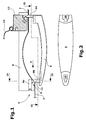
- the outside door handle shown in Fig. 1 comprises a housing part 4, from the inside is mounted on a door 2 of a vehicle.
- a handle bar 6 articulated hooked to a fixed bearing 9, wherein on the another end of the housing part 4, an actuating lever 10 of the handle bracket by engages the door 2 through the inside and with a pivot arm 12th is coupled, which is pivotable about a vertical axis.
- the pivot arm 12 is also pivoted, wherein a lock, not shown in the drawing, of a closing device a cable 14 is opened so that the door 2 of the vehicle can be opened can.
- the pivot arm 12, which in the event of a side impact for a To provide counter-torque is not mandatory and here only by way of example shown.
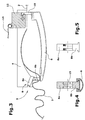
- the door panel of the door 2 deforms at a side impact such that the handle bar 6 by the occurring Deformation of the door 2 is pressed outwards.
- the bearing lever 8 is made in two parts and consists of two articulated interconnected lever parts 8a, 8b, which in the case of a force can pivot against each other, so that in a side impact occurring forces the handle bar 6 not on the side of the actuating lever 10th but press outward on the fixed bearing side. That way you can no such high forces are exerted on the operating lever 10 that this can open the door 2 in a side impact.
- the bearing lever 8 may be provided with a locking element 11, which in a Recess 15 (Fig. 4) sits.
- the blocking element 11 has the task, the two To hold lever parts 8a, 8b of the bearing lever 8 in position. This is For example, during assembly advantageous when the two lever parts 8a, 8b of the Bearing lever 8 is not held solely due to friction in its angular position become.
- the blocking element 11 is replaced by an ejector 13 of the lever part 8a ejected.
- the handle bar 6 is preferably made of an injection molded hollow part, which in the Gas mecanicakukane is produced. It is particularly advantageous that the bearing lever 8 and the operating lever 10 as separate parts in the handle 6 with the help of the recesses 16, 18 in handle bar 6 can be used. That's it possible for the bearing lever 8 and the operating lever 10 of the material of Handle to use 6 different materials. Also, at the Production of the handle bar 6 avoided that at the ends of the handle bar Material accumulations exist that in the manufacture of an injection molded hollow part Can cause difficulties.
Landscapes
- Lock And Its Accessories (AREA)
Abstract
Description
- Fig. 1
- einen Türaußengriff in seiner normalen, unbetätigten Stellung,
- Fig. 2
- eine Ansicht entlang der Linie II, II in Fig. 1,
- Fig. 3
- den Türaußengriff bei einem Seitenaufprall gegen die Tür,
- Fig. 4
- einen Querschnitt durch den im Griffbügel montierten Lagerhebel und
- Fig. 5
- eine Seitenansicht des Lagerhebels.
Claims (7)
- Türaußengriff für eine Schließeinrichtung eines Kraftfahrzeuges mit einem an einer Tür (2) befestigten Gehäuseteil (4) und einem Griffbügel (6), der in dem Gehäuseteil (4) an einem Ende mittels eines Lagerhebels (8) um ein Festlager (9) schwenkbar gelagert ist und an dem anderen Ende einen Betätigungshebel (10) aufweist, der mit der Schließeinrichtung gekoppelt ist,
dadurch gekennzeichnet, dass der Lagerhebel (8) zum Verhindern des Öffnen der Tür (2) bei einem Seitenaufprall infolge einer Krafteinwirkung zwischen dem Gehäuseteil (4) und dem Griffbügel (6) nachgibt und damit verhindert, dass auf den Betätigungshebel (10) nach außen wirkende Kräfte einwirken. - Türaußengriff nach Anspruch 1, dadurch gekennzeichnet, dass der Lagerhebel (8) aus zwei gelenkig miteinander verbundenen Teilen (8a, 8b) besteht.
- Türaußengriff nach Anspruch 2, dadurch gekennzeichnet, dass die gelenkig miteinander verbundenen Hebelteile (8a, 8b) über ein auswerfbares Sperrelement (11) in der gegenseitigen Winkellage gehalten sind, wobei bei Ausübung eines Drehmomentes auf den Lagerhebel (8) das Sperrelement (11) auswerfbar ist.
- Türaußengriff nach Anspruch 1, dadurch gekennzeichnet, dass ein Lagerhebel (8) aus zwei über eine Sollbruchstelle verbundenen Hebelteilen besteht.
- Türaußengriff nach einem der Ansprüche 1 bis 4, dadurch gekennzeichnet, dass der Lagerhebel (8) und der Betätigungshebel (10) mit dem Griffbügel (6) koppelbar sind.
- Türaußengriff nach einem der Ansprüche 1 bis 5, dadurch gekennzeichnet, dass der Griffbügel (6) aus einem Spritzgußhohlteil besteht.
- Türaußengriff Schließeinrichtung eines Kraftfahrzeuges mit einem an einer Tür (2) befestigten Gehäuseteil (4) und einem Griffbügel (6), der in dem Gehäuseteil (4) an einem Ende mittels eines Lagerhebels (8) um ein Festlager (9) schwenkbar gelagert ist und an dem anderen Ende einen Betätigungshebel (10) aufweist, der mit der Schließeinrichtung gekoppelt ist , dadurch gekennzeichnet, dass der Griffbügel (6) aus einem Spritzgußhohlteil besteht und dass der Lagerhebel (8) und der Betätigungshebel (10) mit dem Griffbügel (6) koppelbar sind.
Priority Applications (3)
| Application Number | Priority Date | Filing Date | Title |
|---|---|---|---|
| EP03027955A EP1538287B1 (de) | 2003-12-04 | 2003-12-04 | Türaussengriff |
| DE50309214T DE50309214D1 (de) | 2003-12-04 | 2003-12-04 | Türaussengriff |
| AT03027955T ATE386862T1 (de) | 2003-12-04 | 2003-12-04 | Türaussengriff |
Applications Claiming Priority (1)
| Application Number | Priority Date | Filing Date | Title |
|---|---|---|---|
| EP03027955A EP1538287B1 (de) | 2003-12-04 | 2003-12-04 | Türaussengriff |
Publications (2)
| Publication Number | Publication Date |
|---|---|
| EP1538287A1 true EP1538287A1 (de) | 2005-06-08 |
| EP1538287B1 EP1538287B1 (de) | 2008-02-20 |
Family
ID=34442964
Family Applications (1)
| Application Number | Title | Priority Date | Filing Date |
|---|---|---|---|
| EP03027955A Expired - Lifetime EP1538287B1 (de) | 2003-12-04 | 2003-12-04 | Türaussengriff |
Country Status (3)
| Country | Link |
|---|---|
| EP (1) | EP1538287B1 (de) |
| AT (1) | ATE386862T1 (de) |
| DE (1) | DE50309214D1 (de) |
Cited By (5)
| Publication number | Priority date | Publication date | Assignee | Title |
|---|---|---|---|---|
| FR2897575A1 (fr) * | 2006-02-22 | 2007-08-24 | Renault Sas | Porte de vehicule automobile pourvue d'un dispositif de detection d'une collision laterale. |
| DE102008062214A1 (de) * | 2008-12-13 | 2010-07-08 | Dr.Ing.H.C.F.Porsche Aktiengesellschaft | Türgriffeinrichtung |
| CN103046815A (zh) * | 2011-10-13 | 2013-04-17 | 霍弗·霍斯贝克及弗斯特两合公司 | 带有至少部分地作为平衡重的电子部件的把手 |
| US10190341B2 (en) * | 2016-09-12 | 2019-01-29 | Hyundai Motor Company | Door outside handle |
| WO2019238541A1 (de) * | 2018-06-11 | 2019-12-19 | Volkswagen Aktiengesellschaft | Einrichtung zur aufrechterhaltung eines verriegelten zustands einer kraftfahrzeugtür und kraftfahrzeug |
Citations (3)
| Publication number | Priority date | Publication date | Assignee | Title |
|---|---|---|---|---|
| DE19610200A1 (de) * | 1996-03-15 | 1997-09-18 | Valeo Deutschland Gmbh & Co | Türaußengriff |
| DE19936956A1 (de) * | 1999-08-05 | 2001-02-08 | Witte Velbert Gmbh & Co Kg | Verfahren zum Herstellen eines Kunststofformteils |
| WO2002014636A1 (de) * | 2000-08-11 | 2002-02-21 | Brose Fahrzeugteile Gmbh & Co. Kg, Coburg | Schliesseinrichtung für eine fahrzeugtür |
-
2003
- 2003-12-04 DE DE50309214T patent/DE50309214D1/de not_active Expired - Lifetime
- 2003-12-04 EP EP03027955A patent/EP1538287B1/de not_active Expired - Lifetime
- 2003-12-04 AT AT03027955T patent/ATE386862T1/de not_active IP Right Cessation
Patent Citations (3)
| Publication number | Priority date | Publication date | Assignee | Title |
|---|---|---|---|---|
| DE19610200A1 (de) * | 1996-03-15 | 1997-09-18 | Valeo Deutschland Gmbh & Co | Türaußengriff |
| DE19936956A1 (de) * | 1999-08-05 | 2001-02-08 | Witte Velbert Gmbh & Co Kg | Verfahren zum Herstellen eines Kunststofformteils |
| WO2002014636A1 (de) * | 2000-08-11 | 2002-02-21 | Brose Fahrzeugteile Gmbh & Co. Kg, Coburg | Schliesseinrichtung für eine fahrzeugtür |
Cited By (7)
| Publication number | Priority date | Publication date | Assignee | Title |
|---|---|---|---|---|
| FR2897575A1 (fr) * | 2006-02-22 | 2007-08-24 | Renault Sas | Porte de vehicule automobile pourvue d'un dispositif de detection d'une collision laterale. |
| DE102008062214A1 (de) * | 2008-12-13 | 2010-07-08 | Dr.Ing.H.C.F.Porsche Aktiengesellschaft | Türgriffeinrichtung |
| DE102008062214B4 (de) | 2008-12-13 | 2023-07-20 | Dr. Ing. H.C. F. Porsche Aktiengesellschaft | Türgriffeinrichtung |
| CN103046815A (zh) * | 2011-10-13 | 2013-04-17 | 霍弗·霍斯贝克及弗斯特两合公司 | 带有至少部分地作为平衡重的电子部件的把手 |
| CN103046815B (zh) * | 2011-10-13 | 2017-03-01 | 霍弗·霍斯贝克及弗斯特两合公司 | 带有至少部分地作为平衡重的电子部件的把手 |
| US10190341B2 (en) * | 2016-09-12 | 2019-01-29 | Hyundai Motor Company | Door outside handle |
| WO2019238541A1 (de) * | 2018-06-11 | 2019-12-19 | Volkswagen Aktiengesellschaft | Einrichtung zur aufrechterhaltung eines verriegelten zustands einer kraftfahrzeugtür und kraftfahrzeug |
Also Published As
| Publication number | Publication date |
|---|---|
| EP1538287B1 (de) | 2008-02-20 |
| DE50309214D1 (de) | 2008-04-03 |
| ATE386862T1 (de) | 2008-03-15 |
Similar Documents
| Publication | Publication Date | Title |
|---|---|---|
| EP0681943B1 (de) | Befestigungsvorrichtung | |
| DE4421903A1 (de) | Aufbau für ein Sprungwerkschloß | |
| EP3394371B1 (de) | Sicherheitsvorrichtung für ein kraftfahrzeug mit einer drehfalle und einer vorraststellung und einer hauptraststellung | |
| EP0970286B1 (de) | Hebelverschluss | |
| EP3394372B1 (de) | Sicherheitsvorrichtung für ein kraftfahrzeug mit einer drehfalle und einer auswurffeder | |
| EP0630802A2 (de) | Sicherungseinrichtung für Fahrräder | |
| DE3400753A1 (de) | Aussenschwingtuer fuer fahrzeuge und ihre betaetigungsvorrichtung | |
| DE60112143T2 (de) | Rückhalteteil für ein Kraftfahrzeugschloss, Verfahren zu seiner Herstellung und Schloss versehen mit einem solchen Rückhalteteil | |
| DE102017216920A1 (de) | Türgriffeinrichtung für eine Tür eines Kraftfahrzeugs, Tür, Kraftfahrzeug | |
| DE102010000654A1 (de) | Zweirad | |
| DE102009050875B4 (de) | Vorrichtung zum Öffnen und Schließen von Fenstern an Wohnwagen, Wohnmobilen und dergleichen | |
| EP1538287B1 (de) | Türaussengriff | |
| EP0113655B2 (de) | Türöffner und -schliesser | |
| DE4446464A1 (de) | Schloß, insbesondere für Autotüren | |
| EP1817205B1 (de) | Staufachvorrichtung | |
| DE102009040409A1 (de) | Scharnier und Verfahren zum Betreiben eines Scharniers | |
| DE102005033098B4 (de) | Heckklappe für ein Kraftfahrzeug | |
| DE102010053179A1 (de) | Kraftfahrzeugtürverschluss | |
| DE4107219A1 (de) | Schloss mit hilfsmotor, insbesondere tuerschloss fuer ein kraftfahrzeug | |
| DE3246396C2 (de) | Ausstellvorrichtung, insbesondere für Klappfenster von Kraftfahrzeugen, für Autohebedächer od. dgl. | |
| DE10008497B4 (de) | Feststellmechanismus für Schiebetür | |
| DE3920498C2 (de) | Mehrfachverriegelung | |
| DE102010026764A1 (de) | Betätigungseinrichtung für eine Verriegelungsvorrichtung eines Kraftwagens | |
| DE2924551A1 (de) | Tuerkonstruktion fuer fahrzeuge, bestehend aus einer ein- oder zweifluegeligen tuer | |
| DE4311339C1 (de) | Vorrichtung zur Herstellung einer kraftflußübertragenden Verbindung zwischen Fahrzeugtür und Fahrzeugkarosserie eines Kraftfahrzeugs |
Legal Events
| Date | Code | Title | Description |
|---|---|---|---|
| PUAI | Public reference made under article 153(3) epc to a published international application that has entered the european phase |
Free format text: ORIGINAL CODE: 0009012 |
|
| 17P | Request for examination filed |
Effective date: 20040518 |
|
| AK | Designated contracting states |
Kind code of ref document: A1 Designated state(s): AT BE BG CH CY CZ DE DK EE ES FI FR GB GR HU IE IT LI LU MC NL PT RO SE SI SK TR |
|
| AX | Request for extension of the european patent |
Extension state: AL LT LV MK |
|
| AKX | Designation fees paid |
Designated state(s): AT BE BG CH CY CZ DE DK EE ES FI FR GB GR HU IE IT LI LU MC NL PT RO SE SI SK TR |
|
| GRAP | Despatch of communication of intention to grant a patent |
Free format text: ORIGINAL CODE: EPIDOSNIGR1 |
|
| GRAS | Grant fee paid |
Free format text: ORIGINAL CODE: EPIDOSNIGR3 |
|
| GRAA | (expected) grant |
Free format text: ORIGINAL CODE: 0009210 |
|
| AK | Designated contracting states |
Kind code of ref document: B1 Designated state(s): AT BE BG CH CY CZ DE DK EE ES FI FR GB GR HU IE IT LI LU MC NL PT RO SE SI SK TR |
|
| REG | Reference to a national code |
Ref country code: GB Ref legal event code: FG4D Free format text: NOT ENGLISH |
|
| REG | Reference to a national code |
Ref country code: CH Ref legal event code: EP |
|
| REG | Reference to a national code |
Ref country code: IE Ref legal event code: FG4D Free format text: LANGUAGE OF EP DOCUMENT: GERMAN |
|
| REF | Corresponds to: |
Ref document number: 50309214 Country of ref document: DE Date of ref document: 20080403 Kind code of ref document: P |
|
| PG25 | Lapsed in a contracting state [announced via postgrant information from national office to epo] |
Ref country code: ES Free format text: LAPSE BECAUSE OF FAILURE TO SUBMIT A TRANSLATION OF THE DESCRIPTION OR TO PAY THE FEE WITHIN THE PRESCRIBED TIME-LIMIT Effective date: 20080531 Ref country code: FI Free format text: LAPSE BECAUSE OF FAILURE TO SUBMIT A TRANSLATION OF THE DESCRIPTION OR TO PAY THE FEE WITHIN THE PRESCRIBED TIME-LIMIT Effective date: 20080220 |
|
| NLV1 | Nl: lapsed or annulled due to failure to fulfill the requirements of art. 29p and 29m of the patents act | ||
| PG25 | Lapsed in a contracting state [announced via postgrant information from national office to epo] |
Ref country code: SI Free format text: LAPSE BECAUSE OF FAILURE TO SUBMIT A TRANSLATION OF THE DESCRIPTION OR TO PAY THE FEE WITHIN THE PRESCRIBED TIME-LIMIT Effective date: 20080220 |
|
| REG | Reference to a national code |
Ref country code: IE Ref legal event code: FD4D |
|
| PG25 | Lapsed in a contracting state [announced via postgrant information from national office to epo] |
Ref country code: SK Free format text: LAPSE BECAUSE OF FAILURE TO SUBMIT A TRANSLATION OF THE DESCRIPTION OR TO PAY THE FEE WITHIN THE PRESCRIBED TIME-LIMIT Effective date: 20080220 Ref country code: CZ Free format text: LAPSE BECAUSE OF FAILURE TO SUBMIT A TRANSLATION OF THE DESCRIPTION OR TO PAY THE FEE WITHIN THE PRESCRIBED TIME-LIMIT Effective date: 20080220 Ref country code: IE Free format text: LAPSE BECAUSE OF FAILURE TO SUBMIT A TRANSLATION OF THE DESCRIPTION OR TO PAY THE FEE WITHIN THE PRESCRIBED TIME-LIMIT Effective date: 20080220 Ref country code: SE Free format text: LAPSE BECAUSE OF FAILURE TO SUBMIT A TRANSLATION OF THE DESCRIPTION OR TO PAY THE FEE WITHIN THE PRESCRIBED TIME-LIMIT Effective date: 20080520 Ref country code: DK Free format text: LAPSE BECAUSE OF FAILURE TO SUBMIT A TRANSLATION OF THE DESCRIPTION OR TO PAY THE FEE WITHIN THE PRESCRIBED TIME-LIMIT Effective date: 20080220 Ref country code: NL Free format text: LAPSE BECAUSE OF FAILURE TO SUBMIT A TRANSLATION OF THE DESCRIPTION OR TO PAY THE FEE WITHIN THE PRESCRIBED TIME-LIMIT Effective date: 20080220 Ref country code: PT Free format text: LAPSE BECAUSE OF FAILURE TO SUBMIT A TRANSLATION OF THE DESCRIPTION OR TO PAY THE FEE WITHIN THE PRESCRIBED TIME-LIMIT Effective date: 20080721 |
|
| PG25 | Lapsed in a contracting state [announced via postgrant information from national office to epo] |
Ref country code: RO Free format text: LAPSE BECAUSE OF FAILURE TO SUBMIT A TRANSLATION OF THE DESCRIPTION OR TO PAY THE FEE WITHIN THE PRESCRIBED TIME-LIMIT Effective date: 20080220 |
|
| EN | Fr: translation not filed | ||
| PLBE | No opposition filed within time limit |
Free format text: ORIGINAL CODE: 0009261 |
|
| STAA | Information on the status of an ep patent application or granted ep patent |
Free format text: STATUS: NO OPPOSITION FILED WITHIN TIME LIMIT |
|
| 26N | No opposition filed |
Effective date: 20081121 |
|
| PG25 | Lapsed in a contracting state [announced via postgrant information from national office to epo] |
Ref country code: BG Free format text: LAPSE BECAUSE OF FAILURE TO SUBMIT A TRANSLATION OF THE DESCRIPTION OR TO PAY THE FEE WITHIN THE PRESCRIBED TIME-LIMIT Effective date: 20080520 Ref country code: FR Free format text: LAPSE BECAUSE OF FAILURE TO SUBMIT A TRANSLATION OF THE DESCRIPTION OR TO PAY THE FEE WITHIN THE PRESCRIBED TIME-LIMIT Effective date: 20081212 Ref country code: EE Free format text: LAPSE BECAUSE OF FAILURE TO SUBMIT A TRANSLATION OF THE DESCRIPTION OR TO PAY THE FEE WITHIN THE PRESCRIBED TIME-LIMIT Effective date: 20080220 |
|
| BERE | Be: lapsed |
Owner name: HUF HULSBECK & FURST G.M.B.H. & CO. KG Effective date: 20081231 |
|
| PG25 | Lapsed in a contracting state [announced via postgrant information from national office to epo] |
Ref country code: MC Free format text: LAPSE BECAUSE OF NON-PAYMENT OF DUE FEES Effective date: 20081231 Ref country code: CY Free format text: LAPSE BECAUSE OF FAILURE TO SUBMIT A TRANSLATION OF THE DESCRIPTION OR TO PAY THE FEE WITHIN THE PRESCRIBED TIME-LIMIT Effective date: 20080220 |
|
| REG | Reference to a national code |
Ref country code: CH Ref legal event code: PL |
|
| GBPC | Gb: european patent ceased through non-payment of renewal fee |
Effective date: 20081204 |
|
| PG25 | Lapsed in a contracting state [announced via postgrant information from national office to epo] |
Ref country code: IT Free format text: LAPSE BECAUSE OF FAILURE TO SUBMIT A TRANSLATION OF THE DESCRIPTION OR TO PAY THE FEE WITHIN THE PRESCRIBED TIME-LIMIT Effective date: 20080220 |
|
| PG25 | Lapsed in a contracting state [announced via postgrant information from national office to epo] |
Ref country code: BE Free format text: LAPSE BECAUSE OF NON-PAYMENT OF DUE FEES Effective date: 20081231 |
|
| PG25 | Lapsed in a contracting state [announced via postgrant information from national office to epo] |
Ref country code: LI Free format text: LAPSE BECAUSE OF NON-PAYMENT OF DUE FEES Effective date: 20081231 Ref country code: CH Free format text: LAPSE BECAUSE OF NON-PAYMENT OF DUE FEES Effective date: 20081231 |
|
| PG25 | Lapsed in a contracting state [announced via postgrant information from national office to epo] |
Ref country code: GB Free format text: LAPSE BECAUSE OF NON-PAYMENT OF DUE FEES Effective date: 20081204 |
|
| PG25 | Lapsed in a contracting state [announced via postgrant information from national office to epo] |
Ref country code: AT Free format text: LAPSE BECAUSE OF NON-PAYMENT OF DUE FEES Effective date: 20081204 |
|
| PG25 | Lapsed in a contracting state [announced via postgrant information from national office to epo] |
Ref country code: LU Free format text: LAPSE BECAUSE OF NON-PAYMENT OF DUE FEES Effective date: 20081204 Ref country code: HU Free format text: LAPSE BECAUSE OF FAILURE TO SUBMIT A TRANSLATION OF THE DESCRIPTION OR TO PAY THE FEE WITHIN THE PRESCRIBED TIME-LIMIT Effective date: 20080821 |
|
| PG25 | Lapsed in a contracting state [announced via postgrant information from national office to epo] |
Ref country code: TR Free format text: LAPSE BECAUSE OF FAILURE TO SUBMIT A TRANSLATION OF THE DESCRIPTION OR TO PAY THE FEE WITHIN THE PRESCRIBED TIME-LIMIT Effective date: 20080220 |
|
| PG25 | Lapsed in a contracting state [announced via postgrant information from national office to epo] |
Ref country code: GR Free format text: LAPSE BECAUSE OF FAILURE TO SUBMIT A TRANSLATION OF THE DESCRIPTION OR TO PAY THE FEE WITHIN THE PRESCRIBED TIME-LIMIT Effective date: 20080521 |
|
| PGFP | Annual fee paid to national office [announced via postgrant information from national office to epo] |
Ref country code: DE Payment date: 20171222 Year of fee payment: 15 |
|
| REG | Reference to a national code |
Ref country code: DE Ref legal event code: R119 Ref document number: 50309214 Country of ref document: DE |
|
| PG25 | Lapsed in a contracting state [announced via postgrant information from national office to epo] |
Ref country code: DE Free format text: LAPSE BECAUSE OF NON-PAYMENT OF DUE FEES Effective date: 20190702 |