EP0681943B1 - Befestigungsvorrichtung - Google Patents
Befestigungsvorrichtung Download PDFInfo
- Publication number
- EP0681943B1 EP0681943B1 EP95105437A EP95105437A EP0681943B1 EP 0681943 B1 EP0681943 B1 EP 0681943B1 EP 95105437 A EP95105437 A EP 95105437A EP 95105437 A EP95105437 A EP 95105437A EP 0681943 B1 EP0681943 B1 EP 0681943B1
- Authority
- EP
- European Patent Office
- Prior art keywords
- lever
- housing
- fastening device
- clamping
- bolt
- Prior art date
- Legal status (The legal status is an assumption and is not a legal conclusion. Google has not performed a legal analysis and makes no representation as to the accuracy of the status listed.)
- Expired - Lifetime
Links
- 238000005299 abrasion Methods 0.000 description 3
- 239000002184 metal Substances 0.000 description 2
- 230000005540 biological transmission Effects 0.000 description 1
- 238000010276 construction Methods 0.000 description 1
- 238000005553 drilling Methods 0.000 description 1
- 238000002347 injection Methods 0.000 description 1
- 239000007924 injection Substances 0.000 description 1
- 238000004519 manufacturing process Methods 0.000 description 1
- 239000000463 material Substances 0.000 description 1
- 238000000034 method Methods 0.000 description 1
- 238000006748 scratching Methods 0.000 description 1
- 230000002393 scratching effect Effects 0.000 description 1
Images




Classifications
-
- B—PERFORMING OPERATIONS; TRANSPORTING
- B60—VEHICLES IN GENERAL
- B60R—VEHICLES, VEHICLE FITTINGS, OR VEHICLE PARTS, NOT OTHERWISE PROVIDED FOR
- B60R9/00—Supplementary fittings on vehicle exterior for carrying loads, e.g. luggage, sports gear or the like
- B60R9/04—Carriers associated with vehicle roof
- B60R9/045—Carriers being adjustable or transformable, e.g. expansible, collapsible
-
- F—MECHANICAL ENGINEERING; LIGHTING; HEATING; WEAPONS; BLASTING
- F16—ENGINEERING ELEMENTS AND UNITS; GENERAL MEASURES FOR PRODUCING AND MAINTAINING EFFECTIVE FUNCTIONING OF MACHINES OR INSTALLATIONS; THERMAL INSULATION IN GENERAL
- F16B—DEVICES FOR FASTENING OR SECURING CONSTRUCTIONAL ELEMENTS OR MACHINE PARTS TOGETHER, e.g. NAILS, BOLTS, CIRCLIPS, CLAMPS, CLIPS OR WEDGES; JOINTS OR JOINTING
- F16B2/00—Friction-grip releasable fastenings
- F16B2/02—Clamps, i.e. with gripping action effected by positive means other than the inherent resistance to deformation of the material of the fastening
- F16B2/06—Clamps, i.e. with gripping action effected by positive means other than the inherent resistance to deformation of the material of the fastening external, i.e. with contracting action
- F16B2/10—Clamps, i.e. with gripping action effected by positive means other than the inherent resistance to deformation of the material of the fastening external, i.e. with contracting action using pivoting jaws
-
- F—MECHANICAL ENGINEERING; LIGHTING; HEATING; WEAPONS; BLASTING
- F16—ENGINEERING ELEMENTS AND UNITS; GENERAL MEASURES FOR PRODUCING AND MAINTAINING EFFECTIVE FUNCTIONING OF MACHINES OR INSTALLATIONS; THERMAL INSULATION IN GENERAL
- F16B—DEVICES FOR FASTENING OR SECURING CONSTRUCTIONAL ELEMENTS OR MACHINE PARTS TOGETHER, e.g. NAILS, BOLTS, CIRCLIPS, CLAMPS, CLIPS OR WEDGES; JOINTS OR JOINTING
- F16B7/00—Connections of rods or tubes, e.g. of non-circular section, mutually, including resilient connections
- F16B7/04—Clamping or clipping connections
- F16B7/044—Clamping or clipping connections for rods or tubes being in angled relationship
- F16B7/048—Clamping or clipping connections for rods or tubes being in angled relationship for rods or for tubes without using the innerside thereof
- F16B7/0493—Clamping or clipping connections for rods or tubes being in angled relationship for rods or for tubes without using the innerside thereof forming a crossed-over connection
-
- Y—GENERAL TAGGING OF NEW TECHNOLOGICAL DEVELOPMENTS; GENERAL TAGGING OF CROSS-SECTIONAL TECHNOLOGIES SPANNING OVER SEVERAL SECTIONS OF THE IPC; TECHNICAL SUBJECTS COVERED BY FORMER USPC CROSS-REFERENCE ART COLLECTIONS [XRACs] AND DIGESTS
- Y10—TECHNICAL SUBJECTS COVERED BY FORMER USPC
- Y10T—TECHNICAL SUBJECTS COVERED BY FORMER US CLASSIFICATION
- Y10T403/00—Joints and connections
- Y10T403/59—Manually releaseable latch type
-
- Y—GENERAL TAGGING OF NEW TECHNOLOGICAL DEVELOPMENTS; GENERAL TAGGING OF CROSS-SECTIONAL TECHNOLOGIES SPANNING OVER SEVERAL SECTIONS OF THE IPC; TECHNICAL SUBJECTS COVERED BY FORMER USPC CROSS-REFERENCE ART COLLECTIONS [XRACs] AND DIGESTS
- Y10—TECHNICAL SUBJECTS COVERED BY FORMER USPC
- Y10T—TECHNICAL SUBJECTS COVERED BY FORMER US CLASSIFICATION
- Y10T403/00—Joints and connections
- Y10T403/59—Manually releaseable latch type
- Y10T403/591—Manually releaseable latch type having operating mechanism
- Y10T403/595—Lever
-
- Y—GENERAL TAGGING OF NEW TECHNOLOGICAL DEVELOPMENTS; GENERAL TAGGING OF CROSS-SECTIONAL TECHNOLOGIES SPANNING OVER SEVERAL SECTIONS OF THE IPC; TECHNICAL SUBJECTS COVERED BY FORMER USPC CROSS-REFERENCE ART COLLECTIONS [XRACs] AND DIGESTS
- Y10—TECHNICAL SUBJECTS COVERED BY FORMER USPC
- Y10T—TECHNICAL SUBJECTS COVERED BY FORMER US CLASSIFICATION
- Y10T403/00—Joints and connections
- Y10T403/71—Rod side to plate or side
Definitions
- the invention relates to a fastening device, on the one hand on a cross member and on the other hand on a gallery pole a motor vehicle equipped with a roof railing can be arranged.
- a known fastening device points to the center of the vehicle support jaws lying to the outside of the vehicle Clamping jaws, which are arranged on the cross member and in it via a Tension bolts are slidable. By tightening the clamping screw bolts are the sliding jaws including the Gallery rods pulled against the support jaws and thus the cross member connected to the gallery bars. It has been shown that the known Fastening device with regard to the technical requirements optimal power transmission is not always enough and that it unites requires considerable operating effort.
- the invention has for its object a fastening device of the type mentioned to create a connection of the cross member on any cross sections of the gallery rods enables a reliable fixation on the gallery bars and which are characterized by quick and easy handling should.
- the fastening device according to the invention has a relative simple and complex construction of a lever system that is lighter Closing force is characterized by an enormous clamping force, on any shaped gallery cross sections and extremely fast and is easy to use.
- the measures according to claim 3 serve to increase the ease of use and security against unauthorized removal.
- the one marked therein the first alternative is to secure the cross member to the gallery pole, while the second alternative is the one held on the cross member Fasteners against pulling over the front of the Secures cross member.
- the measure according to claim 5 also serves to increase the ease of use, by pushing the grip shell as far as possible without influencing the lever mechanism can be removed from the housing until it is used to operate the lever mechanism can be handled correctly.
- the special design of the housing of the fastening device after Claim 6 enables the same to be manufactured and assembled easily.
- the embodiment of the invention according to claim 7 is particularly useful Easy to adjust, depending on the gallery bar profile required clamping dimension.
- Fig. 1 leaves the roof panel 1 of a vehicle, not shown recognize with a roof rack arranged on it.
- the roof rack is made of two rails, consisting of support feet 2 and gallery rods 3 and from cross members 4, which are attached to the gallery rods 3 are formed.
- the railings extend at least approximately in parallel to each other and run in the longitudinal direction of the vehicle.
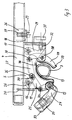
- each cross member 4 consists of one, in particular from FIG. 6 Housing 5 and a lever mechanism accommodated by the housing 5 6, which is shown particularly clearly in FIG. 7.
- the housing 5, which is composed of the housing parts 7, 8, has side walls 9, 10, a front end wall 11 and a rear End wall 12 on. That goes up and in certain areas forward and down open housing 5 is with material areas drawn inwards on the side walls provided that one another from above onto the Form gallery rod 3 supportable jaws 13.
- In the side walls 9, 10 of the housing 5 are bores 14 lying opposite one another provided for receiving bearing bolts 15, 16, 17 of the lever mechanism 6 serve.
- the housing 5 also has a right angle from the housing end wall 12 striving extension 18 with a bore 19 and in extension the end wall 11 a hammer head-like extension 20 with a neck 22 formed by side slots 21.
- the housing 5 is on the underside of the cross member 4, which has an axial end region has a longitudinal slot in its bottom wall.
- the process 18 is supported on the bottom wall of the cross member 4 and on the Grip longitudinal slot in the cross member 4 adjacent floor wall areas into the slots 21 on the extension 20.
- An axial definition of the housing 5 on the cross member 4 is carried out by a fastener, for. B. a screw 23 which can be screwed into a rivet nut 37.
- Within the cross member 4 is still a clamp angle 36.
- the lever mechanism 6 comprises an angle lever serving as a tensioning lever 24, an intermediate lever 25, a position lever 26, a tab 27, a pivotable jaw 28 and an adjusting lever 29.
- the angle lever 24 is pivotable about the bearing pin 15 fixed to the housing.
- the intermediate lever 25 is at one end a first bearing pin 30 articulated.
- the intermediate lever is different 25 on the one hand on the position lever 26, which is around the housing-fixed bearing pin 16 is pivotable, and on the other hand on the tab 27 at one end articulated, specifically via a second bearing pin 30.
- the tab 27 is with its other end region via a third bearing pin 30 articulated at the upper end of the approximately sickle-shaped clamping jaw 28, which in turn is approximately centered around a fourth bearing pin 30 is pivotable.
- the adjusting lever 29 is also on the fourth bearing pin 30 articulated at one end, the other end pivotable about the bearing pin 17 is.
- the first hinge pin 30 is on a circular arc ban pivoted about the bearing pin 15 so that the second hinge pin 30th pivoted on a circular arc around the bearing pin 16, whereby again the clamping jaw 28 via the tab 27 around the fourth hinge pin 30 is pivoted and clamped against the gallery bar 30.
- the short lever arm of the tensioning lever forms with the intermediate lever 25 likewise like the position lever 26 with the tab 27 each have a toggle lever, whose lever arms when clamping the gallery rod 3 from a strong angled position (Fig. 2 and 3) in a dead center position (Fig. 4) be stretched. An unwanted loosening of the fastening device is therefore not possible.
- the adjusting lever 28 In order to be able to tension gallery rods of different sizes, is for the adjusting lever 28 is provided with an actuator Set screw 31 exists.
- the set screw 31 sits with its threaded shaft in an internally threaded hole 32, which in the end wall 12 of the housing 5 is formed.
- the free end of the Set screw 31 acts on the adjusting lever 29, which is around the bearing pin 17 can pivot around. So you can effortlessly do that Set the required clamping dimension between the jaws 13 and 28.
- the angle lever 24 forming the tensioning lever is expediently included a handle shell 33 covering the front of the housing 5, that from a deep-drawn sheet metal body but also from a plastic injection molded part can exist. Between the angle lever 24 and the grip shell 33 there is a rigid connection.
- the grip shell 33 is with a lock cylinder 34 to be actuated by a key Lock bolt equipped.
- the individual levers of the lever mechanism advantageously consist of deformed sheet metal stampings, which makes it simple and inexpensive Manufacture of the fastening device is made possible.
- everyone Single lever preferably consists of two together via a web connected legs, which is particularly clear through FIGS. 5 and 7 is made clear.
- FIG. 8 shows, e.g. in comparison with Fig. 4, that the new quick release fastening device is definitely used on gallery bars 3 of different dimensions in cross section is. All that is required is to screw the Set screw 31 in the hole 32 required. A turning of the Set screw 31 away from adjusting lever 29 causes an enlargement of the clamping dimension while turning the adjusting screw 31 to the adjusting lever 29 results in a corresponding reduction in the clamping dimension.
- clamping jaws 13 and 28 can each be equipped with an abrasion protection device 38, 39 to avoid scratching the surface of the gallery bar.
Landscapes
- Engineering & Computer Science (AREA)
- General Engineering & Computer Science (AREA)
- Mechanical Engineering (AREA)
- Fittings On The Vehicle Exterior For Carrying Loads, And Devices For Holding Or Mounting Articles (AREA)
- Mutual Connection Of Rods And Tubes (AREA)
- Clamps And Clips (AREA)
Description
- Fig. 1
- eine auf einem Fahrzeugdach angeordnete Dachreling mit Querträgern,
- Fig. 2
- einen Endbereich eines Querträgers mit einer daran angeordneten Befestigungsvorrichtung im völlig geöffneten Zustand, aufgesetzt auf einen Galeriestab,
- Fig. 3
- die Befestigungsvorrichtung und ihre Anordnung nach Fig. 2, jedoch in einem halb geöffneten/geschlossenen Zustand,
- Fig. 4
- die Befestigungsvorrichtung und ihre Anordnung nach Fig. 2 oder 3, jedoch im völlig geschlossenen, gespannten Zustand,
- Fig. 5
- eine perspektivische Ansicht der Befestigungsvorrichtung mit nur teilweise dargestelltem Gehäuse,
- Fig. 6
- eine perspektivische Ansicht des Gehäuses der Befestigungsvorrichtung,
- Fig. 7
- eine perspektivische Ansicht der Hebelmechanik und
- Fig. 8
- die Befestigungsvorrichtung und ihre Anordnung ähnlich der nach Fig. 4, jedoch in einer gegenüber Fig. 4 abgewandelten Ausführungsform.
- 1
- Dachblech
- 2
- Stützfüße
- 3
- Galeriestäben
- 4
- Querträger
- 5
- Gehäuse
- 6
- Hebelmechanik
- 7
- Gehäuseteil
- 8
- Gehäuseteil
- 9
- Seitenwand
- 10
- Seitenwand
- 11
- Stirnwand vorne
- 12
- Stirnwand hinten
- 13
- Spannbacken
- 14
- Bohrungen
- 15
- Lagerbolzen
- 16
- Lagerbolzen
- 17
- Lagerbolzen
- 18
- Fortsatz
- 19
- Bohrung
- 20
- Fortsatz
- 21
- Schlitze
- 22
- Hals
- 23
- Schraube
- 24
- Winkelhebel
- 25
- Zwischenhebel
- 26
- Positionshebel
- 27
- Lasche
- 28
- Spannbacken
- 29
- Einstellhebel
- 30
- Lagerbolzen
- 31
- Stellschraube
- 32
- Lochdurchzug
- 33
- Griffschale
- 34
- Schließzylinder
- 35
- Langloch
- 36
- Klemmwinkel
- 37
- Nietmutter
- 38
- Scheuerschutzvorrichtung
- 39
- Scheuerschutzvorrichtung
Claims (7)
- Befestigungsvorrichtung, die einerseits an einem Querträger (4) und andererseits an einem Galeriestab (3) eines mit einer Dachreling ausgestatteten Kraftwagens anordbar ist miteinem am Querträger (4) befestigbaren Gehäuse (5), an dem ein fester von oben her auf den Galeriestab (3) abstützbarer Spannbacken (13) ausgebildet ist,zwei senkrecht orientierten und mit Abstand zueinander ausgerichteten Gehäusewänden (9, 10), zwischen denen eine Hebelmechanik (6) auf Gelenkbolzen (30) und gehäusefesten Lagerbolzen (15, 16, 17) angeordnet ist, undeiner Hebelmechanik (6) mit einem als Spannhebel dienenden, um einen gehäusefesten Lagerbolzen (15) schwenkbaren Winkelhebel (24), einem am kurzen Hebelarm desselben über einen Gelenkbolzen (30) angelenkten Zwischenhebel (25), der anderendig über einen Gelenkbolzen (30) einerseits an einem Positionshebel (26), der um einen gehäusefesten Lagerbolzen (16) schwenkbar ist, und andererseits an einer Lasche (27) angelenkt ist, die ihrerseits anderendig über einen Gelenkbolzen (30) einendig an einem etwa mittig um einen Gelenkbolzen (30) relativ zum oberen festen Spannbacken (13) schwenkbaren unteren Spannbacken (28) angelenkt ist, der über seinen etwa mittigen Lagerbolzen (30) mit einem Einstellhebel (29) verbunden ist, der um einen gehäusefesten Lagerbolzen (17) über ein Verstellelement schwenkbar ist.
- Befestigungsvorrichtung nach Anspruch 1, dadurch gekennzeichnet, daß der kurze Hebelarm des Spannhebels (24) mit dem Zwischennebel (25) und auch der Positionshebel (26) mit der Lasche (27) jeweils nach Art eines Kniehebels durch den jeweiligen Gelenkbolzen (30) miteinander verbunden sind, derart, daß sie beim Verschwenken des Spannhebels (24) in oder entgegen der Spannrichtung über die gestreckte Totpunktlage hinweg bewegbar sind.
- Befestigungsvorrichtung nach Anspruch 1 oder 2, dadurch gekennzeichnet, daß der Spannhebel (24) als Griffschale (33) ausgebildet oder mit einer solchen bestückt ist, wobei die Griffschale (33) einen mittels Schlüssel zu betätigenden Schließzylinder (34) mit Schließriegel als Diebstahlsicherung trägt.
- Befestigungsvorrichtung nach Anspruch 3, dadurch gekennzeichnet, daß die Griffschale (33) eine den Querträger (4) untergreifende Länge aufweist oder eine Länge, die einen stirnendigen Abschluß des Querträgers (4) ermöglicht.
- Befestigungsvorrichtung nach wenigstens einem der Ansprüche 1 bis 4, dadurch gekennzeichnet, daß die Lagerbohrung für den Gelenkbolzen (30) am positionshebelseitigen Ende des Zwischenhebels (25) als mit der Längsachse des Zwischenhebels (25) zusammenfallendes Langloch (35) ausgebildet ist.
- Befestigungsvorrichtung nach wenigstens einem der Ansprüche 1 bis 5, dadurch gekennzeichnet, daß das Gehäuse (5) an der Unterseite des Querträgers (4), der über einen axialen Endbereich einen Langsschlitz in seiner Bodenwand aufweist, befestigt ist und hierfür einendig einen gegenüber einer Gehäusestirnwand (12) rechtwinklig abstrebenden, sich an oder auf der Bodenwand des Querträgers (4) abstützenden Fortsatz (18) zum Festlegen am Querträger (4) mittels eines Befestigungselements, wie eine Schraube (23), und anderendig einen hammerkopfartigen Fortsatz (20) an der anderen Gehäusestirnwand (11) aufweist, dessen durch seitliche Schlitze (21) gebildeter Hals (22) in den Längsschlitz des Querträgers (4) einschiebbar ist.
- Befestigungsvorrichtung nach wenigstens einem der Ansprüche 1 bis 6, dadurch gekennzeichnet, daß der Einstellhebel (29) mittels einer in der ihm benachbarten Gehäusestirnwand (12) geführten Stellschraube (31) stufenlos auf das jeweilige Spannmaß einstellbar ist.
Applications Claiming Priority (2)
| Application Number | Priority Date | Filing Date | Title |
|---|---|---|---|
| DE4416339 | 1994-05-09 | ||
| DE4416339A DE4416339A1 (de) | 1994-05-09 | 1994-05-09 | Befestigungsvorrichtung |
Publications (2)
| Publication Number | Publication Date |
|---|---|
| EP0681943A1 EP0681943A1 (de) | 1995-11-15 |
| EP0681943B1 true EP0681943B1 (de) | 1998-09-16 |
Family
ID=6517684
Family Applications (1)
| Application Number | Title | Priority Date | Filing Date |
|---|---|---|---|
| EP95105437A Expired - Lifetime EP0681943B1 (de) | 1994-05-09 | 1995-04-11 | Befestigungsvorrichtung |
Country Status (3)
| Country | Link |
|---|---|
| US (1) | US5556221A (de) |
| EP (1) | EP0681943B1 (de) |
| DE (2) | DE4416339A1 (de) |
Families Citing this family (40)
| Publication number | Priority date | Publication date | Assignee | Title |
|---|---|---|---|---|
| US5730343A (en) * | 1996-01-12 | 1998-03-24 | Settelmayer; Joseph J. | Tower assembly for mounting a crossbar to a vehicle roof rack |
| US5845828A (en) * | 1996-01-12 | 1998-12-08 | Yakima Products | Tower assembly for mounting a crossbar to a vehicle roof rack |
| DE19713772A1 (de) * | 1997-04-03 | 1998-10-08 | Happich Fahrzeug Dachsysteme | Dachreling für Fahrzeuge |
| DE19734123A1 (de) * | 1997-08-07 | 1999-02-11 | Happich Fahrzeug Dachsysteme | Querträger für eine Kraftfahrzeug-Dachreling |
| SE510962C2 (sv) * | 1997-11-18 | 1999-07-12 | Thule Ind Ab | Fästanordning för lastbärarfot |
| JP3582394B2 (ja) * | 1998-12-09 | 2004-10-27 | トヨタ自動車株式会社 | ルーフキャリア取付構造 |
| US6155154A (en) * | 1999-03-20 | 2000-12-05 | Hsu; Yuan-Chang | Quick positioning device of a bank knife |
| DE19961713C1 (de) * | 1999-12-21 | 2001-09-27 | Daimler Chrysler Ag | Kraftfahrzeug mit Befestigungsstellen zur lösbaren Halterung wenigstens einer Trägereinheit |
| US6513626B2 (en) * | 2000-04-07 | 2003-02-04 | Macsweeney Terry | Releasably secure ladder platform |
| SE522882C2 (sv) * | 2000-12-21 | 2004-03-16 | Thule Ind Ab | Lastbärare för takreling |
| US6705051B1 (en) | 2001-03-02 | 2004-03-16 | Harlin J. Wall | Method of transporting prefabricated module with roof mounted in a horizontal position and apparatus for mounting the roof during transport |
| US6681971B2 (en) * | 2001-03-08 | 2004-01-27 | Thule Sweden Ab | Variably configurable securement arrangement in a load carrier |
| US6568644B2 (en) * | 2001-05-25 | 2003-05-27 | Jac Products Inc. | Clamp for a cross bar |
| US6793186B2 (en) * | 2001-05-25 | 2004-09-21 | Jac Products Inc. | Clamp for a cross bar |
| EP1340652B1 (de) * | 2002-02-28 | 2005-08-03 | Chiu-Kuei Wang | Verstellbare Dachträgervorrichtung für Fahrzeuge |
| US7503470B2 (en) * | 2003-01-28 | 2009-03-17 | Yakima Products, Inc. | Car top carrier |
| AU2003231688A1 (en) * | 2003-01-31 | 2004-08-19 | Roof Rack Industries Pty Ltd | Rail Bar Roof Rack |
| DE10307230A1 (de) * | 2003-02-14 | 2004-09-02 | Oris Fahrzeugteile Hans Riehle Gmbh | Dachlastenträger |
| WO2005114019A2 (en) * | 2004-05-18 | 2005-12-01 | Watermark Paddlesports, Inc. | Crossbar tower assembly for a vehicle rack |
| DE102004044834A1 (de) * | 2004-09-14 | 2006-03-30 | Oris Fahrzeugteile Hans Riehle Gmbh | Dachträger für Kraftfahrzeuge |
| FR2879536B3 (fr) | 2004-12-21 | 2007-04-06 | Scambia Ind Dev Ag | Dispositif de fixation pour fixer une barre transversale a une barre longitudinale d'une galerie de toit d'un vehicule automobile |
| ATE391637T1 (de) * | 2005-02-04 | 2008-04-15 | Thule Sweden Ab | Lastträger für feste dachreling |
| US20070039985A1 (en) * | 2005-08-19 | 2007-02-22 | Charles Warren | Roof rack concept for passenger vehicles, incorporating reconfigurable, multipurpose storage roof for improved aerodynamics and aesthetics |
| DE102005053178A1 (de) * | 2005-11-03 | 2007-05-16 | Scambia Ind Dev Ag | Dachträger |
| US8132701B2 (en) * | 2008-01-10 | 2012-03-13 | Thule Sweden Ab | Rail and clamp mounting system |
| AU2009262302A1 (en) * | 2008-06-23 | 2009-12-30 | Yakima Products, Inc. | Rack tower for securing crossbars on top of a vehicle |
| WO2012047452A1 (en) | 2010-10-05 | 2012-04-12 | Yakima Products, Inc. | Stabilized cargo box for a vehicle rack system |
| WO2014022437A2 (en) | 2012-07-30 | 2014-02-06 | Yakima Innovation Development Corporation | Carrier for a vehicle |
| GB201215539D0 (en) * | 2012-08-31 | 2012-10-17 | Hewson Peter G | Connection device |
| EP2905179B1 (de) * | 2014-02-07 | 2017-07-12 | Thule Sweden AB | Lastträgerfuß |
| US10040403B2 (en) | 2015-06-09 | 2018-08-07 | Yakima Products, Inc. | Crossbar clamp actuator |
| US10676037B2 (en) | 2015-09-22 | 2020-06-09 | Grip Racks LLC | Modular roof rack clamping system |
| CN108025679B (zh) * | 2015-09-22 | 2020-03-03 | 格里普拉克斯有限责任公司 | 模块化车顶行李架夹紧系统 |
| WO2017214066A1 (en) * | 2016-06-05 | 2017-12-14 | Yakima Products, Inc. | Fork-mount bicycle carrier |
| IT201700114809A1 (it) * | 2017-10-12 | 2019-04-12 | ATHANOR Srl | Dispositivo connettibile al portabagagli di un’autovettura per un rapido approntamento dello stesso al trasporto in sicurezza di uno o più colli, portabagagli comprendente detto dispositivo e autovettura dotata di un portabagagli comprendente detto dispositivo |
| US10375944B2 (en) | 2017-10-16 | 2019-08-13 | Trxstle, Llc | Convertible fishing rod carrier |
| US10723277B2 (en) * | 2018-01-31 | 2020-07-28 | Jac Products, Inc. | Vehicle article carrier system with end support having tunable clamping force |
| EP3552880B1 (de) * | 2018-04-11 | 2020-10-14 | Thule Sweden AB | Befestigungsvorrichtung für einen lastträger |
| US11325539B2 (en) | 2019-03-08 | 2022-05-10 | Yakima Products, Inc. | Fishing gear carrier box |
| US11673238B2 (en) * | 2020-02-12 | 2023-06-13 | The Boeing Company | Locking spanner assembly |
Family Cites Families (23)
| Publication number | Priority date | Publication date | Assignee | Title |
|---|---|---|---|---|
| DE8136129U1 (de) * | 1982-06-16 | Oris-Metallbau KG Hans Riehle, 7141 Möglingen | Querträger für Dachlasten an einem mit einer Dachreling ausgestatteten Kraftwagen | |
| DE8229914U1 (de) * | 1983-02-03 | Frey, Dieter, 8100 Garmisch-Partenkirchen | Querträger zur Befestigung an der Dachreling eines Kraftfahrzeuges | |
| DE8229446U1 (de) * | 1983-04-28 | Oris-Metallbau KG Hans Riehle, 7141 Möglingen | Stützfuß an einem Querträger, Grundbügel o.dgl. zur Befestigung an der Dachreling eines Kraftwagens | |
| DE690148C (de) * | 1939-02-19 | 1940-04-17 | Siemens Schuckertwerke Akt Ges | Anordnung an generatorisch arbeitenden Drehstrom-Rterregung mit netzfremder Frequenz |
| US2447199A (en) * | 1945-01-26 | 1948-08-17 | Edward F Miller | Toggle link operated hand clamp |
| DE2703719A1 (de) * | 1977-01-29 | 1978-08-03 | Daimler Benz Ag | An einem transportbehaelter, insbesondere koffer, vorgesehene befestigungseinrichtung fuer gepaecktraeger auf vorzugsweise daechern von fahrzeugen |
| DE2804588C2 (de) * | 1978-02-03 | 1983-11-17 | Daimler-Benz Ag, 7000 Stuttgart | Ein auf einer Dachreling eines Kraftfahrzeuges sich abstützender und aus Rohren bestehender Dachlastenträger für Transportbehälter, insbesondere Wechselaufbauten |
| SE432079B (sv) * | 1982-08-02 | 1984-03-19 | Tore Eklund | Lasthallare |
| IT8553029U1 (it) * | 1985-02-25 | 1986-08-25 | G E V Ricambi S P A | Portacarichi applicabile indistintamente ad autovetture con e senza gocciolatoi. |
| DE3510805A1 (de) * | 1985-03-25 | 1986-10-02 | Gebr. Haslbeck GmbH, 8260 Mühldorf | Klemmvorrichtung fuer dachtraegersysteme |
| DE3619673A1 (de) * | 1986-01-21 | 1987-07-23 | Wunder Gmbh Co Kg Heinrich | Einstellbarer tragbuegel fuer dachlastentraeger |
| DE3709335A1 (de) * | 1987-03-21 | 1988-10-06 | Opel Adam Ag | Dachgepaecktraeger fuer ein kraftfahrzeug |
| SU1539100A1 (ru) * | 1987-11-30 | 1990-01-30 | Предприятие П/Я Ю-9903 | Устройство дл креплени длинномерных изделий на кузове транспортного средства |
| WO1990002668A1 (en) * | 1988-09-09 | 1990-03-22 | Mont Blanc Industrie Ab | A joint structure in quick-fastening load-carrier supports |
| DE9015530U1 (de) * | 1989-11-17 | 1991-02-14 | Hagus C. Luchtenberg Gmbh & Co Kg, 5650 Solingen | Lastträger für ein Fahrzeug mit Dachreling |
| DE4001546A1 (de) * | 1990-01-20 | 1991-07-25 | Theodor Splithoff | Tragstrebenhalterung fuer kraftfahrzeuge |
| DE4108058C2 (de) * | 1991-03-13 | 1995-01-12 | Votex Gmbh | Dachgepäckträger für Kraftfahrzeuge mit Dachreling |
| DE4223899A1 (de) * | 1992-07-21 | 1994-01-27 | Happich Gmbh Gebr | Querholm für Dachgepäckträger von Kraftwagen mit Dachreling |
| DE4242207A1 (de) * | 1992-12-15 | 1994-06-16 | Happich Gmbh Gebr | Querträger für Dachlasten an einem mit einer Dachreling ausgestatteten Kraftwagen |
| DE4315024A1 (de) * | 1993-05-06 | 1994-11-10 | Happich Gmbh Gebr | Dachgepäckträger für Kraftfahrzeuge mit Dachreling |
| US5366128A (en) * | 1993-11-05 | 1994-11-22 | Yakima Products, Inc. | Crossbar support for vehicle roof rack |
| US5385285A (en) * | 1993-12-07 | 1995-01-31 | Jac Products, Inc. | Vehicle article carrier |
| DE9407580U1 (de) * | 1994-05-06 | 1994-08-11 | Linnhoff, Frank, 85051 Ingolstadt | Vorrichtung zum Festlegen eines Dachträgers an einer Reling |
-
1994
- 1994-05-09 DE DE4416339A patent/DE4416339A1/de not_active Withdrawn
-
1995
- 1995-04-11 DE DE59503575T patent/DE59503575D1/de not_active Expired - Fee Related
- 1995-04-11 EP EP95105437A patent/EP0681943B1/de not_active Expired - Lifetime
- 1995-04-14 US US08/423,007 patent/US5556221A/en not_active Expired - Fee Related
Also Published As
| Publication number | Publication date |
|---|---|
| EP0681943A1 (de) | 1995-11-15 |
| DE4416339A1 (de) | 1995-11-16 |
| US5556221A (en) | 1996-09-17 |
| DE59503575D1 (de) | 1998-10-22 |
Similar Documents
| Publication | Publication Date | Title |
|---|---|---|
| EP0681943A1 (de) | Befestigungsvorrichtung | |
| EP0566857B1 (de) | Vorrichtung zur Verriegelung von Zubehör oder Ausrüstungsgegenständen | |
| EP0647545B1 (de) | Querträger für Dachlasten an einem mit einer Dachreling ausgestatteten Kraftwagen | |
| DE3943715C2 (de) | Drehstangenverschluß | |
| DE4431372C2 (de) | Schnappschloß mit Ausklinkfunktion | |
| DE3726200C2 (de) | ||
| DE19715924A1 (de) | Fahrzeugträger | |
| DE69012108T2 (de) | Vorrichtung für lastträger. | |
| DE9417400U1 (de) | Vorrichtung zur Festlegung eines Kofferraumdeckels | |
| DE60103376T2 (de) | Biegevorrichtung, insbesondere für eine flache blechplatte | |
| DE68922953T2 (de) | Verriegelung mit Drehstange für Kraftfahrzeuge, Behälter o.dgl. | |
| DE19955289C2 (de) | Buchsenziehvorrichtung | |
| DE9407580U1 (de) | Vorrichtung zum Festlegen eines Dachträgers an einer Reling | |
| DE10036398A1 (de) | Vorrichtung zur Arretierung eines Schließzylindergehäuses | |
| DE60008696T2 (de) | Lastenträger für ein Kraftfahrzeug sowie Kraftfahrzeug mit einem Lastenträger | |
| DE10101084A1 (de) | Lastenträger zur lösbaren Montage an einem Fahrzeug | |
| DE19959940B4 (de) | Lastträgerfuß | |
| DE102005044132A1 (de) | Befestigungssystem mit Spannverschluss zum Befestigen eines Gepäckstücks auf einem Fahrradgepäckträger | |
| DE9104766U1 (de) | Antipaniktürschloß | |
| DE69104020T2 (de) | Scharnier, insbesondere für Flügel oder Haube von Kraftfahrzeugen. | |
| DE19708906B4 (de) | Verbesserungen an Lastenträgern | |
| DE3912989A1 (de) | Aufsatzteil fuer eine traegerstange einer aussen an einem kraftfahrzeug anzubringenden traegerkonstruktion | |
| DE19729064B4 (de) | Zusammenklappbarer Exzenterspannhebel | |
| DE29922064U1 (de) | Spanner zum Halten bzw. Spannen von Bauteilen | |
| DE20201533U1 (de) | Kraftfahrzeug mit mindestens einem Dachstab |
Legal Events
| Date | Code | Title | Description |
|---|---|---|---|
| PUAI | Public reference made under article 153(3) epc to a published international application that has entered the european phase |
Free format text: ORIGINAL CODE: 0009012 |
|
| 17P | Request for examination filed |
Effective date: 19950510 |
|
| AK | Designated contracting states |
Kind code of ref document: A1 Designated state(s): DE FR GB IT SE |
|
| GRAG | Despatch of communication of intention to grant |
Free format text: ORIGINAL CODE: EPIDOS AGRA |
|
| 17Q | First examination report despatched |
Effective date: 19971127 |
|
| GRAG | Despatch of communication of intention to grant |
Free format text: ORIGINAL CODE: EPIDOS AGRA |
|
| GRAH | Despatch of communication of intention to grant a patent |
Free format text: ORIGINAL CODE: EPIDOS IGRA |
|
| GRAH | Despatch of communication of intention to grant a patent |
Free format text: ORIGINAL CODE: EPIDOS IGRA |
|
| GRAA | (expected) grant |
Free format text: ORIGINAL CODE: 0009210 |
|
| AK | Designated contracting states |
Kind code of ref document: B1 Designated state(s): DE FR GB IT SE |
|
| PG25 | Lapsed in a contracting state [announced via postgrant information from national office to epo] |
Ref country code: IT Free format text: LAPSE BECAUSE OF FAILURE TO SUBMIT A TRANSLATION OF THE DESCRIPTION OR TO PAY THE FEE WITHIN THE PRE;WARNING: LAPSES OF ITALIAN PATENTS WITH EFFECTIVE DATE BEFORE 2007 MAY HAVE OCCURRED AT ANY TIME BEFORE 2007. THE CORRECT EFFECTIVE DATE MAY BE DIFFERENT FROM THE ONE RECORDED.SCRIBED TIME-LIMIT Effective date: 19980916 |
|
| REF | Corresponds to: |
Ref document number: 59503575 Country of ref document: DE Date of ref document: 19981022 |
|
| GBT | Gb: translation of ep patent filed (gb section 77(6)(a)/1977) |
Effective date: 19981014 |
|
| ET | Fr: translation filed | ||
| REG | Reference to a national code |
Ref country code: FR Ref legal event code: CD |
|
| PLBE | No opposition filed within time limit |
Free format text: ORIGINAL CODE: 0009261 |
|
| STAA | Information on the status of an ep patent application or granted ep patent |
Free format text: STATUS: NO OPPOSITION FILED WITHIN TIME LIMIT |
|
| 26N | No opposition filed | ||
| PGFP | Annual fee paid to national office [announced via postgrant information from national office to epo] |
Ref country code: FR Payment date: 20010312 Year of fee payment: 7 |
|
| PGFP | Annual fee paid to national office [announced via postgrant information from national office to epo] |
Ref country code: SE Payment date: 20010319 Year of fee payment: 7 Ref country code: GB Payment date: 20010319 Year of fee payment: 7 |
|
| PGFP | Annual fee paid to national office [announced via postgrant information from national office to epo] |
Ref country code: DE Payment date: 20010321 Year of fee payment: 7 |
|
| REG | Reference to a national code |
Ref country code: GB Ref legal event code: IF02 |
|
| PG25 | Lapsed in a contracting state [announced via postgrant information from national office to epo] |
Ref country code: GB Free format text: LAPSE BECAUSE OF NON-PAYMENT OF DUE FEES Effective date: 20020411 |
|
| PG25 | Lapsed in a contracting state [announced via postgrant information from national office to epo] |
Ref country code: SE Free format text: LAPSE BECAUSE OF NON-PAYMENT OF DUE FEES Effective date: 20020412 |
|
| PG25 | Lapsed in a contracting state [announced via postgrant information from national office to epo] |
Ref country code: DE Free format text: LAPSE BECAUSE OF NON-PAYMENT OF DUE FEES Effective date: 20021101 |
|
| EUG | Se: european patent has lapsed |
Ref document number: 95105437.8 |
|
| GBPC | Gb: european patent ceased through non-payment of renewal fee |
Effective date: 20020411 |
|
| PG25 | Lapsed in a contracting state [announced via postgrant information from national office to epo] |
Ref country code: FR Free format text: LAPSE BECAUSE OF NON-PAYMENT OF DUE FEES Effective date: 20021231 |
|
| REG | Reference to a national code |
Ref country code: FR Ref legal event code: ST |