EP1538332B1 - Eolienne - Google Patents
Eolienne Download PDFInfo
- Publication number
- EP1538332B1 EP1538332B1 EP04028311.1A EP04028311A EP1538332B1 EP 1538332 B1 EP1538332 B1 EP 1538332B1 EP 04028311 A EP04028311 A EP 04028311A EP 1538332 B1 EP1538332 B1 EP 1538332B1
- Authority
- EP
- European Patent Office
- Prior art keywords
- gear
- sun gear
- planetary
- transmission
- rotor shaft
- Prior art date
- Legal status (The legal status is an assumption and is not a legal conclusion. Google has not performed a legal analysis and makes no representation as to the accuracy of the status listed.)
- Expired - Lifetime
Links
Images
Classifications
-
- F—MECHANICAL ENGINEERING; LIGHTING; HEATING; WEAPONS; BLASTING
- F03—MACHINES OR ENGINES FOR LIQUIDS; WIND, SPRING, OR WEIGHT MOTORS; PRODUCING MECHANICAL POWER OR A REACTIVE PROPULSIVE THRUST, NOT OTHERWISE PROVIDED FOR
- F03D—WIND MOTORS
- F03D15/00—Transmission of mechanical power
-
- F—MECHANICAL ENGINEERING; LIGHTING; HEATING; WEAPONS; BLASTING
- F03—MACHINES OR ENGINES FOR LIQUIDS; WIND, SPRING, OR WEIGHT MOTORS; PRODUCING MECHANICAL POWER OR A REACTIVE PROPULSIVE THRUST, NOT OTHERWISE PROVIDED FOR
- F03D—WIND MOTORS
- F03D15/00—Transmission of mechanical power
- F03D15/10—Transmission of mechanical power using gearing not limited to rotary motion, e.g. with oscillating or reciprocating members
-
- F—MECHANICAL ENGINEERING; LIGHTING; HEATING; WEAPONS; BLASTING
- F05—INDEXING SCHEMES RELATING TO ENGINES OR PUMPS IN VARIOUS SUBCLASSES OF CLASSES F01-F04
- F05B—INDEXING SCHEME RELATING TO WIND, SPRING, WEIGHT, INERTIA OR LIKE MOTORS, TO MACHINES OR ENGINES FOR LIQUIDS COVERED BY SUBCLASSES F03B, F03D AND F03G
- F05B2260/00—Function
- F05B2260/40—Transmission of power
- F05B2260/403—Transmission of power through the shape of the drive components
- F05B2260/4031—Transmission of power through the shape of the drive components as in toothed gearing
- F05B2260/40311—Transmission of power through the shape of the drive components as in toothed gearing of the epicyclic, planetary or differential type
-
- F—MECHANICAL ENGINEERING; LIGHTING; HEATING; WEAPONS; BLASTING
- F16—ENGINEERING ELEMENTS AND UNITS; GENERAL MEASURES FOR PRODUCING AND MAINTAINING EFFECTIVE FUNCTIONING OF MACHINES OR INSTALLATIONS; THERMAL INSULATION IN GENERAL
- F16H—GEARING
- F16H57/00—General details of gearing
- F16H57/02—Gearboxes; Mounting gearing therein
- F16H57/023—Mounting or installation of gears or shafts in the gearboxes, e.g. methods or means for assembly
- F16H2057/0235—Mounting or installation of gears or shafts in the gearboxes, e.g. methods or means for assembly specially adapted to allow easy accessibility and repair
-
- F—MECHANICAL ENGINEERING; LIGHTING; HEATING; WEAPONS; BLASTING
- F16—ENGINEERING ELEMENTS AND UNITS; GENERAL MEASURES FOR PRODUCING AND MAINTAINING EFFECTIVE FUNCTIONING OF MACHINES OR INSTALLATIONS; THERMAL INSULATION IN GENERAL
- F16H—GEARING
- F16H57/00—General details of gearing
- F16H57/08—General details of gearing of gearings with members having orbital motion
-
- Y—GENERAL TAGGING OF NEW TECHNOLOGICAL DEVELOPMENTS; GENERAL TAGGING OF CROSS-SECTIONAL TECHNOLOGIES SPANNING OVER SEVERAL SECTIONS OF THE IPC; TECHNICAL SUBJECTS COVERED BY FORMER USPC CROSS-REFERENCE ART COLLECTIONS [XRACs] AND DIGESTS
- Y02—TECHNOLOGIES OR APPLICATIONS FOR MITIGATION OR ADAPTATION AGAINST CLIMATE CHANGE
- Y02E—REDUCTION OF GREENHOUSE GAS [GHG] EMISSIONS, RELATED TO ENERGY GENERATION, TRANSMISSION OR DISTRIBUTION
- Y02E10/00—Energy generation through renewable energy sources
- Y02E10/70—Wind energy
- Y02E10/72—Wind turbines with rotation axis in wind direction
Definitions
- the present invention relates to a wind energy plant with a rotor, which is coupled via a hollow rotor shaft with a gear, which is in driving connection with a generator.
- the transmission can be formed in one or more stages, wherein the transmission has at least one planetary stage.
- a planetary stage generally consists of a sun gear around which a plurality of planetary gears meshing with the sun gear are arranged, the planetary gears being mounted in a planet carrier.
- the sun gear, the planetary gears and parts of the planet carrier are surrounded by a ring gear, wherein the ring gear is formed so that it meshes with the planetary gears. According to the desired translation direction either the sun gear or the planet carrier or the ring gear is driven.
- the first stage of the transmission in generic wind turbines is designed as a planetary stage, the rotor with the Planetary gear or the ring gear of the planetary stage and the sun gear, depending on whether it is a one-stage or a multi-stage transmission is coupled to the generator or to the next stage of the transmission.
- the coupling of the rotor via the rotor shaft with the gear can be done for example via the planet carrier.
- the planet carrier is offset by means of the rotor in a rotary motion.
- the stored in the planet carrier planetary gears are rolled by the rotation of the planet carrier between the, in this case, fixed housing ring gear and the sun gear, whereby the sun gear also in a rotational movement and thus drives the next stage of the transmission.
- the ring gear is coupled to the rotor shaft or that the ring gear is fixedly arranged in a ring gear, which in turn is coupled to the rotor shaft.
- the torque is introduced via the ring gear / Hohlradisme in the transmission.
- the ring gear drives the planet wheels, which are mounted in the, in this case, housing-fixed planet carrier.
- the planet gears are in turn passed between the ring gear and the sun gear and thereby drive the sun gear.
- the sun gear in a wind turbine gearbox is the most heavily loaded gear member. At the same time it is due to its mounting position and possibly subsequent gear stages in case of damage only by a partial or even complete disassembly of the transmission to remove it, the disassembly of the transmission with considerable expenditure of time and high costs.
- From the DE 296 09 794 is a wind turbine known with a transmission having at least one planetary stage with a sun gear.
- the sun gear is formed as an axis protruding through the front panel of the machine frame.
- Object of the present invention is a wind turbine, in which the sun can be used in a simple, inexpensive and gentle manner in a transmission or pulled out again, without the gearbox has to be disassembled for it.
- the object is achieved with a wind turbine, which has the characterizing features of claim 1 and a device suitable for this wind turbine with the features of claim 9.
- the transmission is designed such that the sun gear of at least one planetary stage can be inserted into or pulled out of the planetary stage by the hollow rotor shaft, that is to say on the generator side facing away from the generator.
- the rotor shaft z. B. a 5 MW wind turbine is designed for weight reasons as a hollow shaft and has an outer diameter of 1.45 m and an inner diameter of about 0.70 in on the inner diameter of the rotor shaft of a 5 MW system is so large that, for example, a Person has the opportunity to "commit" the rotor shaft from the inside.
- the possibility of "committing" the rotor shaft from the inside is advantageously used to create a previously unknown accessibility to the transmission.
- the wind turbine is designed so that a separating device is provided, via which the sun gear from the rest of the transmission is separable, wherein is provided in a particularly preferred embodiment, that the separating device can be actuated from the rotor shaft.
- a connector such as a curved tooth coupling
- means must be provided to prevent axial movement of the sun gear.
- a connector such as a curved tooth coupling
- means must be provided to prevent axial movement of the sun gear.
- the sun gear for example, designed as a rod shaft output side of the sun gear having a connecting flange which is releasably connectable to the curved tooth coupling, for example via a flexible screw connection.
- the diameter of the connecting flange must be at least so large that the screw connection can be produced from the rotor shaft by means of a corresponding tool.
- the diameter of the connecting flange may not be greater than the diameter of the sun gear, so that the connecting flange is also removable via the access opening from the gearbox when removing the sun gear.
- This embodiment of the invention has the advantage that it is now possible to separate the sun gear starting from the rotor shaft from the transmission and to take it out or reinsert it and connect it to the transmission. Cumbersome dismantling work such as in the worst case, a partial disassembly of the transmission are no longer required.
- the access to the transmission is designed, for example, such that the transmission has an access opening.
- the arrangement and size of the access opening in the transmission can be arbitrary, it only has to be chosen so that access from the rotor shaft to the sun gear is possible. However, it is advisable, according to an advantageous embodiment of the invention, the access opening centrally aligned with the sun gear.
- the first stage of the transmission is a planetary stage whose planet carrier is coupled to the hollow rotor shaft.
- the planet carrier may for example be designed so that it has a flange on its side facing the rotor shaft, which is coupled to the rotor shaft, wherein the inner diameter of the flange advantageously corresponds to at least the inner diameter of the hollow rotor shaft. It would also be conceivable, however, if the spatial dimensions in the wind turbine allow to choose the inner diameter larger, in order to allow the largest possible working range for work in relation to the sun gear. It is also conceivable that the rotor shaft and the planet carrier are integrally formed as a component.
- the planet carrier has the provided in the transmission access opening to the sun gear. This can be arranged, for example, at the foot of the flange, centric to the sun gear.
- the ring gear is formed so that it is coupled to the rotor shaft or that the ring gear disposed in a ring gear, which is then coupled to the rotor shaft and the access opening is arranged in accordance with the ring gear and / or Hohlradong ,
- the transmission has at least one further access opening which allows access to a planetary gear.
- This embodiment has the advantage that a planetary gear for repair and maintenance purposes also removed in a simple manner and can be used again.
- At least one of the access openings is formed lockable.
- the feature prevents that the lubricant necessary for the safe operation of the transmission can not pass through the access opening from the transmission into the hollow rotor shaft and can lead to contamination there.
- the lid is fastened, for example by screws to the planet carrier.
- the present invention therefore further comprises a device which is adapted to be arranged in the rotor shaft in front of the gearbox, a coupling device, which in a force-transmitting engagement with the Sun wheel can be brought such that the sun can be pulled out of the transmission or can be used in the transmission, wherein the device is designed so that the sun can be held by the device.
- the device according to the invention has the advantage that a person, for example, for repair purposes, no longer has to remove the sun gear manually, but instead the device is used for this purpose.
- the device may comprise an adjusting device, via which the sun gear located in force engagement with the coupling device can be pulled out of the transmission or can be used in the transmission.
- the device has a locking device, by means of which the device in the rotor shaft in front of the transmission can be arranged fixed in order to prevent a movement of the device during the removal of the sun gear.
- the device according to a further embodiment of the invention may comprise means for adjusting, with which the position of the device as a whole and / or the positions of individual devices of the device can be aligned to the transmission.
- a precise alignment of the device to the transmission, in particular to the sun gear has the advantage that the removal of the sun gear is simplified by the provision of adjusting means, as in this way the possibility of tilting the sun gear can be minimized when removing.
- means for adjusting can be provided, via which only the position of the device can be aligned to the transmission, wherein the means can be designed so that a positional alignment of the device to all axes, both translational and rotational is possible.
- adjustment means may also be provided for aligning, by means of which the position of individual devices of the device can be aligned to the transmission, whereby these means can also be designed so that a position alignment to all axes is possible.
- an alignment can take place both via the means for adjusting the device and via the means for adjusting individual devices of the device. For example, via the means for adjusting the device, a coarse adjustment and via the means for adjusting the devices, a subsequent fine adjustment, or vice versa.
- the individual components are correspondingly heavy, as well as the sun.
- a sun gear weighs approximately 80 kg. Accordingly, it is very difficult for a single person to remove such a sun gear from the wind turbine through the rotor shaft.
- the device additionally has a transport device for transporting the sun gear to an externally accessible area in the rotor shaft.
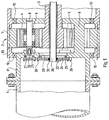
- FIG. 1 shows a sectional view of the coupling region of a rotor shaft with a first stage of a multi-stage transmission in a wind turbine.
- the other, not shown, end of the rotor shaft 1 is coupled to a rotor which is displaceable by wind energy in a rotational movement.
- the drive torque generated via the rotor is introduced via the rotor shaft 1 in the transmission.
- the first stage of the transmission is a planetary stage 2.
- the planetary stage 2 consists essentially of the following components: a sun gear 3, planet wheels 4, 5, a planet carrier 6 and a ring gear 7.
- the coupling of the rotor shaft 1 with the planetary stage 2 takes place in the illustrated embodiment via the planet 6.
- the planet carrier 6 has on its rotor side a flange 6 ', which allows connection to the rotor shaft, wherein it is a screw connection in the illustrated connection form is.
- the planet gears 4, 5 are mounted, which have an outer ring gear.
- the planet gears 4, 5 are arranged around a sun gear 3, wherein the sun gear 3 also has an external toothing, which meshes with the external toothing of the planetary gears.
- the bearing of the planet gears 4, 5 takes place in the planet carrier 6 via planet pins 8 and four bearings 9, wherein the planet pins 8 are arranged fixed to the housing in the planet 6.
- the bearings 9 may, for example, be ball bearings or bearings, but it would also be possible to use plain bearings.
- the ring gear 7 is fixed to the housing in a gear housing 33, wherein the ring gear 7 is formed so that it has an internal toothing, which also meshes with the external toothing of the planet wheels 4, 5.
- the planet carrier 6 is further mounted fixed to the housing through bearings 10.
- the planetary gear carrier 6 is set in rotary motion via the red-wave 1. Due to the housing-fixed mounting of the planet pins 8 in the planet 6, the planetary gears 4, 5 are rolled between the fixed housing ring gear 7 and the sun gear 3, whereby the sun gear 3, also in a rotational movement is added. From the sun gear 3 centered between the planet gears 4, 5, the generated torque is then transmitted to the next stage of the transmission.
- a cable tube 30 is centrally arranged in the transmission, through which the electrical lines are guided from the interior of the wind turbine to the rotor.
- the planet carrier 6 In order to remove the sun gear from the planetary stage for maintenance or repair purposes and to be able to use again, the planet carrier 6 has an access opening 20.
- the access opening 20 is centered to the sun gear 3 aligned and their dimensions are selected so that the sun gear 3 can be pulled out or used via this access opening 20 from the planetary stage 2.
- the planet carrier 6 may also have a second access opening 21 or, depending on the number of planet wheels, further access openings, wherein the further access openings may be arranged and configured such that the planetary gears 4, 5 are also removed from the planetary stage 2 in a simple manner can be used again.
- the access opening 21 is arranged and configured to allow the planetary pin 8 to be withdrawn from the planet carrier, for example with a puller engaging the threaded hole 32, not shown. After the sun gear and the planetary pin 8 have been taken out of the planetary stage 2, the planetary gear 4 can also be taken out of the planetary stage via the access opening 20.
- the access openings 20, 21 are closed with lids 22, 23 in the illustrated embodiment.
- the cover 22, 23 consist of a circular cover plate having a shoulder 25 on one side, which projects into the access opening 21 in the closed state.
- the heel can be designed so that it can be positively inserted into the access opening. But it is also conceivable that in the paragraph, a groove can be provided, in which a seal is used.
- the cover 22 also has an opening through which the cable tube 30 is led out of the transmission, wherein in the illustrated embodiment, the cable tube rotates with the transmission.
- the cover 22, 23 may consist in the simplest case only of a cover plate whose dimensions are chosen so that the access openings 20, 21 are closed with it.
- a seal may additionally be provided between the plate and the planet carrier 6. It would also be conceivable to additionally incorporate a groove in the cover plate, in which the seal can be used.
- the attachment of the lid 22, 23 on the planet 6 can be done in different ways. In the illustrated embodiment, the attachment between the covers 22, 23 and the planet carrier 6 via screws 26.
- the attachment of the lid 22, 23 could, for example, but also be done by clamping handles. It would also be conceivable to provide on the cover 22, 23 and / or on the planet carrier 6 connecting devices which generate a firm connection when inserting the lid, for example by snapping. This would have the advantage that only a few steps are required for the insertion of the lid. In this context, it would also be conceivable to connect the cover via hinges with the planet carrier.
- the not shown also covered by the invention device for removing or inserting the sun gear may be formed, for example, as a car, which is driven by the rotor shaft to the transmission.
- On the carriage and on the planet carrier locking means may be provided to arrange the carriage in the coupling area to stationary.
- a coupling device may be provided on the carriage to connect the carriage to the sun gear.
- the coupling device may in its simplest embodiment, for example, have threaded rods, which must be dimensioned accordingly in order to bear the weight of the sun gear can.
- the threaded rods can be screwed into provided in the sun gear tapped holes.
- the wheels of the car can be designed to be height adjustable.
- the coupling device could be designed so that it is designed to be adjustable with respect to its rotational axes.
- the adjusting device of the device may, for example, have rails on which the coupling device can be arranged guided, wherein the rails are arranged axially to the sun gear on the carriage.
- the coupling device is arranged in the front, geared to the area of the car. After the carriage and the sun gear have been connected to each other via the threaded rods, the sun gear is pulled out of the gearbox onto the carriage by retracting the coupling device carried on the rails. Subsequently, the now arranged on the carriage sun gear can be pushed through the rotor shaft, for example, to the rotor to maintain or replace the sun gear in the rotor.
- the adjusting device may additionally also have means by which the sun gear can be unscrewed from the transmission when pulling out according to the helical toothing.
- the planetary gears can be removed by means of the device from the planetary stage.
- a lifter could be inserted into the transmission via the access port 20 which is extendable to the planetary gear. Subsequently, the planetary pin is removed, retracted the lifting device and pulled out the planetary gear from the transmission.
Landscapes
- Engineering & Computer Science (AREA)
- Life Sciences & Earth Sciences (AREA)
- Sustainable Development (AREA)
- Sustainable Energy (AREA)
- Chemical & Material Sciences (AREA)
- Combustion & Propulsion (AREA)
- Mechanical Engineering (AREA)
- General Engineering & Computer Science (AREA)
- Retarders (AREA)
- Wind Motors (AREA)
Claims (8)
- Éolienne avec un rotor, un engrenage, qui est couplé avec le rotor par l'intermédiaire d'un arbre de rotor creux (1), ainsi qu'un générateur qui est en liaison d'entraînement avec l'engrenage, l'engrenage comprenant au moins un étage conçu comme un étage planétaire (2), qui comprend essentiellement une roue solaire (3), au moins une roue planétaire (4, 5), un support de roue planétaire (6) et une roue à denture intérieure (7), l'engrenage étant conçu de façon à ce que la roue solaire (3) d'au moins un étage planétaire (2) puisse être insérée dans l'étage planétaire (2) à travers l'arbre de rotor creux (1) ou puisse être retirée de celui-ci, l'engrenage comprenant une ouverture d'accès (20) qui permet un accès de l'arbre de rotor (1) à la roue solaire et dont les dimensions sont choisies de façon à ce que la roue solaire puisse être retirée ou insérée dans l'étage planétaire par cette ouverture d'accès, caractérisée en ce que l'ouverture d'accès (20, 21) est conçue de manière refermable avec un couvercle.
- Éolienne selon la revendication 1, caractérisée en ce que la roue solaire (3) peut être séparée du reste de l'engrenage ou du générateur par un dispositif de séparation.
- Éolienne selon la revendication 2, caractérisée en ce que le dispositif de séparation est conçu de façon à ce qu'il puisse être commandé à partir de l'arbre de rotor (1).
- Éolienne selon la revendication 1, caractérisée en ce que l'ouverture d'accès (20) est orientée de manière centrale par rapport à la roue solaire.
- Éolienne selon l'une des revendications précédentes, caractérisée en ce que l'engrenage comprend plusieurs étages dont le premier étage de l'engrenage est conçu comme un étage planétaire (2), dont le support de roue planétaire (6) est couplé avec l'arbre de rotor creux (1).
- Éolienne selon la revendication 5, caractérisée en ce que le support de roue planétaire (6) comprend l'ouverture d'accès (20) prévue dans l'engrenage.
- Éolienne selon la revendication 1, caractérisée en ce que l'engrenage comprend au moins une ouverture d'accès supplémentaire (21) qui permet un accès à une roue planétaire (4).
- Éolienne selon l'une des revendications précédentes, caractérisée en ce que la fermeture de l'ouverture d'accès (20, 21) a lieu par l'intermédiaire d'un couvercle (22, 23).
Applications Claiming Priority (2)
| Application Number | Priority Date | Filing Date | Title |
|---|---|---|---|
| DE10357026 | 2003-12-03 | ||
| DE10357026A DE10357026B3 (de) | 2003-12-03 | 2003-12-03 | Windenergieanlage |
Publications (3)
| Publication Number | Publication Date |
|---|---|
| EP1538332A2 EP1538332A2 (fr) | 2005-06-08 |
| EP1538332A3 EP1538332A3 (fr) | 2011-05-18 |
| EP1538332B1 true EP1538332B1 (fr) | 2016-08-03 |
Family
ID=34442477
Family Applications (1)
| Application Number | Title | Priority Date | Filing Date |
|---|---|---|---|
| EP04028311.1A Expired - Lifetime EP1538332B1 (fr) | 2003-12-03 | 2004-11-30 | Eolienne |
Country Status (4)
| Country | Link |
|---|---|
| EP (1) | EP1538332B1 (fr) |
| DE (1) | DE10357026B3 (fr) |
| DK (1) | DK1538332T3 (fr) |
| ES (1) | ES2599528T3 (fr) |
Families Citing this family (23)
| Publication number | Priority date | Publication date | Assignee | Title |
|---|---|---|---|---|
| DE102007033806B4 (de) | 2007-07-17 | 2011-03-17 | Nordex Energy Gmbh | Getriebe für eine Windenergieanlage |
| DE102007037542B4 (de) | 2007-08-09 | 2017-08-03 | Nordex Energy Gmbh | Windenergieanlagengetriebe mit einer Inspektionsöffnung |
| WO2009052824A2 (fr) * | 2007-10-22 | 2009-04-30 | Vestas Wind Systems A/S | Étage de train épicycloïdal pour boîte d'éolienne, boîte de vitesse d'éolienne et éolienne |
| BE1017866A3 (nl) * | 2007-12-06 | 2009-09-01 | Hansen Transmissions Int | Windturbineaandrijving. |
| DE102007060985A1 (de) * | 2007-12-14 | 2009-06-18 | Innovative Windpower Ag | Vorrichtung zur Übertragung von Bereitstellungsmitteln |
| DK2072863T3 (da) | 2007-12-19 | 2012-07-30 | Zf Wind Power Antwerpen Nv | Planetbærer til en planetramme med en bogieplade |
| DE102008022383B4 (de) | 2008-05-06 | 2016-01-21 | Senvion Gmbh | Positionierung eines Rotors einer Windenergieanlage |
| DE102008033066B4 (de) | 2008-07-15 | 2014-03-27 | Repower Systems Se | Demontage eines Getriebes einer Windenergieanlage |
| DK200801525A (da) * | 2008-11-06 | 2009-11-05 | Lm Glasfiber As | Fremgangsmåde til udfyldning af et tværsnit |
| DE102009017521B4 (de) | 2009-04-17 | 2011-04-28 | Repower Systems Ag | Getriebe einer Windenergieanlage |
| DE102009032667A1 (de) | 2009-07-09 | 2011-01-13 | Repower Systems Ag | Getriebe einer Windenergieanlage |
| EP2388498B1 (fr) * | 2010-05-21 | 2012-09-19 | Winergy AG | Transmission pour une éolienne |
| DE102010040654A1 (de) | 2010-09-13 | 2012-03-15 | Repower Systems Se | Demontage eines Getriebes einer Windenergieanlage |
| US8734105B2 (en) | 2010-09-16 | 2014-05-27 | Vestas Wind Systems A/S | Control system for a wind turbine and method of operating a wind turbine based on monitoring a bearing |
| US8079761B1 (en) | 2010-09-16 | 2011-12-20 | Vestas Wind Systems A/S | Cylindrical plain bearing pocket arrangement and wind turbine having such a cylindrical plain bearing |
| US8727728B2 (en) | 2010-09-16 | 2014-05-20 | Vestas Wind Systems A/S | Convertible bearing for a wind turbine and method for operating same |
| WO2013042251A1 (fr) | 2011-09-22 | 2013-03-28 | 三菱重工業株式会社 | Dispositif générateur d'énergie à énergie récupérée, et procédé de montage/démontage d'une voilure tournante pour ce dispositif |
| US8172531B2 (en) | 2011-01-10 | 2012-05-08 | Vestas Wind Systems A/S | Plain bearing for a wind turbine blade and method of operating a wind turbine having such a plain bearing |
| CN104565306B (zh) * | 2013-10-17 | 2017-05-10 | 三江瓦力特特种车辆有限公司 | 可进行滑道润滑的行星排 |
| GB2543249B (en) * | 2015-08-12 | 2019-07-31 | Romax Tech Limited | Gearbox assembly |
| DE102015223669B4 (de) | 2015-11-30 | 2023-09-21 | Zf Friedrichshafen Ag | Planetengetriebe für eine Windkraftanlage und Verfahren zur Montage des Planetengetriebes |
| EP3379107B1 (fr) * | 2017-03-23 | 2020-11-25 | Cascade Drives AB | Dispositif d'engrenage planétaire composé et agencement de roue d'engrenage |
| CN113915319B (zh) * | 2021-10-28 | 2024-02-02 | 中船海装风电有限公司 | 风力发电机组增速齿轮箱 |
Citations (3)
| Publication number | Priority date | Publication date | Assignee | Title |
|---|---|---|---|---|
| WO1996011338A1 (fr) | 1994-10-07 | 1996-04-18 | Gerald Hehenberger | Engrenage planetaire pour turbine eolienne |
| DE29609794U1 (de) | 1996-06-03 | 1996-08-22 | aerodyn GmbH, 24768 Rendsburg | Getriebe-Generator-Kombination |
| US5663600A (en) | 1995-03-03 | 1997-09-02 | General Electric Company | Variable speed wind turbine with radially oriented gear drive |
Family Cites Families (4)
| Publication number | Priority date | Publication date | Assignee | Title |
|---|---|---|---|---|
| JPH0512505Y2 (fr) * | 1987-06-04 | 1993-03-31 | ||
| AT403310B (de) * | 1994-11-23 | 1998-01-26 | Hehenberger Gerald Dipl Ing | Planetengetriebe, insbesondere für windkraftanlagen |
| DE10043593B4 (de) * | 2000-09-01 | 2014-01-09 | Renk Ag | Getriebe für Windgeneratoren |
| DE10114609A1 (de) * | 2001-03-23 | 2002-09-26 | Enron Wind Gmbh | Drehmomentübertragungsvorrichtung für eine Windkraftanlage |
-
2003
- 2003-12-03 DE DE10357026A patent/DE10357026B3/de not_active Expired - Fee Related
-
2004
- 2004-11-30 EP EP04028311.1A patent/EP1538332B1/fr not_active Expired - Lifetime
- 2004-11-30 DK DK04028311.1T patent/DK1538332T3/en active
- 2004-11-30 ES ES04028311.1T patent/ES2599528T3/es not_active Expired - Lifetime
Patent Citations (3)
| Publication number | Priority date | Publication date | Assignee | Title |
|---|---|---|---|---|
| WO1996011338A1 (fr) | 1994-10-07 | 1996-04-18 | Gerald Hehenberger | Engrenage planetaire pour turbine eolienne |
| US5663600A (en) | 1995-03-03 | 1997-09-02 | General Electric Company | Variable speed wind turbine with radially oriented gear drive |
| DE29609794U1 (de) | 1996-06-03 | 1996-08-22 | aerodyn GmbH, 24768 Rendsburg | Getriebe-Generator-Kombination |
Also Published As
| Publication number | Publication date |
|---|---|
| DK1538332T3 (en) | 2016-11-28 |
| EP1538332A3 (fr) | 2011-05-18 |
| DE10357026B3 (de) | 2005-06-09 |
| ES2599528T3 (es) | 2017-02-02 |
| EP1538332A2 (fr) | 2005-06-08 |
Similar Documents
| Publication | Publication Date | Title |
|---|---|---|
| DE10357026B3 (de) | Windenergieanlage | |
| EP1659286B1 (fr) | Vireur pour axe de générateur entraîné par une éolienne | |
| EP3117099B1 (fr) | Système de couplage modulaire d'une transmission pour éoliennes comprenant un générateur | |
| EP1677032B1 (fr) | Méthode pour remplacer les satellites et boulon de montage | |
| DE102015119173B4 (de) | Planetengetriebe sowie Verfahren zur Wartung eines Planetengetriebes | |
| WO2010076120A1 (fr) | Mélangeur doté d'un récipient de mélange rotatif | |
| DE102009023079A1 (de) | Rundschalttisch | |
| EP2154367B1 (fr) | Procédé de montage d'un moyeu d'hélice sur un arbre de rotor d'une éolienne et éolienne | |
| EP2616714A1 (fr) | Démontage d'une transmission d'une installation d'éolienne | |
| DE19616704A1 (de) | Antriebsvorrichtung für eine Sattelstütze oder dergleichen | |
| EP3542057A1 (fr) | Transmission pour une éolienne | |
| DE102011079555B4 (de) | Antriebsanordnung für eine Vertikal-Rollenmühle | |
| DE3143148A1 (de) | Drehmomentwerkzeug | |
| DE202007018565U1 (de) | Windenergieanlage | |
| DE102010005538A1 (de) | Windenergieanlage mit einem oder mehreren Rotorblättern | |
| DE1800790A1 (de) | Antriebsvorrichtung fuer Regelstaebe von Kernreaktoren | |
| DE102022202383A1 (de) | Achsgetriebesystem für eine Kraftfahrzeugantriebsachse | |
| EP3104503A1 (fr) | Entrainement rotatif sans jeu | |
| DE102014005415B4 (de) | Lageranordnung für ein Getriebe und Verfahren zum Einstellen der Vorspannung einer Lageranordnung | |
| EP1566238B1 (fr) | Système électrique de mouvement linéaire avec un accouplement direct entre un système vis-écrou et un module moteur | |
| WO2019234179A1 (fr) | Éolienne | |
| DE102014008966A1 (de) | Antriebsanordnung für eine Vertikal-Rollenmühle | |
| EP3242013A1 (fr) | Éolienne comprenant un dispositif destine a faire tourner une nacelle de l'eolienne et procede de montage d'un dispositif destine a faire tourner une nacelle | |
| DE102008038069A1 (de) | Getriebe mit Leistungsverzweigung | |
| DE102005062168A1 (de) | Antriebseinrichtung für eine Umformmaschine, insbesondere Pressenantrieb, sowie Umformmaschine |
Legal Events
| Date | Code | Title | Description |
|---|---|---|---|
| PUAI | Public reference made under article 153(3) epc to a published international application that has entered the european phase |
Free format text: ORIGINAL CODE: 0009012 |
|
| AK | Designated contracting states |
Kind code of ref document: A2 Designated state(s): AT BE BG CH CY CZ DE DK EE ES FI FR GB GR HU IE IS IT LI LU MC NL PL PT RO SE SI SK TR |
|
| AX | Request for extension of the european patent |
Extension state: AL HR LT LV MK YU |
|
| PUAL | Search report despatched |
Free format text: ORIGINAL CODE: 0009013 |
|
| AK | Designated contracting states |
Kind code of ref document: A3 Designated state(s): AT BE BG CH CY CZ DE DK EE ES FI FR GB GR HU IE IS IT LI LU MC NL PL PT RO SE SI SK TR |
|
| AX | Request for extension of the european patent |
Extension state: AL HR LT LV MK YU |
|
| 17P | Request for examination filed |
Effective date: 20110621 |
|
| AKX | Designation fees paid |
Designated state(s): AT BE BG CH CY CZ DE DK EE ES FI FR GB GR HU IE IS IT LI LU MC NL PL PT RO SE SI SK TR |
|
| 17Q | First examination report despatched |
Effective date: 20120329 |
|
| RAP1 | Party data changed (applicant data changed or rights of an application transferred) |
Owner name: REPOWER SYSTEMS SE |
|
| RAP1 | Party data changed (applicant data changed or rights of an application transferred) |
Owner name: SENVION SE |
|
| RAP1 | Party data changed (applicant data changed or rights of an application transferred) |
Owner name: SENVION GMBH |
|
| RIC1 | Information provided on ipc code assigned before grant |
Ipc: F16H 57/023 20120101ALI20151124BHEP Ipc: F03D 11/02 20060101AFI20151124BHEP Ipc: F16H 57/08 20060101ALI20151124BHEP |
|
| REG | Reference to a national code |
Ref country code: DE Ref legal event code: R079 Ref document number: 502004015265 Country of ref document: DE Free format text: PREVIOUS MAIN CLASS: F03D0011020000 Ipc: F16H0057080000 |
|
| GRAP | Despatch of communication of intention to grant a patent |
Free format text: ORIGINAL CODE: EPIDOSNIGR1 |
|
| RIC1 | Information provided on ipc code assigned before grant |
Ipc: F16H 57/08 20060101AFI20160201BHEP Ipc: F03D 15/00 20160101ALI20160201BHEP Ipc: F16H 57/023 20120101ALI20160201BHEP |
|
| INTG | Intention to grant announced |
Effective date: 20160217 |
|
| GRAS | Grant fee paid |
Free format text: ORIGINAL CODE: EPIDOSNIGR3 |
|
| GRAA | (expected) grant |
Free format text: ORIGINAL CODE: 0009210 |
|
| AK | Designated contracting states |
Kind code of ref document: B1 Designated state(s): AT BE BG CH CY CZ DE DK EE ES FI FR GB GR HU IE IS IT LI LU MC NL PL PT RO SE SI SK TR |
|
| REG | Reference to a national code |
Ref country code: DE Ref legal event code: R081 Ref document number: 502004015265 Country of ref document: DE Owner name: SIEMENS GAMESA RENEWABLE ENERGY SERVICE GMBH, DE Free format text: FORMER OWNER: REPOWER SYSTEMS AG, 22297 HAMBURG, DE Ref country code: GB Ref legal event code: FG4D Free format text: NOT ENGLISH |
|
| REG | Reference to a national code |
Ref country code: CH Ref legal event code: EP Ref country code: AT Ref legal event code: REF Ref document number: 817550 Country of ref document: AT Kind code of ref document: T Effective date: 20160815 |
|
| REG | Reference to a national code |
Ref country code: IE Ref legal event code: FG4D Free format text: LANGUAGE OF EP DOCUMENT: GERMAN |
|
| REG | Reference to a national code |
Ref country code: DE Ref legal event code: R096 Ref document number: 502004015265 Country of ref document: DE |
|
| REG | Reference to a national code |
Ref country code: FR Ref legal event code: PLFP Year of fee payment: 13 |
|
| REG | Reference to a national code |
Ref country code: DK Ref legal event code: T3 Effective date: 20161122 |
|
| REG | Reference to a national code |
Ref country code: NL Ref legal event code: MP Effective date: 20160803 |
|
| PG25 | Lapsed in a contracting state [announced via postgrant information from national office to epo] |
Ref country code: NL Free format text: LAPSE BECAUSE OF FAILURE TO SUBMIT A TRANSLATION OF THE DESCRIPTION OR TO PAY THE FEE WITHIN THE PRESCRIBED TIME-LIMIT Effective date: 20160803 Ref country code: IS Free format text: LAPSE BECAUSE OF FAILURE TO SUBMIT A TRANSLATION OF THE DESCRIPTION OR TO PAY THE FEE WITHIN THE PRESCRIBED TIME-LIMIT Effective date: 20161203 Ref country code: FI Free format text: LAPSE BECAUSE OF FAILURE TO SUBMIT A TRANSLATION OF THE DESCRIPTION OR TO PAY THE FEE WITHIN THE PRESCRIBED TIME-LIMIT Effective date: 20160803 Ref country code: IT Free format text: LAPSE BECAUSE OF FAILURE TO SUBMIT A TRANSLATION OF THE DESCRIPTION OR TO PAY THE FEE WITHIN THE PRESCRIBED TIME-LIMIT Effective date: 20160803 |
|
| REG | Reference to a national code |
Ref country code: ES Ref legal event code: FG2A Ref document number: 2599528 Country of ref document: ES Kind code of ref document: T3 Effective date: 20170202 |
|
| PG25 | Lapsed in a contracting state [announced via postgrant information from national office to epo] |
Ref country code: PL Free format text: LAPSE BECAUSE OF FAILURE TO SUBMIT A TRANSLATION OF THE DESCRIPTION OR TO PAY THE FEE WITHIN THE PRESCRIBED TIME-LIMIT Effective date: 20160803 Ref country code: SE Free format text: LAPSE BECAUSE OF FAILURE TO SUBMIT A TRANSLATION OF THE DESCRIPTION OR TO PAY THE FEE WITHIN THE PRESCRIBED TIME-LIMIT Effective date: 20160803 Ref country code: PT Free format text: LAPSE BECAUSE OF FAILURE TO SUBMIT A TRANSLATION OF THE DESCRIPTION OR TO PAY THE FEE WITHIN THE PRESCRIBED TIME-LIMIT Effective date: 20161205 Ref country code: BE Free format text: LAPSE BECAUSE OF NON-PAYMENT OF DUE FEES Effective date: 20161130 Ref country code: GR Free format text: LAPSE BECAUSE OF FAILURE TO SUBMIT A TRANSLATION OF THE DESCRIPTION OR TO PAY THE FEE WITHIN THE PRESCRIBED TIME-LIMIT Effective date: 20161104 |
|
| PG25 | Lapsed in a contracting state [announced via postgrant information from national office to epo] |
Ref country code: EE Free format text: LAPSE BECAUSE OF FAILURE TO SUBMIT A TRANSLATION OF THE DESCRIPTION OR TO PAY THE FEE WITHIN THE PRESCRIBED TIME-LIMIT Effective date: 20160803 Ref country code: RO Free format text: LAPSE BECAUSE OF FAILURE TO SUBMIT A TRANSLATION OF THE DESCRIPTION OR TO PAY THE FEE WITHIN THE PRESCRIBED TIME-LIMIT Effective date: 20160803 |
|
| REG | Reference to a national code |
Ref country code: DE Ref legal event code: R026 Ref document number: 502004015265 Country of ref document: DE |
|
| PLBI | Opposition filed |
Free format text: ORIGINAL CODE: 0009260 |
|
| PG25 | Lapsed in a contracting state [announced via postgrant information from national office to epo] |
Ref country code: BG Free format text: LAPSE BECAUSE OF FAILURE TO SUBMIT A TRANSLATION OF THE DESCRIPTION OR TO PAY THE FEE WITHIN THE PRESCRIBED TIME-LIMIT Effective date: 20161103 Ref country code: SK Free format text: LAPSE BECAUSE OF FAILURE TO SUBMIT A TRANSLATION OF THE DESCRIPTION OR TO PAY THE FEE WITHIN THE PRESCRIBED TIME-LIMIT Effective date: 20160803 Ref country code: CZ Free format text: LAPSE BECAUSE OF FAILURE TO SUBMIT A TRANSLATION OF THE DESCRIPTION OR TO PAY THE FEE WITHIN THE PRESCRIBED TIME-LIMIT Effective date: 20160803 |
|
| PLAX | Notice of opposition and request to file observation + time limit sent |
Free format text: ORIGINAL CODE: EPIDOSNOBS2 |
|
| 26 | Opposition filed |
Opponent name: SIEMENS AKTIENGESELLSCHAFT Effective date: 20170503 |
|
| REG | Reference to a national code |
Ref country code: CH Ref legal event code: PL |
|
| PG25 | Lapsed in a contracting state [announced via postgrant information from national office to epo] |
Ref country code: LI Free format text: LAPSE BECAUSE OF NON-PAYMENT OF DUE FEES Effective date: 20161130 Ref country code: CH Free format text: LAPSE BECAUSE OF NON-PAYMENT OF DUE FEES Effective date: 20161130 |
|
| REG | Reference to a national code |
Ref country code: IE Ref legal event code: MM4A |
|
| PG25 | Lapsed in a contracting state [announced via postgrant information from national office to epo] |
Ref country code: SI Free format text: LAPSE BECAUSE OF FAILURE TO SUBMIT A TRANSLATION OF THE DESCRIPTION OR TO PAY THE FEE WITHIN THE PRESCRIBED TIME-LIMIT Effective date: 20160803 |
|
| PG25 | Lapsed in a contracting state [announced via postgrant information from national office to epo] |
Ref country code: LU Free format text: LAPSE BECAUSE OF NON-PAYMENT OF DUE FEES Effective date: 20161130 |
|
| PLBB | Reply of patent proprietor to notice(s) of opposition received |
Free format text: ORIGINAL CODE: EPIDOSNOBS3 |
|
| PLAB | Opposition data, opponent's data or that of the opponent's representative modified |
Free format text: ORIGINAL CODE: 0009299OPPO |
|
| REG | Reference to a national code |
Ref country code: FR Ref legal event code: PLFP Year of fee payment: 14 |
|
| R26 | Opposition filed (corrected) |
Opponent name: SIEMENS AKTIENGESELLSCHAFT Effective date: 20170503 |
|
| PG25 | Lapsed in a contracting state [announced via postgrant information from national office to epo] |
Ref country code: IE Free format text: LAPSE BECAUSE OF NON-PAYMENT OF DUE FEES Effective date: 20161130 |
|
| REG | Reference to a national code |
Ref country code: AT Ref legal event code: MM01 Ref document number: 817550 Country of ref document: AT Kind code of ref document: T Effective date: 20161130 |
|
| PG25 | Lapsed in a contracting state [announced via postgrant information from national office to epo] |
Ref country code: AT Free format text: LAPSE BECAUSE OF NON-PAYMENT OF DUE FEES Effective date: 20161130 |
|
| REG | Reference to a national code |
Ref country code: BE Ref legal event code: MM Effective date: 20161130 |
|
| PG25 | Lapsed in a contracting state [announced via postgrant information from national office to epo] |
Ref country code: HU Free format text: LAPSE BECAUSE OF FAILURE TO SUBMIT A TRANSLATION OF THE DESCRIPTION OR TO PAY THE FEE WITHIN THE PRESCRIBED TIME-LIMIT; INVALID AB INITIO Effective date: 20041130 Ref country code: CY Free format text: LAPSE BECAUSE OF FAILURE TO SUBMIT A TRANSLATION OF THE DESCRIPTION OR TO PAY THE FEE WITHIN THE PRESCRIBED TIME-LIMIT Effective date: 20160803 |
|
| PG25 | Lapsed in a contracting state [announced via postgrant information from national office to epo] |
Ref country code: TR Free format text: LAPSE BECAUSE OF FAILURE TO SUBMIT A TRANSLATION OF THE DESCRIPTION OR TO PAY THE FEE WITHIN THE PRESCRIBED TIME-LIMIT Effective date: 20160803 Ref country code: MC Free format text: LAPSE BECAUSE OF FAILURE TO SUBMIT A TRANSLATION OF THE DESCRIPTION OR TO PAY THE FEE WITHIN THE PRESCRIBED TIME-LIMIT Effective date: 20160803 |
|
| REG | Reference to a national code |
Ref country code: DE Ref legal event code: R100 Ref document number: 502004015265 Country of ref document: DE |
|
| PLCK | Communication despatched that opposition was rejected |
Free format text: ORIGINAL CODE: EPIDOSNREJ1 |
|
| STAA | Information on the status of an ep patent application or granted ep patent |
Free format text: STATUS: THE PATENT HAS BEEN GRANTED |
|
| PLBN | Opposition rejected |
Free format text: ORIGINAL CODE: 0009273 |
|
| STAA | Information on the status of an ep patent application or granted ep patent |
Free format text: STATUS: OPPOSITION REJECTED |
|
| 27O | Opposition rejected |
Effective date: 20181018 |
|
| PGFP | Annual fee paid to national office [announced via postgrant information from national office to epo] |
Ref country code: ES Payment date: 20191216 Year of fee payment: 16 |
|
| PGFP | Annual fee paid to national office [announced via postgrant information from national office to epo] |
Ref country code: DE Payment date: 20211122 Year of fee payment: 18 Ref country code: GB Payment date: 20211123 Year of fee payment: 18 Ref country code: DK Payment date: 20211119 Year of fee payment: 18 Ref country code: FR Payment date: 20211119 Year of fee payment: 18 |
|
| REG | Reference to a national code |
Ref country code: ES Ref legal event code: FD2A Effective date: 20220203 |
|
| PG25 | Lapsed in a contracting state [announced via postgrant information from national office to epo] |
Ref country code: ES Free format text: LAPSE BECAUSE OF NON-PAYMENT OF DUE FEES Effective date: 20201201 |
|
| REG | Reference to a national code |
Ref country code: DE Ref legal event code: R081 Ref document number: 502004015265 Country of ref document: DE Owner name: SIEMENS GAMESA RENEWABLE ENERGY SERVICE GMBH, DE Free format text: FORMER OWNER: SENVION GMBH, 22297 HAMBURG, DE |
|
| REG | Reference to a national code |
Ref country code: DE Ref legal event code: R119 Ref document number: 502004015265 Country of ref document: DE |
|
| REG | Reference to a national code |
Ref country code: DK Ref legal event code: EBP Effective date: 20221130 |
|
| GBPC | Gb: european patent ceased through non-payment of renewal fee |
Effective date: 20221130 |
|
| PG25 | Lapsed in a contracting state [announced via postgrant information from national office to epo] |
Ref country code: GB Free format text: LAPSE BECAUSE OF NON-PAYMENT OF DUE FEES Effective date: 20221130 Ref country code: DK Free format text: LAPSE BECAUSE OF NON-PAYMENT OF DUE FEES Effective date: 20221130 Ref country code: DE Free format text: LAPSE BECAUSE OF NON-PAYMENT OF DUE FEES Effective date: 20230601 |
|
| PG25 | Lapsed in a contracting state [announced via postgrant information from national office to epo] |
Ref country code: FR Free format text: LAPSE BECAUSE OF NON-PAYMENT OF DUE FEES Effective date: 20221130 |