EP1538363B1 - Hydraulische Feststellbremse und Verfahren zu deren Verwendung in einer Neigung - Google Patents
Hydraulische Feststellbremse und Verfahren zu deren Verwendung in einer Neigung Download PDFInfo
- Publication number
- EP1538363B1 EP1538363B1 EP20030292990 EP03292990A EP1538363B1 EP 1538363 B1 EP1538363 B1 EP 1538363B1 EP 20030292990 EP20030292990 EP 20030292990 EP 03292990 A EP03292990 A EP 03292990A EP 1538363 B1 EP1538363 B1 EP 1538363B1
- Authority
- EP
- European Patent Office
- Prior art keywords
- hydraulic
- piston
- hydraulic brake
- locking device
- lever
- Prior art date
- Legal status (The legal status is an assumption and is not a legal conclusion. Google has not performed a legal analysis and makes no representation as to the accuracy of the status listed.)
- Expired - Lifetime
Links
- 230000004044 response Effects 0.000 claims description 10
- 239000012530 fluid Substances 0.000 claims description 7
- 230000005540 biological transmission Effects 0.000 claims description 4
- 230000007246 mechanism Effects 0.000 claims description 4
- 238000001514 detection method Methods 0.000 claims description 2
- 230000000284 resting effect Effects 0.000 claims 1
- 230000009471 action Effects 0.000 description 8
- 238000002955 isolation Methods 0.000 description 6
- 230000008901 benefit Effects 0.000 description 5
- 238000012423 maintenance Methods 0.000 description 5
- 230000000903 blocking effect Effects 0.000 description 3
- 230000004913 activation Effects 0.000 description 2
- 238000007789 sealing Methods 0.000 description 2
- 241000897276 Termes Species 0.000 description 1
- 230000001133 acceleration Effects 0.000 description 1
- 238000012550 audit Methods 0.000 description 1
- 238000004891 communication Methods 0.000 description 1
- 230000000295 complement effect Effects 0.000 description 1
- 238000009795 derivation Methods 0.000 description 1
- 238000010586 diagram Methods 0.000 description 1
- 238000006073 displacement reaction Methods 0.000 description 1
- 239000000428 dust Substances 0.000 description 1
- 238000005265 energy consumption Methods 0.000 description 1
- 239000000446 fuel Substances 0.000 description 1
- 230000008092 positive effect Effects 0.000 description 1
- 230000002035 prolonged effect Effects 0.000 description 1
- 239000000725 suspension Substances 0.000 description 1
Images


Classifications
-
- B—PERFORMING OPERATIONS; TRANSPORTING
- B60—VEHICLES IN GENERAL
- B60T—VEHICLE BRAKE CONTROL SYSTEMS OR PARTS THEREOF; BRAKE CONTROL SYSTEMS OR PARTS THEREOF, IN GENERAL; ARRANGEMENT OF BRAKING ELEMENTS ON VEHICLES IN GENERAL; PORTABLE DEVICES FOR PREVENTING UNWANTED MOVEMENT OF VEHICLES; VEHICLE MODIFICATIONS TO FACILITATE COOLING OF BRAKES
- B60T8/00—Arrangements for adjusting wheel-braking force to meet varying vehicular or ground-surface conditions, e.g. limiting or varying distribution of braking force
- B60T8/32—Arrangements for adjusting wheel-braking force to meet varying vehicular or ground-surface conditions, e.g. limiting or varying distribution of braking force responsive to a speed condition, e.g. acceleration or deceleration
-
- B—PERFORMING OPERATIONS; TRANSPORTING
- B60—VEHICLES IN GENERAL
- B60T—VEHICLE BRAKE CONTROL SYSTEMS OR PARTS THEREOF; BRAKE CONTROL SYSTEMS OR PARTS THEREOF, IN GENERAL; ARRANGEMENT OF BRAKING ELEMENTS ON VEHICLES IN GENERAL; PORTABLE DEVICES FOR PREVENTING UNWANTED MOVEMENT OF VEHICLES; VEHICLE MODIFICATIONS TO FACILITATE COOLING OF BRAKES
- B60T7/00—Brake-action initiating means
- B60T7/12—Brake-action initiating means for automatic initiation; for initiation not subject to will of driver or passenger
-
- B—PERFORMING OPERATIONS; TRANSPORTING
- B60—VEHICLES IN GENERAL
- B60T—VEHICLE BRAKE CONTROL SYSTEMS OR PARTS THEREOF; BRAKE CONTROL SYSTEMS OR PARTS THEREOF, IN GENERAL; ARRANGEMENT OF BRAKING ELEMENTS ON VEHICLES IN GENERAL; PORTABLE DEVICES FOR PREVENTING UNWANTED MOVEMENT OF VEHICLES; VEHICLE MODIFICATIONS TO FACILITATE COOLING OF BRAKES
- B60T7/00—Brake-action initiating means
- B60T7/12—Brake-action initiating means for automatic initiation; for initiation not subject to will of driver or passenger
- B60T7/122—Brake-action initiating means for automatic initiation; for initiation not subject to will of driver or passenger for locking of reverse movement
-
- B—PERFORMING OPERATIONS; TRANSPORTING
- B60—VEHICLES IN GENERAL
- B60T—VEHICLE BRAKE CONTROL SYSTEMS OR PARTS THEREOF; BRAKE CONTROL SYSTEMS OR PARTS THEREOF, IN GENERAL; ARRANGEMENT OF BRAKING ELEMENTS ON VEHICLES IN GENERAL; PORTABLE DEVICES FOR PREVENTING UNWANTED MOVEMENT OF VEHICLES; VEHICLE MODIFICATIONS TO FACILITATE COOLING OF BRAKES
- B60T8/00—Arrangements for adjusting wheel-braking force to meet varying vehicular or ground-surface conditions, e.g. limiting or varying distribution of braking force
- B60T8/32—Arrangements for adjusting wheel-braking force to meet varying vehicular or ground-surface conditions, e.g. limiting or varying distribution of braking force responsive to a speed condition, e.g. acceleration or deceleration
- B60T8/34—Arrangements for adjusting wheel-braking force to meet varying vehicular or ground-surface conditions, e.g. limiting or varying distribution of braking force responsive to a speed condition, e.g. acceleration or deceleration having a fluid pressure regulator responsive to a speed condition
- B60T8/343—Systems characterised by their lay-out
- B60T8/344—Hydraulic systems
- B60T8/345—Hydraulic systems having more than one brake circuit per wheel
-
- B—PERFORMING OPERATIONS; TRANSPORTING
- B60—VEHICLES IN GENERAL
- B60T—VEHICLE BRAKE CONTROL SYSTEMS OR PARTS THEREOF; BRAKE CONTROL SYSTEMS OR PARTS THEREOF, IN GENERAL; ARRANGEMENT OF BRAKING ELEMENTS ON VEHICLES IN GENERAL; PORTABLE DEVICES FOR PREVENTING UNWANTED MOVEMENT OF VEHICLES; VEHICLE MODIFICATIONS TO FACILITATE COOLING OF BRAKES
- B60T8/00—Arrangements for adjusting wheel-braking force to meet varying vehicular or ground-surface conditions, e.g. limiting or varying distribution of braking force
- B60T8/32—Arrangements for adjusting wheel-braking force to meet varying vehicular or ground-surface conditions, e.g. limiting or varying distribution of braking force responsive to a speed condition, e.g. acceleration or deceleration
- B60T8/34—Arrangements for adjusting wheel-braking force to meet varying vehicular or ground-surface conditions, e.g. limiting or varying distribution of braking force responsive to a speed condition, e.g. acceleration or deceleration having a fluid pressure regulator responsive to a speed condition
- B60T8/48—Arrangements for adjusting wheel-braking force to meet varying vehicular or ground-surface conditions, e.g. limiting or varying distribution of braking force responsive to a speed condition, e.g. acceleration or deceleration having a fluid pressure regulator responsive to a speed condition connecting the brake actuator to an alternative or additional source of fluid pressure, e.g. traction control systems
- B60T8/4809—Traction control, stability control, using both the wheel brakes and other automatic braking systems
- B60T8/4827—Traction control, stability control, using both the wheel brakes and other automatic braking systems in hydraulic brake systems
- B60T8/4863—Traction control, stability control, using both the wheel brakes and other automatic braking systems in hydraulic brake systems closed systems
- B60T8/4872—Traction control, stability control, using both the wheel brakes and other automatic braking systems in hydraulic brake systems closed systems pump-back systems
-
- F—MECHANICAL ENGINEERING; LIGHTING; HEATING; WEAPONS; BLASTING
- F16—ENGINEERING ELEMENTS AND UNITS; GENERAL MEASURES FOR PRODUCING AND MAINTAINING EFFECTIVE FUNCTIONING OF MACHINES OR INSTALLATIONS; THERMAL INSULATION IN GENERAL
- F16D—COUPLINGS FOR TRANSMITTING ROTATION; CLUTCHES; BRAKES
- F16D2121/00—Type of actuator operation force
- F16D2121/02—Fluid pressure
-
- F—MECHANICAL ENGINEERING; LIGHTING; HEATING; WEAPONS; BLASTING
- F16—ENGINEERING ELEMENTS AND UNITS; GENERAL MEASURES FOR PRODUCING AND MAINTAINING EFFECTIVE FUNCTIONING OF MACHINES OR INSTALLATIONS; THERMAL INSULATION IN GENERAL
- F16D—COUPLINGS FOR TRANSMITTING ROTATION; CLUTCHES; BRAKES
- F16D2121/00—Type of actuator operation force
- F16D2121/18—Electric or magnetic
- F16D2121/24—Electric or magnetic using motors
-
- F—MECHANICAL ENGINEERING; LIGHTING; HEATING; WEAPONS; BLASTING
- F16—ENGINEERING ELEMENTS AND UNITS; GENERAL MEASURES FOR PRODUCING AND MAINTAINING EFFECTIVE FUNCTIONING OF MACHINES OR INSTALLATIONS; THERMAL INSULATION IN GENERAL
- F16D—COUPLINGS FOR TRANSMITTING ROTATION; CLUTCHES; BRAKES
- F16D2123/00—Multiple operation forces
-
- F—MECHANICAL ENGINEERING; LIGHTING; HEATING; WEAPONS; BLASTING
- F16—ENGINEERING ELEMENTS AND UNITS; GENERAL MEASURES FOR PRODUCING AND MAINTAINING EFFECTIVE FUNCTIONING OF MACHINES OR INSTALLATIONS; THERMAL INSULATION IN GENERAL
- F16D—COUPLINGS FOR TRANSMITTING ROTATION; CLUTCHES; BRAKES
- F16D2125/00—Components of actuators
- F16D2125/18—Mechanical mechanisms
- F16D2125/20—Mechanical mechanisms converting rotation to linear movement or vice versa
- F16D2125/22—Mechanical mechanisms converting rotation to linear movement or vice versa acting transversely to the axis of rotation
- F16D2125/28—Cams; Levers with cams
- F16D2125/32—Cams; Levers with cams acting on one cam follower
-
- F—MECHANICAL ENGINEERING; LIGHTING; HEATING; WEAPONS; BLASTING
- F16—ENGINEERING ELEMENTS AND UNITS; GENERAL MEASURES FOR PRODUCING AND MAINTAINING EFFECTIVE FUNCTIONING OF MACHINES OR INSTALLATIONS; THERMAL INSULATION IN GENERAL
- F16D—COUPLINGS FOR TRANSMITTING ROTATION; CLUTCHES; BRAKES
- F16D2127/00—Auxiliary mechanisms
- F16D2127/06—Locking mechanisms, e.g. acting on actuators, on release mechanisms or on force transmission mechanisms
-
- F—MECHANICAL ENGINEERING; LIGHTING; HEATING; WEAPONS; BLASTING
- F16—ENGINEERING ELEMENTS AND UNITS; GENERAL MEASURES FOR PRODUCING AND MAINTAINING EFFECTIVE FUNCTIONING OF MACHINES OR INSTALLATIONS; THERMAL INSULATION IN GENERAL
- F16D—COUPLINGS FOR TRANSMITTING ROTATION; CLUTCHES; BRAKES
- F16D2129/00—Type of operation source for auxiliary mechanisms
- F16D2129/06—Electric or magnetic
- F16D2129/10—Motors
Definitions
- the present invention relates to a hydraulic brake for braking a rotating part and uses of this hydraulic brake in a motor vehicle.
- a hydraulic brake of the type comprising a body in which is formed at least one chamber connected to a hydraulic line for receiving a control pressure and a piston adapted to move in said chamber between a rest position and a braking position in response at said control pressure, said hydraulic brake having a piston locking device operable between a passive position in which said piston locking device allows said piston to move in response to said control pressure, and an active position in which said device locking the piston locks said piston in said braking position after cessation of said control pressure.
- the locking device comprises a wedge-shaped control bar which locks in the active position by self-tightening against a finger protruding from the piston. Thanks to the piston locking device, such a brake can serve as a parking brake to lock a machine in the rest position for a long time.
- the present invention aims to provide a hydraulic brake facilitating the implementation of an automatic parking brake in a motor vehicle.
- the present invention also aims to facilitate the implementation of a slope maintenance function in a motor vehicle.
- the invention provides a hydraulic brake of the aforementioned type, characterized in that it comprises a hydraulic actuator connected to said hydraulic line via a valve adapted to be selectively open or closed to transmit or not said control pressure to said hydraulic actuator, said hydraulic actuator being adapted to actuate said piston lock device to said operative position in response to said control pressure.
- this hydraulic brake can actuate the piston locking device, and thus put into operation the parking brake, automatically and using the hydraulic pressure that normally controls the hydraulic brake as a power source.
- a hydraulic line is in any case necessary for the normal operation of the hydraulic brake, the hydraulic brake according to the invention can be achieved quite simply by modifying a known hydraulic brake incorporating a locking device. Simply add a hydraulic actuator and connect it to the hydraulic control line of the brake through a controlled valve.
- the hydraulic brake according to the invention can therefore be made from any hydraulic brake caliper with integrated mechanical parking brake.
- the groove device of the piston can operate by self-tightening as in the aforementioned known brake.
- the hydraulic brake according to the invention comprises a lock adapted to lock the piston locking device in the active position.
- Such a lock has the advantage of greater operational safety than a self-tightening.
- said latch occupies, by default, a release state allowing actuation of the piston locking device between said passive and active positions, said latch being selectively operable from said release position to a locking state to lock in position said piston locking device.
- a failure of the lock does not risk causing the impossibility of releasing the brake.
- the lock can take any suitable form.
- the lock comprises a rack guided in longitudinal sliding on a support member integral with said hydraulic brake body and a stop lever pivotally mounted relative to said support member, said stop lever being able to stop said rack in the latching state of said latch and allowing said rack to move into the release state of said latch.
- said lock comprises an electromagnet adapted to rotate said stop lever against a return spring.
- the valve is a solenoid valve which has a closed position by default.
- the energy consumption of the valve is very small, since the hydraulic brake is most often used as a service brake and the valve then remains closed without any action being necessary.
- said valve has a closed position in which it allows a unidirectional flow of fluid from said hydraulic actuator to said hydraulic line.
- the fluid can flow back without it being necessary to reopen the valve.
- the hydraulic brake comprises a junction box interposed between the hydraulic line and the hydraulic brake body, the junction box comprising a hydraulic inlet connected to the hydraulic line, two circuit branches in derivation relative to each other for connecting said hydraulic inlet to two hydraulic outputs respectively of said housing and said valve to control the flow in a first of said circuit branches, the hydraulic brake further comprising two hydraulic connections respectively connecting the output of the first branch to said hydraulic actuator and the output of the other branch to said chamber.
- the junction box may be separated from the hydraulic brake body and placed at any convenient location in the hydraulic control line path between the pressure distributor and the brake body.
- said hydraulic brake body comprises a hydraulic connection connecting said chamber to said hydraulic actuator and said valve arranged to control the flow in said connection. hydraulic.
- the hydraulic actuator since the operation of the locking device by the hydraulic actuator takes place while the piston is held in the braking position by the control pressure, the hydraulic actuator acts against a force relatively low, for example the force of a return spring of the locking device.
- the hydraulic actuator can therefore be designed small and consume a small amount of fluid.
- Such use does not preclude also providing a manual parking brake lever coupled to the locking device by conventional wiring.
- the braking system 1 of a motor vehicle. Only one front wheel 9 and one rear wheel 13 have been shown for the sake of simplicity.
- the braking system 1 comprises a brake pedal 2 conventionally coupled to a servomotor 3, itself coupled to a tandem master cylinder 4.
- the outputs of the master cylinder 4 are connected to a pressure distributor 5 which is controlled by a microprocessor braking computer 6.
- a front hydraulic brake caliper 7 of conventional type is connected by a hydraulic line 8 to an outlet of the pressure distributor 5.
- a brake caliper 11 For the braking of the rear wheel 13, a brake caliper 11, according to a first embodiment of the invention, is connected to an outlet of the pressure distributor 5 via a hydraulic line 10 and a branch box 12 which will be described in more detail hereinafter. -Dessous.
- the branch box 12 is fixed on a suspension arm or at any other location close to the brake caliper 11.
- the braking computer 6 is programmed to implement sophisticated braking functions such as ABS anti-lock control and ESP stability control.
- the braking computer 6 can receive the necessary data via a data bus 15, for example from a rear wheel speed sensor 16, a front wheel speed sensor 17, a motor computer 18 , a steering column angle sensor 19, a lateral acceleration or yaw rate sensor 21, a pressure sensor 22 which measures the pressure at the master cylinder 4, a pressure sensor 23 which measures the pressure at the front brake 7 and a sensor 24 for detecting the depression of the brake pedal 2.
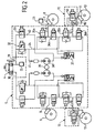
- FIG 2 there is shown in detail the hydraulic circuit of the brake system 1.
- the figure 2 represents in particular the interior of the pressure distributor 5 which, being of a conventional design for the ABS and ESP systems, will be described briefly.
- the front stage of the master cylinder 4 is connected by a hydraulic line 30 to a first portion of the pressure distributor 5 which controls two hydraulic brakes diagonally opposite.
- the rear stage of the master cylinder 4 is connected by a hydraulic line 31 to a second portion of the pressure distributor which also controls two hydraulic brakes diagonally opposite.
- the two halves of the dispenser 5 being perfectly symmetrical, only the right half will be described below.
- the hydraulic line 31 supplies in parallel an isolation solenoid valve 32 which is normally conducting and a supply solenoid valve 33 which is normally non-conducting.
- a hydraulic line 34 supplies in parallel the hydraulic line 8 for the front brake 7, via an application solenoid valve 35a, and the hydraulic line 10 for the brake back, via an application solenoid valve 35b.
- the hydraulic line 8 is connected to a pressure accumulator 37 via a release solenoid valve 36a and the hydraulic line 10 via a release solenoid valve 36b.
- the output of the pressure accumulator 37 equipped with a non-return valve, is connected to a pump 38 driven by a motor 39.
- the output of the pump 38 is connected by a hydraulic line 41 to the hydraulic line 34.
- a hydraulic line 40 connects the output of the supply solenoid valve 33 to the inlet of the pump 38. As shown in FIG.
- the position of the different solenoid valves corresponds to a functioning of the brakes as service brakes under the control of the master cylinder 4.
- the application solenoid valves 35a and 35b and the release solenoid valves 36a and 36b have a well-known operation in the framework of ABS systems.
- the pressure distributor 5 also makes it possible to send a control pressure into the front and rear hydraulic brakes without any action on the brake pedal 2 being necessary.
- the supply solenoid valve 33 is switched to the pass position and the isolation solenoid valve 32 is switched to its proportional position.
- the pump 38 is turned on to create the necessary control pressure which is conveyed to the brake caliper before 7 and the rear brake caliper 11, via the hydraulic lines 34, 8 and 10.
- branch box 12 has been shown in the form of its equivalent hydraulic diagram.
- the junction box 12 comprises an input connector 45 which is connected to the hydraulic line 10 and a hydraulic circuit of which a first branch 46 connects the input connector 45 to an output connector 47 and a second branch 48 in branch with the first connects the input connector 45 to an output connector 49 through a solenoid valve 50 normally closed.
- a hydraulic line 55 connects the output connector 47 to the input connector 58 of a cylinder body 60.
- a hydraulic line 56 connects the output connector 49 to a hydraulic cylinder 57 which is attached to a wing 68 of the body of the cylinder. hydraulic brake caliper 11 by a screw 59.
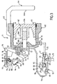
- the hydraulic brake caliper 11 comprises a rigid body which is intended to be connected, in a conventional manner, to the chassis of the vehicle with a freedom of lateral displacement with respect to a not shown brake disc. From left to right on the figure 3 this rigid body comprises the support wing 68 which is integral with the cylinder body 60, in which is defined a chamber 61, and an upper element 63 which connects the cylinder body 60 to a counter-abutment element 64.
- a piston 62 is slidably housed in the chamber 61.
- a sealing ring 65 seals between the piston 62 and the cylinder body 60.
- the abutment element 64 and the piston 62 have two surfaces 62a and 64a which face each other and which are intended to carry friction lining not shown to brake a not shown brake disc.
- the hydraulic brake caliper 11 also includes a piston locking device 62 for acting as an integrated parking brake.
- a pusher 66 is slidably housed in the chamber 61 and has a free end 73 which projects out of the cylinder body 60.
- a sealing ring 67 seals between the pusher 66 and the cylinder body 60.
- the pusher 66 is advantageously constituted by a threaded rod 66a and a complementary threaded bushing 66b which can bear on the inner face piston 62.
- the locking device is passive, that is to say that the parking brake is released.
- the movements of the pusher 66 are controlled by a pivoting lever 70 which is rotatably mounted about an axis 71 fixed to the support flange 68.
- the lever 70 is integral in rotation with an eccentric cam 72 which cooperates with the end 73 of the pusher 66.
- the lever 70 is connected to a rack 77 by means of a pivot pin 78.
- the rack 77 is guided in longitudinal sliding by tabs 79 connected to the wing 68 of the caliper body.
- the hydraulic cylinder 57 actuates the lever 70.
- the cylinder 57 comprises a cylinder body 74 which is connected to the wing 68 and a piston 75 which slides in the cylinder body 74 and whose free end can push a tab 76 rigidly connected to the lever 70.
- the solenoid valve 50 which selectively controls the supply of the hydraulic cylinder 57 comprises an electromagnet 89 fed by a control line 85 which is connected to the brake computer 6, as visible on the figure 1 . It also comprises a piston 91 which carries a lip seal 92 and which is held in the closed position shown on FIG. figure 3 by a return spring 90.
- the hydraulic cylinder 57 can rotate the lever 70 to set the parking brake, as will be explained below.
- a latch 80 is provided on the flange 68 to be able to lock the lever 70 in position via the rack 77.
- the latch 80 includes a stop lever 82 which pivots about an axis 88 and which is held in its release position shown on the figure 3 by a return spring 81.
- An electromagnet 83 controlled by a control line 84 connected to the braking computer 6, makes it possible to pivot the lever 82 in its locking position shown on FIG. figure 4 .
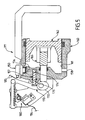
- the figure 4 represents the rear hydraulic brake after applying the parking brake.
- the brake computer 6 controls the pressure distributor 5 to apply, in each of the two rear brakes, a high control pressure in the chamber 61, which pushes the piston 62 into a position of appropriate tightening.
- the control pressure can be predetermined or calculated by the braking computer 6 according to different parameters, such as the mass of the vehicle and the slope on which the vehicle is.
- the isolation valve 32 and the supply valve 33 are switched as mentioned above.
- Each front application valve 35a is made non-conducting to isolate the front brake of the hydraulic line 34.
- the computer 6 controls the opening of the solenoid valve 50 , which is shown in the open position on the figure 4 .
- the piston 91 is retracted into the electromagnet 89, so that the lip seal 92 no longer blocks the communication between the input connector 45 and the output connector 49 of the housing 12.
- the jack 57 receives therefore the control pressure from the hydraulic line 10 and through the line 56, which pushes the piston 75 in the direction indicated by the arrow 95, so as to rotate the lever 70 in the direction indicated by the arrow 96.
- Cam 72 thus pushes the pusher 66 to apply it firmly against the inner surface of the piston 62.
- the cylinder 57 When pivoting the lever 70, the cylinder 57 only has to overcome the force of the return spring of the lever 70 and the friction forces acting. on the lever 70 and the pusher 66. In particular, it is not the cylinder 57 which clamps the piston 62 against the brake disc. As a result, the cylinder 57 is significantly smaller than the cylinder body 60.
- the computer 86 controls the supply of the electromagnet 83 via the line 84, so as to pivot the stop lever 82 in its locked position shown in FIG. figure 4 .
- a tooth of the stop lever 82 engages with a tooth of the rack 77, so as to lock the latter in position.
- the pressure of control in line 10 is removed by switching isolating valves 32 and supply 33 into their initial positions shown in FIG. figure 2 and the solenoid valve 50 is closed.
- the pusher 66 remains constrained between the piston 62 and the cam 72.
- the pusher 66 constrains the lever 70 in the direction opposite to the arrow 96, so that the latching between the stop lever 82 and the rack 77 remains firmly maintained without the need to continue feeding the electromagnet 83.
- the brake can thus remain tight for a long time without supplying hydraulic pressure and without power supply or the solenoid valve 50 and the electromagnet 83 .
- the lip seal 92 in the closed position does not prevent a return of the hydraulic fluid from the cylinder 57 to the control line 10 after the control pressure has been interrupted therein.
- the solenoid valve 50, in the closed position therefore acts as a unidirectional valve, as represented symbolically by the valve 99 on the figure 2 .
- a high control pressure is again sent in the hydraulic line 10 and the solenoid valve 50 is opened, so that the cylinder 57 produces a slight pivoting of the lever 70 in the direction of the arrow 96, from the position of the figure 4 .
- This movement releases the snap between the stop lever 82 and the rack 77, so that the lever 82 returns to the release position under the action of the return spring 81, without the electromagnet 83 intervenes.
- the control pressure is then interrupted and the solenoid valve 50 is closed again.
- the pressure drop in the chamber 61 causes the piston 62 to return to its loosened position.
- the thrust of the pusher 66 against the cam 72 and the action of the lever return spring 70 act together to return the lever 70 to its inoperative position. figure 3 .
- the brake caliper 11 can then again function as a hydraulic service brake.
- An emergency lever 100 is provided for releasing the parking brake in the event that a failure of the solenoid valve 50 or cylinder 57 would prevent actuation of the cylinder after the parking brake has been applied.
- the emergency lever 100 which is shown on the figure 1 , is arranged to allow to exert on the rack 77 or on the lever 70 a traction in the direction of the arrow 101 represented on the figure 4 .
- the emergency lever 100 can be placed in the trunk of the vehicle or at any other location where it is both accessible when needed, but does not interfere with the driver in normal
- the rear hydraulic brake according to the embodiment described above has the advantage of being able to be manufactured by adding the necessary components to a pre-existing integrated parking brake hydraulic brake caliper, without the need to modify in depth the design of the stirrup.
- the rear hydraulic brake does not have a branch box.
- similar elements in the first embodiment are designated by the same reference numeral increased by 100. Only the essential differences from the first embodiment are described below.
- the brake caliper 111 has a hydraulic inlet 158 for the connection of the hydraulic line 10.
- the cylinder 157 for applying the parking brake comprises a piston 175 housed in a cylindrical bore 174 which is formed directly in the wall of the cylinder body 160.
- the fluid supply of the cylinder 157 is through a channel 156 which is also formed in the wall of the cylinder body 160 and which connects the chamber 161 to the cylindrical bore 174 through the solenoid valve 150.
- L The solenoid valve 150 is attached to the cylinder body 160 to control the flow in the channel 156. Furthermore, the operation of this brake is identical to the first embodiment.
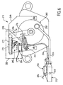
- the rear hydraulic brake comprises the junction box 212 and the brake caliper 211.
- elements similar to the first embodiment are designated by the same reference numeral increased by 200. Except for geometrical details the housing 212 is identical to the housing 12. The only essential difference with respect to the brake of the first embodiment lies in the device blocking of the piston.
- the pivot axis 271 of the lever 270 is connected to the cylinder body 260 and parallel to the axis thereof. The lever 270, the rack 277 and the jack 257 therefore move in a plane perpendicular to the similar elements of the first embodiment.
- the transmission mechanism (not shown) between the lever 270 and the brake piston comprises a threaded rod engaged in the cylinder body 260 and rotatably connected to the lever 270 and a nut. engaged on it.
- This nut is immobilized in rotation to translate along the threaded rod in the cylinder body 260 as a function of the rotation thereof and is firmly applied against the rear surface of the brake piston, in the manner of the pusher 66 when the lever 270 is rotated in the direction of the arrow 296.
- the operation of this brake is identical to the first embodiment.
- the lock 280 is identical to the latch 80 of the figure 3 , except the reverse orientation of the ratchet teeth.
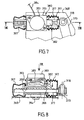
- a lock 380 can be used which is shown on the Figures 7 and 8 .
- the figure 7 represents zone VII of the figure 6 correspondingly modified.
- the elements similar to the first embodiment are designated by the same reference numeral increased by 300.
- the latch 380 is shown in the release position on the Figures 7 and 8 . It comprises a housing 393 which contains the electromagnet 383, the stop lever 382 pivoting about the axis 388 and its return spring 381.
- the housing 393 has a through passage 398 in which the rack 377 is engaged and comprises a fixing element 394 for fastening the lock to the wing 368 of the caliper body. Rubber gussets 397 are attached to the housing 393 and protect the rack 377 against dust. Furthermore, the operation of the latch 380 is identical to that of the latch 280. The latch 380 can also be adapted instead of the latches 80 and 180.
- the rear brakes described above therefore function as hydraulic service brakes and self-tightening and unclamping parking brakes.
- the locking and unlocking of the two rear brakes can be controlled by means of a parking brake control button 25 connected to the bus 15, visible on the figure 1 .
- a parking brake control button 25 connected to the bus 15, visible on the figure 1 .
- the slope maintenance function is provided by the braking computer 6 programmed accordingly.
- the four hydraulic brakes are automatically tightened with sufficient hydraulic pressure to immobilize the vehicle, which pressure depends in particular on the slope value.
- each isolation valve 32 and each supply valve 33 of the pressure distributor 5 is switched and the necessary control pressure is generated by each pump 38.
- the pressure level reached is controlled by means of the sensor 23.
- the four hydraulic brakes are automatically released as soon as an exit condition is validated, typically when an action of the driver is detected, reflecting the desire to restart. However, if the automatic activation status of the hydraulic brakes is prolonged for a long time without the exit condition being validated, there is the risk of a loss of pressure in the hydraulic circuit or an excessive consumption of fuel. energy through the pressure distributor 5.
- the slope maintenance function is programmed so as to automatically activate the clamping of the parking brakes on the rear axle when the hydraulic clamping of the brakes is maintained for a duration greater than a predetermined threshold, for example 40 seconds.
- a predetermined threshold for example 40 seconds.
- a stopwatch is initialized to measure the time during which the hydraulic clamping is maintained.
- a Rear parking brake release control is generated.
- Activation of the locking device of the brake piston is then performed automatically by the hydraulic cylinder as described above.
- the pressure in the hydraulic lines 8 and 10 can then be suppressed by switching each isolation valve 32 and each supply valve 33 into its initial position represented on the figure 2 .
Landscapes
- Engineering & Computer Science (AREA)
- Transportation (AREA)
- Mechanical Engineering (AREA)
- Physics & Mathematics (AREA)
- Fluid Mechanics (AREA)
- Regulating Braking Force (AREA)
- Braking Arrangements (AREA)
Claims (15)
- Hydraulische Bremse, die einen Körper (60), in dem zumindest eine Kammer (61) gebildet ist, die an einer hydraulischen Leitung (10) angeschlossen ist, um einen Steuerdruck zu empfangen, und einen Kolben (62) aufweist, der geeignet ist, sich in der Kammer zwischen einer Ruheposition und einer Bremsposition in Antwort auf den Steuerdruck zu bewegen, wobei die hydraulische Bremse eine Kolbenblockierungsvorrichtung (66, 70) aufweist, die zwischen einer passiven Position, in der die Kolbenblockierungsvorrichtung (66, 70) den Kolben (62) sich in Antwort auf den Steuerdruck bewegen lässt, und einer aktiven Position, in der die Kolbenblockierungsvorrichtung (66, 70) den Kolben (62) in der Bremsposition nach Einstellung des Steuerdrucks blockiert, betätigbar ist, wobei die hydraulische Bremse ein hydraulisches Stellglied (57) aufweist, das an der hydraulischen Leitung (10) angeschlossen ist, um denselben Steuerdruck zu empfangen wie die Kammer (61) und das geeignet ist, die Kolbenblockierungsvorrichtung (70, 66) in Richtung der aktiven Position in Antwort auf den Steuerdruck zu betätigen, gekennzeichnet durch die Tatsache, dass sie ein Ventil (50) aufweist, das selektiv geöffnet oder geschlossen werden kann, um den Steuerdruck, der in der Kammer (61) angewandt wird, an das hydraulische Stellglied (57) zu übertragen oder nicht zu übertragen.
- Hydraulische Bremse gemäß Anspruch 1, in der die Kolbenblockierungsvorrichtung einen Hebel (70, 170, 270), der durch das hydraulische Stellglied (57, 157, 257) betätigbar ist und außerhalb der Kammer angeordnet ist, und einen Übertragungsmechanismus aufweist, der zwischen dem Hebel (70, 170, 270) und dem Kolben (62) angeordnet ist, um eine Bewegung des Hebels an einen Schieber (66, 166) zu übertragen, der in dem Körper (60, 160) untergebracht ist und geeignet ist, sich fest gegen einer innere Oberfläche des Kolbens (62, 162) in der aktiven Position der Blockierungsvorrichtung zu legen.
- Hydraulische Bremse gemäß Anspruch 1, in der der Übertragungsmechanismus einen exzentrischen Nocken (72, 172) drehfest zu dem Hebel (70, 170) und zusammenwirkend mit einem Endstück des Schiebers (66, 166) aufweist.
- Hydraulische Bremse gemäß Anspruch 2, in der der Übertragungsmechanismus eine Gewindestange aufweist, die in den Körper (260) eingeführt und drehfest zu dem Hebel (270) ist, wobei der Schieber (66, 166) eine Mutter aufweist, die auf die Gewindestange eingeführt und rotationsfeststehend ist, um sich entlang der Gewindestange in den Körper entsprechend der Rotation von dieser zu verschieben.
- Hydraulische Bremse gemäß Anspruch 2, 3, oder 4, gekennzeichnet durch die Tatsache, dass sie eine Verriegelung (80, 77) aufweist, die geeignet ist, den Hebel (70, 170, 270) in Position zu verriegeln, um die Kolbenblockierungsvorrichtung (66, 70) in der aktiven Position zu verriegeln.
- Hydraulische Bremse gemäß Anspruch 5, gekennzeichnet durch die Tatsache, dass die Verriegelung (80, 77), standardmäßig, einen Freigabezustand einnimmt, der die Betätigung der Kolbenblockierungsvorrichtung (66, 70) zwischen der passiven und der aktiven Position erlaubt, wobei die Verriegelung (80, 77) selektiv von der Freigabeposition bis zu einem Verriegelungszustand betätigbar ist, um die Kolbenblockierungsvorrichtung (66, 70) in Position zu verriegeln.
- Hydraulische Bremse gemäß Anspruch 5, gekennzeichnet durch die Tatsache, dass die Verriegelung eine Zahnstange (77, 277), die verschiebbar longitudinal auf einem Trägerelement (68) fest zu dem Körper (60) der hydraulischen Bremse geführt ist, und einen Sperrhebel (82) aufweist, der schwenkbar gegenüber dem Trägerelement (68) montiert ist, wobei der Sperrhebel (70, 270) geeignet ist, die Zahnstange (77, 277) in einem Verriegelungszustand der Verriegelung zu arretieren und die Zahnstange (77, 277) in einem Freigabezustand der Verriegelung sich verschieben lassen, wobei die Zahnstange (77, 277) mit dem Hebel (70, 270) verbunden ist.
- Hydraulische Bremse gemäß Anspruch 7, gekennzeichnet durch die Tatsache, dass die Verriegelung einen Elektromagneten (83) aufweist, der geeignet ist, den Sperrhebel (82) gegenüber einer Rückstellfeder (81) zum Schwenken zu bringen.
- Hydraulische Bremse gemäß einem der Ansprüche 1 bis 8, gekennzeichnet durch die Tatsache, dass das Ventil ein Magnetventil (50) ist, das standardmäßig eine geschlossene Position aufweist.
- Hydraulische Bremse gemäß einem der Ansprüche 1 bis 8, gekennzeichnet durch die Tatsache, dass das Ventil (50) eine geschlossene Position aufweist, in der es einen unidirektionalen Durchfluss von Fluid von dem hydraulischen Stellglied (57) in Richtung des der hydraulischen Leitung (10).
- Hydraulische Bremse gemäß einem der Ansprüche 1 bis 10, gekennzeichnet durch die Tatsache, dass sie ein Nebenschlussgehäuse (12) aufweist, das zwischen der hydraulischen Leitung (10) und dem Körper der hydraulischen Bremse (60) geschaltet ist, wobei das Nebenschlussgehäuse einen hydraulischen Eingang (45), der mit der hydraulischen Leitung (10) verbunden ist, zwei Schaltungspfade (46, 48), der eine im Nebenschluss gegenüber dem anderen, um den hydraulischen Eingang (45) mit jeweils zwei hydraulischen Ausgängen (47, 49) des Gehäuses zu verbinden und das Ventil (50), um den Abfluss in einen ersten (48) der Schaltungspfade zu steuern, wobei die hydraulische Bremse des Weiteren zwei hydraulische Verbindungen (56, 55) aufweist, die jeweils den Ausgang des ersten Zweiges mit dem hydraulischen Stellglied (57) und den Ausgang des anderen Zweiges mit der Kammer (61) verbinden.
- Hydraulische Bremse gemäß einem der Ansprüche 1 bis 10, gekennzeichnet durch die Tatsache, dass der Körper der hydraulischen Bremse (160) eine hydraulische Verbindung (156), die die Kammer (161) mit dem hydraulischen Stellglied (157) verbindet, und das Ventil (150) aufweist, das eingerichtet ist, um den Abfluss in die hydraulische Verbindung (156) zu steuern.
- Hydraulische Bremse gemäß einem der Ansprüche 1 bis 12, gekennzeichnet durch die Tatsache, dass die hydraulische Leitung (10) mit einem Druckverteiler (5) verbunden ist, der mit einer Pumpe (38) ausgestattet ist, die geeignet ist, den Steuerdruck zu erzeugen.
- Verwendung einer hydraulischen Bremse (11, 12; 111; 211, 212) gemäß einem der Ansprüche 1 bis 13 als eine Feststellbremse eines Kraftfahrzeugs, gekennzeichnet durch die Schritte, die bestehen aus:Erzeugen eines Feststellbremsensteuersignals,Senden eines Steuerdrucks in die hydraulische Leitung (10) in Antwort auf das Feststellbremsensteuersignals, um den Kolben (62, 162) bis zu der Bremsposition zu verschieben,Öffnen des Ventils (50, 150, 250), um die Kolbenblockierungsvorrichtung (70, 66; 170, 166; 270) bis zu der aktiven Position mit Hilfe des hydraulischen Stellglieds (57, 157, 257) zu betätigen,Beenden des Steuerdrucks in der hydraulischen Leitung (10), während der Kolben (62, 162) in der Bremsposition durch die Kolbenblockierungsvorrichtung (70, 66; 170, 166, 270) in der aktiven Position blockiert bleibt.
- Verwendung einer hydraulischen Bremse gemäß einem der Ansprüche 1 bis 13, um ein Kraftfahrzeug automatisch auf einem Gefälle zu halten, gekennzeichnet durch die Schritte, die bestehen aus:Erkennen eines Haltezustands des Kraftfahrzeugs auf einem Gefälle,Senden eines Steuerdrucks in die hydraulische Leitung (10) in Antwort auf die Erkennung, um den Kolben (62, 162) bis zu der Bremsposition zu verschieben, um das Fahrzeug auf dem Gefälle zum Stehen zu bringen,Messen einer Dauer, während der der Kolben (62, 162) in der Bremsposition bleibt,wenn die Dauer einen vorbestimmten Wert übersteigt, Öffnen des Ventils (50, 150, 250), um die Kolbenblockierungsvorrichtung (70, 66; 170, 166; 270) bis zu der aktiven Position mit Hilfe des hydraulischen Stellglieds (57, 157, 257) zu betätigen,Beenden des Steuerdrucks in der hydraulischen Leitung (10), während der Kolben (62, 162) in der Bremsposition durch die Kolbenblockierungsvorrichtung (70, 66; 170, 166, 270) in der aktiven Position blockiert bleibt.
Priority Applications (1)
| Application Number | Priority Date | Filing Date | Title |
|---|---|---|---|
| EP20030292990 EP1538363B1 (de) | 2003-12-01 | 2003-12-01 | Hydraulische Feststellbremse und Verfahren zu deren Verwendung in einer Neigung |
Applications Claiming Priority (1)
| Application Number | Priority Date | Filing Date | Title |
|---|---|---|---|
| EP20030292990 EP1538363B1 (de) | 2003-12-01 | 2003-12-01 | Hydraulische Feststellbremse und Verfahren zu deren Verwendung in einer Neigung |
Publications (2)
| Publication Number | Publication Date |
|---|---|
| EP1538363A1 EP1538363A1 (de) | 2005-06-08 |
| EP1538363B1 true EP1538363B1 (de) | 2012-05-30 |
Family
ID=34443107
Family Applications (1)
| Application Number | Title | Priority Date | Filing Date |
|---|---|---|---|
| EP20030292990 Expired - Lifetime EP1538363B1 (de) | 2003-12-01 | 2003-12-01 | Hydraulische Feststellbremse und Verfahren zu deren Verwendung in einer Neigung |
Country Status (1)
| Country | Link |
|---|---|
| EP (1) | EP1538363B1 (de) |
Families Citing this family (6)
| Publication number | Priority date | Publication date | Assignee | Title |
|---|---|---|---|---|
| US20090071768A1 (en) * | 2004-11-17 | 2009-03-19 | Brian Anthony Paulsen | Mechanical Disc Braking Assembly |
| DE102006035913A1 (de) * | 2005-08-02 | 2007-03-08 | Continental Teves Ag & Co. Ohg | Kombinierte Fahrzeugbremsanlage mit hydraulisch und elektromechanisch betätigbaren Radbremsen |
| FR2910867B1 (fr) * | 2006-12-28 | 2009-04-10 | Peugeot Citroen Automobiles Sa | Procede de commande de la suppression de l'enfoncement de la pedale de frein lors de l'engagement du frein de stationnem ent d'un vehicule automobile, systeme de commande et vehicu le associes |
| FR2931771B1 (fr) * | 2008-05-29 | 2010-10-15 | Peugeot Citroen Automobiles Sa | Systeme de controle de stabilite et de trajectoire d'un vehicule automobile utilisant un servofrein actif. |
| FR2931773B1 (fr) * | 2008-05-29 | 2010-10-15 | Peugeot Citroen Automobiles Sa | Systeme de controle de stabilite et de trajectoire d'un vehicule automobile utilisant un servofrein actif. |
| FR2931772B1 (fr) * | 2008-05-29 | 2010-10-15 | Peugeot Citroen Automobiles Sa | Systeme de controle de stabilite et de trajectoire d'un vehicule automobile utilisant un servofrein actif. |
Family Cites Families (4)
| Publication number | Priority date | Publication date | Assignee | Title |
|---|---|---|---|---|
| US5127495A (en) * | 1990-09-28 | 1992-07-07 | Allied-Signal Inc. | Parking brake and method therefor |
| US5161650A (en) * | 1991-05-22 | 1992-11-10 | Allied-Signal Inc. | Disc brake with powered integral parking mechanism |
| DE19502927A1 (de) * | 1995-01-31 | 1996-08-01 | Teves Gmbh Alfred | Kombinierte Betriebs- und Feststellbremse |
| DE19848448C2 (de) * | 1998-10-21 | 2001-12-13 | Daimler Chrysler Ag | Bremsdruck-Steuerungseinrichtung einer Bremsanlage eines Straßenfahrzeuges |
-
2003
- 2003-12-01 EP EP20030292990 patent/EP1538363B1/de not_active Expired - Lifetime
Also Published As
| Publication number | Publication date |
|---|---|
| EP1538363A1 (de) | 2005-06-08 |
Similar Documents
| Publication | Publication Date | Title |
|---|---|---|
| EP2826684B1 (de) | Schienenbremssystem und Bremsverfahren eines Schienenfahrzeugs, das ein solches System umfasst | |
| EP0065451B1 (de) | Bremsdruckmodulator für Blockierschutzsysteme | |
| FR2553726A1 (fr) | Systeme de freinage assiste de vehicule automobile | |
| EP1538363B1 (de) | Hydraulische Feststellbremse und Verfahren zu deren Verwendung in einer Neigung | |
| EP0342091B1 (de) | Gesteuertes Ventil für ein Antiblockiersystem | |
| FR2984265A1 (fr) | Frein a disque a fonction combinee de frein de service et de frein de stationnement a alimentation hydraulique | |
| EP1542891A1 (de) | Pneumatischer bremskraftverstärker | |
| EP2103493A1 (de) | Kraftfahrzeugstabilitäts- und Kraftfahrzeugbahnsteuersystem mit aktivem Bremskraftverstärker | |
| FR2550149A1 (fr) | Generateur de pression de freinage pour systeme de freinage de vehicule | |
| FR2931769A1 (fr) | Systeme de feinage permettant la mise en oeuvre d'un procede de controle de stabilite et de trajectoire dans un vehicule muni d'elements de frein motorises. | |
| FR2471898A2 (fr) | Systeme de freinage hydraulique | |
| EP2098425A1 (de) | Bremssysteme, die die Ausführung eines Stabilitäts- und Bewegungsbahnsteuerverfahrens erlauben | |
| CA2875269C (fr) | Systeme de freinage ferroviaire et procede de freinage d'un vehicule ferroviaire comportant un tel systeme | |
| FR2878804A1 (fr) | Assemblage de vanne pour des freins anti-patinage d'un avion | |
| EP2253521B1 (de) | Servobremse mit Magnetventil | |
| EP2128478A1 (de) | Bremssystem zur Kontrolle der Stabilität und der Bewegungsbahn eines Kraftfahrzeugs, und Anwendungsverfahren dieses Systems | |
| EP0725226B1 (de) | Scheibenbremse mit verringerter Absorption | |
| FR2931766A1 (fr) | Systeme de freinage avec controle de stabilite et de trajectoire et elements de frein motorises. | |
| FR2751601A1 (fr) | Actionneur hydromecanique | |
| FR2931767A1 (fr) | Systeme de freinage pour le controle de stabilite et de traj ectoire d'un vehicule automobile et procedes d'utilisation d 'un tel systeme | |
| FR2468491A1 (fr) | Correcteur de freinage asservi a la deceleration | |
| WO2004051111A1 (fr) | Circuit de freinage comportant un frein de parking hydraulique. | |
| FR2774642A1 (fr) | Dispositif de limitation de l'effort sur la pedale de freinage d'un vehicule | |
| FR2928327A1 (fr) | Systeme de freinage mettant en oeuvre des elements de frein motorises pour le controle de stabilite et de trajectoire d'un vehicule automobile et procedes d'utilisation de ce systeme associes. | |
| EP1870304A1 (de) | Kraftfahrzeugbremssystem mit einer zusätzlichen Bremskraftverstärkungsvorrichtung. |
Legal Events
| Date | Code | Title | Description |
|---|---|---|---|
| PUAI | Public reference made under article 153(3) epc to a published international application that has entered the european phase |
Free format text: ORIGINAL CODE: 0009012 |
|
| 17P | Request for examination filed |
Effective date: 20040823 |
|
| AK | Designated contracting states |
Kind code of ref document: A1 Designated state(s): AT BE BG CH CY CZ DE DK EE ES FI FR GB GR HU IE IT LI LU MC NL PT RO SE SI SK TR |
|
| AX | Request for extension of the european patent |
Extension state: AL LT LV MK |
|
| AKX | Designation fees paid |
Designated state(s): AT BE BG CH CY CZ DE DK EE ES FI FR GB GR HU IE IT LI LU MC NL PT RO SE SI SK TR |
|
| 17Q | First examination report despatched |
Effective date: 20090630 |
|
| RIC1 | Information provided on ipc code assigned before grant |
Ipc: B60T 8/34 20060101ALI20111014BHEP Ipc: B60T 8/32 20060101ALI20111014BHEP Ipc: B60T 7/12 20060101ALI20111014BHEP Ipc: B60T 8/48 20060101ALI20111014BHEP Ipc: F16D 65/20 20060101AFI20111014BHEP Ipc: F16D 65/14 20060101ALI20111014BHEP |
|
| GRAP | Despatch of communication of intention to grant a patent |
Free format text: ORIGINAL CODE: EPIDOSNIGR1 |
|
| RAP1 | Party data changed (applicant data changed or rights of an application transferred) |
Owner name: BWI COMPANY LIMITED S.A. |
|
| GRAS | Grant fee paid |
Free format text: ORIGINAL CODE: EPIDOSNIGR3 |
|
| REG | Reference to a national code |
Ref country code: DE Ref legal event code: R079 Ref document number: 60341080 Country of ref document: DE Free format text: PREVIOUS MAIN CLASS: F16D0065200000 Ipc: F16D0065180000 |
|
| GRAA | (expected) grant |
Free format text: ORIGINAL CODE: 0009210 |
|
| RIC1 | Information provided on ipc code assigned before grant |
Ipc: B60T 8/48 20060101ALI20120418BHEP Ipc: B60T 7/12 20060101ALI20120418BHEP Ipc: B60T 8/34 20060101ALI20120418BHEP Ipc: B60T 8/32 20060101ALI20120418BHEP Ipc: F16D 65/18 20060101AFI20120418BHEP Ipc: F16D 65/14 20060101ALI20120418BHEP |
|
| AK | Designated contracting states |
Kind code of ref document: B1 Designated state(s): AT BE BG CH CY CZ DE DK EE ES FI FR GB GR HU IE IT LI LU MC NL PT RO SE SI SK TR |
|
| REG | Reference to a national code |
Ref country code: GB Ref legal event code: FG4D Free format text: NOT ENGLISH |
|
| REG | Reference to a national code |
Ref country code: CH Ref legal event code: EP |
|
| REG | Reference to a national code |
Ref country code: DE Ref legal event code: R082 Ref document number: 60341080 Country of ref document: DE Representative=s name: DILG HAEUSLER SCHINDELMANN PATENTANWALTSGESELL, DE |
|
| REG | Reference to a national code |
Ref country code: AT Ref legal event code: REF Ref document number: 560213 Country of ref document: AT Kind code of ref document: T Effective date: 20120615 |
|
| REG | Reference to a national code |
Ref country code: IE Ref legal event code: FG4D Free format text: LANGUAGE OF EP DOCUMENT: FRENCH |
|
| REG | Reference to a national code |
Ref country code: DE Ref legal event code: R096 Ref document number: 60341080 Country of ref document: DE Effective date: 20120726 |
|
| REG | Reference to a national code |
Ref country code: NL Ref legal event code: VDEP Effective date: 20120530 |
|
| PG25 | Lapsed in a contracting state [announced via postgrant information from national office to epo] |
Ref country code: SE Free format text: LAPSE BECAUSE OF FAILURE TO SUBMIT A TRANSLATION OF THE DESCRIPTION OR TO PAY THE FEE WITHIN THE PRESCRIBED TIME-LIMIT Effective date: 20120530 Ref country code: FI Free format text: LAPSE BECAUSE OF FAILURE TO SUBMIT A TRANSLATION OF THE DESCRIPTION OR TO PAY THE FEE WITHIN THE PRESCRIBED TIME-LIMIT Effective date: 20120530 Ref country code: CY Free format text: LAPSE BECAUSE OF FAILURE TO SUBMIT A TRANSLATION OF THE DESCRIPTION OR TO PAY THE FEE WITHIN THE PRESCRIBED TIME-LIMIT Effective date: 20120530 |
|
| REG | Reference to a national code |
Ref country code: AT Ref legal event code: MK05 Ref document number: 560213 Country of ref document: AT Kind code of ref document: T Effective date: 20120530 |
|
| PG25 | Lapsed in a contracting state [announced via postgrant information from national office to epo] |
Ref country code: GR Free format text: LAPSE BECAUSE OF FAILURE TO SUBMIT A TRANSLATION OF THE DESCRIPTION OR TO PAY THE FEE WITHIN THE PRESCRIBED TIME-LIMIT Effective date: 20120831 Ref country code: SI Free format text: LAPSE BECAUSE OF FAILURE TO SUBMIT A TRANSLATION OF THE DESCRIPTION OR TO PAY THE FEE WITHIN THE PRESCRIBED TIME-LIMIT Effective date: 20120530 |
|
| PG25 | Lapsed in a contracting state [announced via postgrant information from national office to epo] |
Ref country code: EE Free format text: LAPSE BECAUSE OF FAILURE TO SUBMIT A TRANSLATION OF THE DESCRIPTION OR TO PAY THE FEE WITHIN THE PRESCRIBED TIME-LIMIT Effective date: 20120530 Ref country code: RO Free format text: LAPSE BECAUSE OF FAILURE TO SUBMIT A TRANSLATION OF THE DESCRIPTION OR TO PAY THE FEE WITHIN THE PRESCRIBED TIME-LIMIT Effective date: 20120530 Ref country code: AT Free format text: LAPSE BECAUSE OF FAILURE TO SUBMIT A TRANSLATION OF THE DESCRIPTION OR TO PAY THE FEE WITHIN THE PRESCRIBED TIME-LIMIT Effective date: 20120530 Ref country code: NL Free format text: LAPSE BECAUSE OF FAILURE TO SUBMIT A TRANSLATION OF THE DESCRIPTION OR TO PAY THE FEE WITHIN THE PRESCRIBED TIME-LIMIT Effective date: 20120530 Ref country code: DK Free format text: LAPSE BECAUSE OF FAILURE TO SUBMIT A TRANSLATION OF THE DESCRIPTION OR TO PAY THE FEE WITHIN THE PRESCRIBED TIME-LIMIT Effective date: 20120530 Ref country code: SK Free format text: LAPSE BECAUSE OF FAILURE TO SUBMIT A TRANSLATION OF THE DESCRIPTION OR TO PAY THE FEE WITHIN THE PRESCRIBED TIME-LIMIT Effective date: 20120530 Ref country code: CZ Free format text: LAPSE BECAUSE OF FAILURE TO SUBMIT A TRANSLATION OF THE DESCRIPTION OR TO PAY THE FEE WITHIN THE PRESCRIBED TIME-LIMIT Effective date: 20120530 |
|
| PG25 | Lapsed in a contracting state [announced via postgrant information from national office to epo] |
Ref country code: IT Free format text: LAPSE BECAUSE OF FAILURE TO SUBMIT A TRANSLATION OF THE DESCRIPTION OR TO PAY THE FEE WITHIN THE PRESCRIBED TIME-LIMIT Effective date: 20120530 Ref country code: PT Free format text: LAPSE BECAUSE OF FAILURE TO SUBMIT A TRANSLATION OF THE DESCRIPTION OR TO PAY THE FEE WITHIN THE PRESCRIBED TIME-LIMIT Effective date: 20121001 |
|
| PGFP | Annual fee paid to national office [announced via postgrant information from national office to epo] |
Ref country code: FR Payment date: 20130107 Year of fee payment: 10 |
|
| PLBE | No opposition filed within time limit |
Free format text: ORIGINAL CODE: 0009261 |
|
| STAA | Information on the status of an ep patent application or granted ep patent |
Free format text: STATUS: NO OPPOSITION FILED WITHIN TIME LIMIT |
|
| PG25 | Lapsed in a contracting state [announced via postgrant information from national office to epo] |
Ref country code: ES Free format text: LAPSE BECAUSE OF FAILURE TO SUBMIT A TRANSLATION OF THE DESCRIPTION OR TO PAY THE FEE WITHIN THE PRESCRIBED TIME-LIMIT Effective date: 20120910 |
|
| 26N | No opposition filed |
Effective date: 20130301 |
|
| BERE | Be: lapsed |
Owner name: BWI COMPANY LIMITED S.A. Effective date: 20121231 |
|
| REG | Reference to a national code |
Ref country code: DE Ref legal event code: R097 Ref document number: 60341080 Country of ref document: DE Effective date: 20130301 |
|
| PG25 | Lapsed in a contracting state [announced via postgrant information from national office to epo] |
Ref country code: BG Free format text: LAPSE BECAUSE OF FAILURE TO SUBMIT A TRANSLATION OF THE DESCRIPTION OR TO PAY THE FEE WITHIN THE PRESCRIBED TIME-LIMIT Effective date: 20120830 Ref country code: MC Free format text: LAPSE BECAUSE OF NON-PAYMENT OF DUE FEES Effective date: 20121231 |
|
| REG | Reference to a national code |
Ref country code: CH Ref legal event code: PL |
|
| GBPC | Gb: european patent ceased through non-payment of renewal fee |
Effective date: 20121201 |
|
| REG | Reference to a national code |
Ref country code: IE Ref legal event code: MM4A |
|
| PG25 | Lapsed in a contracting state [announced via postgrant information from national office to epo] |
Ref country code: BE Free format text: LAPSE BECAUSE OF NON-PAYMENT OF DUE FEES Effective date: 20121231 |
|
| PG25 | Lapsed in a contracting state [announced via postgrant information from national office to epo] |
Ref country code: IE Free format text: LAPSE BECAUSE OF NON-PAYMENT OF DUE FEES Effective date: 20121201 Ref country code: LI Free format text: LAPSE BECAUSE OF NON-PAYMENT OF DUE FEES Effective date: 20121231 Ref country code: CH Free format text: LAPSE BECAUSE OF NON-PAYMENT OF DUE FEES Effective date: 20121231 |
|
| PG25 | Lapsed in a contracting state [announced via postgrant information from national office to epo] |
Ref country code: GB Free format text: LAPSE BECAUSE OF NON-PAYMENT OF DUE FEES Effective date: 20121201 |
|
| PG25 | Lapsed in a contracting state [announced via postgrant information from national office to epo] |
Ref country code: TR Free format text: LAPSE BECAUSE OF FAILURE TO SUBMIT A TRANSLATION OF THE DESCRIPTION OR TO PAY THE FEE WITHIN THE PRESCRIBED TIME-LIMIT Effective date: 20120530 |
|
| PG25 | Lapsed in a contracting state [announced via postgrant information from national office to epo] |
Ref country code: LU Free format text: LAPSE BECAUSE OF NON-PAYMENT OF DUE FEES Effective date: 20121201 |
|
| PG25 | Lapsed in a contracting state [announced via postgrant information from national office to epo] |
Ref country code: HU Free format text: LAPSE BECAUSE OF FAILURE TO SUBMIT A TRANSLATION OF THE DESCRIPTION OR TO PAY THE FEE WITHIN THE PRESCRIBED TIME-LIMIT Effective date: 20031201 |
|
| REG | Reference to a national code |
Ref country code: FR Ref legal event code: ST Effective date: 20140829 |
|
| PG25 | Lapsed in a contracting state [announced via postgrant information from national office to epo] |
Ref country code: FR Free format text: LAPSE BECAUSE OF NON-PAYMENT OF DUE FEES Effective date: 20131231 |
|
| PGFP | Annual fee paid to national office [announced via postgrant information from national office to epo] |
Ref country code: DE Payment date: 20181120 Year of fee payment: 16 |
|
| REG | Reference to a national code |
Ref country code: DE Ref legal event code: R119 Ref document number: 60341080 Country of ref document: DE |
|
| PG25 | Lapsed in a contracting state [announced via postgrant information from national office to epo] |
Ref country code: DE Free format text: LAPSE BECAUSE OF NON-PAYMENT OF DUE FEES Effective date: 20200701 |