EP1538388A1 - Ölkreislauf-Verfahren und -Vorrichtung - Google Patents
Ölkreislauf-Verfahren und -Vorrichtung Download PDFInfo
- Publication number
- EP1538388A1 EP1538388A1 EP04257396A EP04257396A EP1538388A1 EP 1538388 A1 EP1538388 A1 EP 1538388A1 EP 04257396 A EP04257396 A EP 04257396A EP 04257396 A EP04257396 A EP 04257396A EP 1538388 A1 EP1538388 A1 EP 1538388A1
- Authority
- EP
- European Patent Office
- Prior art keywords
- lubricant
- source
- bearing
- conduit
- reservoir
- Prior art date
- Legal status (The legal status is an assumption and is not a legal conclusion. Google has not performed a legal analysis and makes no representation as to the accuracy of the status listed.)
- Withdrawn
Links
- 239000000314 lubricant Substances 0.000 title claims abstract description 234
- 238000000034 method Methods 0.000 title claims abstract description 19
- 230000005484 gravity Effects 0.000 claims description 6
- 238000005461 lubrication Methods 0.000 claims description 6
- 230000000712 assembly Effects 0.000 description 8
- 238000000429 assembly Methods 0.000 description 8
- 238000001816 cooling Methods 0.000 description 7
- 238000006073 displacement reaction Methods 0.000 description 2
- 230000001050 lubricating effect Effects 0.000 description 2
- 238000012986 modification Methods 0.000 description 2
- 230000004048 modification Effects 0.000 description 2
- 238000004140 cleaning Methods 0.000 description 1
- 239000005068 cooling lubricant Substances 0.000 description 1
- 239000000498 cooling water Substances 0.000 description 1
- 230000003292 diminished effect Effects 0.000 description 1
- 230000000630 rising effect Effects 0.000 description 1
- XLYOFNOQVPJJNP-UHFFFAOYSA-N water Substances O XLYOFNOQVPJJNP-UHFFFAOYSA-N 0.000 description 1
Images


Classifications
-
- F—MECHANICAL ENGINEERING; LIGHTING; HEATING; WEAPONS; BLASTING
- F16—ENGINEERING ELEMENTS AND UNITS; GENERAL MEASURES FOR PRODUCING AND MAINTAINING EFFECTIVE FUNCTIONING OF MACHINES OR INSTALLATIONS; THERMAL INSULATION IN GENERAL
- F16N—LUBRICATING
- F16N7/00—Arrangements for supplying oil or unspecified lubricant from a stationary reservoir or the equivalent in or on the machine or member to be lubricated
- F16N7/14—Arrangements for supplying oil or unspecified lubricant from a stationary reservoir or the equivalent in or on the machine or member to be lubricated the lubricant being conveyed from the reservoir by mechanical means
- F16N7/16—Arrangements for supplying oil or unspecified lubricant from a stationary reservoir or the equivalent in or on the machine or member to be lubricated the lubricant being conveyed from the reservoir by mechanical means the oil being carried up by a lifting device
- F16N7/20—Arrangements for supplying oil or unspecified lubricant from a stationary reservoir or the equivalent in or on the machine or member to be lubricated the lubricant being conveyed from the reservoir by mechanical means the oil being carried up by a lifting device with one or more members moving around the shaft to be lubricated
- F16N7/22—Arrangements for supplying oil or unspecified lubricant from a stationary reservoir or the equivalent in or on the machine or member to be lubricated the lubricant being conveyed from the reservoir by mechanical means the oil being carried up by a lifting device with one or more members moving around the shaft to be lubricated shaped as rings
-
- F—MECHANICAL ENGINEERING; LIGHTING; HEATING; WEAPONS; BLASTING
- F16—ENGINEERING ELEMENTS AND UNITS; GENERAL MEASURES FOR PRODUCING AND MAINTAINING EFFECTIVE FUNCTIONING OF MACHINES OR INSTALLATIONS; THERMAL INSULATION IN GENERAL
- F16C—SHAFTS; FLEXIBLE SHAFTS; ELEMENTS OR CRANKSHAFT MECHANISMS; ROTARY BODIES OTHER THAN GEARING ELEMENTS; BEARINGS
- F16C33/00—Parts of bearings; Special methods for making bearings or parts thereof
- F16C33/02—Parts of sliding-contact bearings
- F16C33/04—Brasses; Bushes; Linings
- F16C33/06—Sliding surface mainly made of metal
- F16C33/10—Construction relative to lubrication
- F16C33/1025—Construction relative to lubrication with liquid, e.g. oil, as lubricant
- F16C33/1045—Details of supply of the liquid to the bearing
-
- F—MECHANICAL ENGINEERING; LIGHTING; HEATING; WEAPONS; BLASTING
- F16—ENGINEERING ELEMENTS AND UNITS; GENERAL MEASURES FOR PRODUCING AND MAINTAINING EFFECTIVE FUNCTIONING OF MACHINES OR INSTALLATIONS; THERMAL INSULATION IN GENERAL
- F16N—LUBRICATING
- F16N7/00—Arrangements for supplying oil or unspecified lubricant from a stationary reservoir or the equivalent in or on the machine or member to be lubricated
- F16N7/36—Arrangements for supplying oil or unspecified lubricant from a stationary reservoir or the equivalent in or on the machine or member to be lubricated with feed by pumping action of the member to be lubricated or of a shaft of the machine; Centrifugal lubrication
Definitions
- This invention relates to a system and method for circulating and/or cooling lubricant associated with a rotating member and a stationary member.
- Fig. 1 is a sectional view of a bearing assembly incorporating a lubricant circulation system according to the present invention.
- Fig. 2 is a sectional view of the bearing assembly of Fig. 1 taken along the line 2-2.
- Fig. 3 is a sectional view of a journal bearing and a shaft of the bearing assembly of Fig. 1 depicting a slot and a port formed in the journal bearing.
- Fig. 4 is a perspective view of the bearing assembly of Fig. 1 shown positioned over a sump, which is shown schematically, with portions of the bearing assembly being removed to depict a lubricant circulation path.
- Fig. 5 is a schematic view of a bearing assembly incorporating a lubricant circulation system according to an alternative embodiment of the invention.
- Fig. 6 is a schematic view of a pair of bearing assemblies incorporating a lubricant circulation system according to yet another alternative embodiment of the invention.
- a bearing assembly incorporating a lubricant circulation system is generally referred to by the reference numeral 10.
- the bearing assembly 10 is used as an exhaust end bearing assembly for supporting a turbine shaft 12.
- the bearing assembly 10 includes a bearing case 14, which is supported in any conventional manner by a bearing support 16.
- a pair of fixed annular labyrinth seals 18, 20 are disposed between the bearing case 14 and the shaft 12 to prevent leakage of lubricant in both axial directions of the shaft beyond the bearing case.
- the labyrinth seals 18, 20 are affixed to the bearing case 14 in any conventional manner such as via annularly-spaced bolts (not shown).
- a pair of axially-spaced annular flanges 24, 26 of the bearing case 14 extend around a journal bearing 28 of the bearing assembly 10 to position the bearing adjacent the shaft 12.
- the bearing 28 is affixed to the flanges 24, 26 in any conventional manner including via annularly-spaced bolts (not shown).
- a small annular clearance 29 is defined at the interface between the bearing 28 and the shaft 12.
- the bearing 28 is designed for ring-oiled and/or pressure lubrication, and as such, includes a circumferentially formed slot 30 for accommodating an oil ring 32.
- the width of the slot 30 is slightly greater than the width of the oil ring 32 such that the oil ring is maintained in substantially the same axial position relative to the bearing case 14.
- a radially-extending pressure lube feed port 34 is formed through the bearing 28 and is axially spaced from the slot 30.
- the axially-spaced flanges 24, 26 of the bearing case 14 define a circumferential slot 36 (Fig. 1) in the upper portion of the bearing case to permit radial displacement of the oil ring 32 in an upper direction, as viewed in the drawings. However, gravity will tend to limit any radial displacement of the oil ring 32 in an upper direction, as viewed in the drawing.
- a portion of the oil ring 32 extends through the slot 30 in contact with the shaft 12.
- the oil ring 32 has a diameter that is greater than that of the shaft and is eccentrically positioned relative to the shaft so that a portion of the ring extends into a sump 38 defined in the case 14.
- the oil ring 32 is in a light frictional engagement with the shaft 12 so that rotation of the shaft 12 causes rotation of the oil ring 32 about its axis at a speed that is lower than that of the shaft.
- rotation of the shaft causes the oil ring 32 to rotate through, and draw lubricant from the sump 38 so that a film of oil accumulates on the oil ring.
- the lubricant drawn from the sump 38 by the oil ring 32 is delivered to the clearance 29 and is distributed in a manner to be described.
- a conduit 40 is connected to the pressure lube feed port 34 in any conventional manner and extends to the sump 38. Although not shown in the drawings, it is understood that the conduit 40 extends through an opening in the case 14.
- a lubricant feed slot 42 is formed in the bearing 28 and generally extends in an axial direction from the oil ring slot 30 and is angularly displaced form the pressure lube feed port 34.
- the above arrangement defines a closed-loop circulation path P1 extending from the sump 38, to the oil ring 32, through the axial feed slot 42, through the clearance 29, through the radial pressure lube port 34, through the conduit 40, and back to the sump.
- rotation of the shaft 12 causes rotation of the oil ring 32, which dips into the sump 38 to draw lubricant from the sump causing a thin lubricant film to form on the inner circumferential surface of the oil ring 32.
- This lubricant is delivered from the oil ring 32, via the slot 30, to the lubricant feed slot 42 where the lubricant collects.
- Continual collection of lubricant in the lubricant feed slot 42 causes lubricant to overflow the slot, and pass from the slot, through that portion of the clearance 29 extending between the slot and the port 34, and to the port.
- the above-described system effectively circulates lubricant through the bearing assembly 10 without having to employ costly and bulky pumps. Furthermore, the lubricant in the sump 38 is mixed with lubricant that is circulated through the bearing 28. Thus, problems such as stagnation of lubricant in lower portions of the sump 38 are effectively avoided and a majority of the lubricant in the lubricant sump is circulated rather than only a top layer of lubricant.
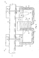
- the embodiment of Fig. 5 includes the bearing 28 surrounding the shaft 12 and defining the clearance 29, and the oil ring 32 positioned on the shaft.
- the bearing case 14, the bearing support 16, and the annular labyrinth seals 18 and 20 have been omitted in the interest of clarity, and the sump 38 has been replaced with a sump 50 which is also formed in the case 14 and which also receives the rotating oil ring 32.
- an external cooler 52 is provided for cooling the lubricant
- a conduit 62 is provided for circulating lubricant from the clearance 29 to the cooler 52.
- a slot and a port identical to the slot 42 and port 34, respectively of the embodiment of Figs. 1-4 are provided in the bearing 28 to transfer lubricant from the clearance 29 to the conduit 62.
- the cooler 52 is of conventional design, and, as such, includes an outer annular chamber 64 that contains cooling water and an inner reservoir portion 66 for receiving the lubricant.
- a conduit 68 connects the cooler 52 to the lower portion of the sump 50.
- a closed-loop lubricant circulation path P2 is defined that extends from the sump 50 to the oil ring 32, from the oil ring through the clearance 29, through the conduit 62, through the cooler 52, through the conduit 68, and back to the sump 50.
- lubricant is circulated from the sump 50 to the clearance 29, via the oil ring 32, in the same manner as described with reference to the embodiment of Figs. 1-4.
- the rotation of the shaft 12 generates enough pressure to drive the lubricant from the clearance 29 to the conduit 62.
- the lubricant flows from the conduit 62 to the cooler 52, where the lubricant collects and is cooled by the water in the chamber 64 prior to reentering the sump 50.
- the lubricant in the cooler 52 reaches a level that is greater than the level in the sump 50, the lubricant in the cooler circulates to the sump via the conduit 68, thereby completing circulation of the lubricant through the closed-loop lubricant circulation path P2.
- the embodiment of Fig. 6 includes the bearing assembly 10, including the bearing 28 surrounding the shaft 12 and defining the clearance 29, and the oil ring 32 positioned on the shaft.
- the bearing case 14, the bearing support 16, and the annular labyrinth seals 18 and 20 have been omitted in the interest of clarity, and the sump 38 has been replaced with a sump 80 which is also formed in the case 14 and which also receives the rotating oil ring 32.
- a bearing assembly 10' identical to the bearing assembly 10, is axially displaced from the bearing assembly 10.
- the bearing assembly 10' includes a bearing 28' surrounding the shaft 12 and defining a clearance (not depicted) and an oil ring 32' positioned on the shaft.
- the remaining portions of the bearing assembly 10' have been omitted in the interest of clarity and a sump 82 is defined in the case corresponding to the bearing assembly 10'.
- a single reservoir 84 is provided, and a conduit 86, depicted schematically in the interest of clarity, is provided for circulating lubricant from the clearance 29 to the sump 82.
- a conduit 88 also depicted schematically, is provided for circulating lubricant from the clearance associated with bearing assembly 10' to the sump 82. It is understood that, although not shown in Fig. 6, a slot and a port identical to the slot 42 and port 34, respectively of the embodiment of Figs. 1-4 are provided in the bearings 28 and 28' to transfer lubricant from the clearance 29 and the clearance associated with bearing assembly 10' to the conduits 86 and 88, respectively.
- a conduit 90 connects the sump 82 and the reservoir 84, with the end of the conduit 90 that extends into the sump 82 terminating at a sufficient height to act as a standpipe, thereby maintaining the lubricant level in the sump 82 at a greater height (represented by H1) than the lubricant levels in the reservoir 84 and the sump 80.
- a conduit 92 connects the sump 80 and the reservoir 84, with the end of the conduit 92 that extends into the reservoir 84 terminating at a sufficient height to act as a standpipe so that lubricant in the reservoir rising above the end of the conduit 92 will enter the conduit and circulate to the sump 80.
- the end of the conduit 92 that terminates in the sump 80 has a substantially equivalent height as the end of the same conduit that terminates in the reservoir 84, thereby maintaining substantially equivalent lubricant levels in the reservoir and the sump 80 for reasons to be described.
- the above-described arrangement defines a closed-loop lubricant circulation path P3 generally extending from the sump 80, to the oil ring 32, through the clearance 29, through the conduit 86, through the sump 82, through the conduit 90, through the reservoir 84, through the conduit 92, and back to the sump 80.
- lubricant is circulated from the sump 80 to the clearance 29 between the shaft 12 and the bearing 28 in the same manner as described with reference to the embodiment of Figs. 1-4.
- the rotation of the shaft 12. generates enough pressure to drive a portion of the lubricant from the clearance 29 to the conduit 86.
- the lubricant in the conduit 86 flows to the lower portion of sump 82 where the lubricant mixes with lubricant already in sump 82.
- Lubricant circulates from the sump 82 to the clearance associated with bearing assembly 10', via the oil ring 32', in the same manner as described with reference to Figs. 1-4.
- the rotation of the shaft 12 generates enough pressure to drive a portion of the lubricant from the clearance to the conduit 88 so that the lubricant flows through the conduit 88 to the sump 82.
- the sump 82 collects lubricant from both bearing assemblies 10 and 10', which causes the lubricant level of sump 82 to rise.
- the cost and size restraints normally associated with using one reservoir per bearing assembly are effectively eliminated. Furthermore, the extent of the circulation of the lubricant through the above-described arrangement ensures proper circulation of the lubricant without the use of a pump, thereby increasing the useful life of the lubricant, which in turn, reduces the wear and tear on the bearing assemblies 10, 10'.
- the lubricant circulation system according to the present invention may be applied to any arrangement involving a rotating member and a stationary member.
- the cooler 52 of the embodiment of Fig. 5 may alternatively be a reservoir and thus devoid of any cooling elements, and in a similar manner, the reservoir 84 (Fig. 6) may alternatively include cooling elements to provide for cooling of the lubricant being circulated therethrough. Still further, the cooler 52 and the reservoir 84 may include filters for cleaning the lubricant passing therethrough.
- references to specific structure of various elements of the bearing assemblies and the external cooler and reservoir are meant for example purposes only.
- various types of seals may be substituted for the labyrinth seals 18, 20 and the cooler 52 may alternatively employ cooling coils for cooling the lubricant passing therethrough.
- the bearing assemblies 10, 10' may be any type of ring-oiled bearing assemblies.
- conduits in the above-described lubricant circulation systems are not limited to a specific arrangement, and they may be attached to the various bearing assemblies in any conventional manner. Furthermore, in some embodiments, the conduits may be removed. Still further, the lubricant feed slot 42 may lead directly to the pressure lube feed port 34 (Fig. 4), and thus the port would not be radially displaced from the lubricant feed slot. If opposite rotation of the shaft 12 is desired, the lubricant feed slot 42 may be formed in an opposite portion of the bearing to collect lubricant drawn from the lubricant sump 38. Also, in some embodiments, the lubricant feed slot 42 may be omitted. Still further; the above spatial references, such as "radial,” “axial,” “upper,” and “lower” are for the purpose of illustration only and do not limit the specific orientation or location of the structure described above.
Landscapes
- Engineering & Computer Science (AREA)
- General Engineering & Computer Science (AREA)
- Mechanical Engineering (AREA)
- Chemical & Material Sciences (AREA)
- Combustion & Propulsion (AREA)
- Oil, Petroleum & Natural Gas (AREA)
- Rolling Contact Bearings (AREA)
Applications Claiming Priority (2)
| Application Number | Priority Date | Filing Date | Title |
|---|---|---|---|
| US726880 | 1996-10-04 | ||
| US10/726,880 US20050121263A1 (en) | 2003-12-03 | 2003-12-03 | Lubricant circulation system and method |
Publications (1)
| Publication Number | Publication Date |
|---|---|
| EP1538388A1 true EP1538388A1 (de) | 2005-06-08 |
Family
ID=34465758
Family Applications (1)
| Application Number | Title | Priority Date | Filing Date |
|---|---|---|---|
| EP04257396A Withdrawn EP1538388A1 (de) | 2003-12-03 | 2004-11-30 | Ölkreislauf-Verfahren und -Vorrichtung |
Country Status (3)
| Country | Link |
|---|---|
| US (1) | US20050121263A1 (de) |
| EP (1) | EP1538388A1 (de) |
| CA (1) | CA2488453A1 (de) |
Families Citing this family (3)
| Publication number | Priority date | Publication date | Assignee | Title |
|---|---|---|---|---|
| CA2645236A1 (en) * | 2008-11-03 | 2010-05-03 | Imad Hamad | Submersed turbine bearings |
| CN105485169B (zh) * | 2016-02-26 | 2017-09-01 | 绍兴文理学院 | 一种自润滑电机专用滑动轴承 |
| CN105485183B (zh) * | 2016-02-26 | 2018-03-27 | 绍兴文理学院 | 自润滑滑动轴承 |
Citations (4)
| Publication number | Priority date | Publication date | Assignee | Title |
|---|---|---|---|---|
| DE111968C (de) * | ||||
| DE461921C (de) * | 1928-06-28 | Oerlikon Maschf | Ringschmierlager | |
| US2280296A (en) * | 1940-06-14 | 1942-04-21 | American Brake Shoe & Foundry | Lubricating system for compressors or the like |
| US3499503A (en) * | 1967-03-31 | 1970-03-10 | Carrier Corp | Lubrication system |
Family Cites Families (5)
| Publication number | Priority date | Publication date | Assignee | Title |
|---|---|---|---|---|
| US3826338A (en) * | 1973-02-21 | 1974-07-30 | Ott A | Device for feeding a lubricating oil or the like to the periphery of a rotating element |
| US4531845A (en) * | 1984-01-09 | 1985-07-30 | Reliance Electric Company | Bearing lubrication device |
| US4591024A (en) * | 1984-03-19 | 1986-05-27 | Dresser Industries, Inc. | Lube oil ring pump |
| US5630481A (en) * | 1995-03-07 | 1997-05-20 | Tuthill Corporation | Radial sleeve bearing and associated lubrication system |
| US5601155A (en) * | 1995-07-05 | 1997-02-11 | Delaware Capital Formation, Inc. | Journal bearing using disk for transporting lubricant |
-
2003
- 2003-12-03 US US10/726,880 patent/US20050121263A1/en not_active Abandoned
-
2004
- 2004-11-24 CA CA002488453A patent/CA2488453A1/en not_active Abandoned
- 2004-11-30 EP EP04257396A patent/EP1538388A1/de not_active Withdrawn
Patent Citations (4)
| Publication number | Priority date | Publication date | Assignee | Title |
|---|---|---|---|---|
| DE111968C (de) * | ||||
| DE461921C (de) * | 1928-06-28 | Oerlikon Maschf | Ringschmierlager | |
| US2280296A (en) * | 1940-06-14 | 1942-04-21 | American Brake Shoe & Foundry | Lubricating system for compressors or the like |
| US3499503A (en) * | 1967-03-31 | 1970-03-10 | Carrier Corp | Lubrication system |
Non-Patent Citations (1)
| Title |
|---|
| ELWELL R C ET AL: "LUBRICATING JOURNAL BEARINGS WITH OIL RINGS", MACHINE DESIGN, PENTON,INC. CLEVELAND, US, vol. 61, no. 25, 7 December 1989 (1989-12-07), pages 111 - 115, XP000085124, ISSN: 0024-9114 * |
Also Published As
| Publication number | Publication date |
|---|---|
| US20050121263A1 (en) | 2005-06-09 |
| CA2488453A1 (en) | 2005-06-03 |
Similar Documents
| Publication | Publication Date | Title |
|---|---|---|
| EP0272151B1 (de) | Lager- und Schmiersystem für einen Turbolader | |
| AU2004201489B2 (en) | Diesel engine water pump with improved water seal | |
| CN102466026B (zh) | 轴装置 | |
| EP0573063B1 (de) | Lagerschmieranordnung für Rotationsmaschinen | |
| CN107031373B (zh) | 电机和机动车辆 | |
| JP4657121B2 (ja) | 車両用主電動機の軸受装置 | |
| EP0600559A1 (de) | Wälzkörper-Lageranordnung, versehen mit einer Filterdichtung | |
| EP0677672B1 (de) | Lagerschmierungsapparat für eine rotierende Maschine | |
| EP1471223B1 (de) | Wasserpumpe für Dieselmotor mit vorgespanntem Lager | |
| JP3548299B2 (ja) | 変速機の回転体支持構造 | |
| JPH05126141A (ja) | 多列ころ軸受用軸受ケーシング | |
| US4327950A (en) | Bearing and lubrication system | |
| AU2004201493B9 (en) | Diesel engine water pump with improved oil control | |
| WO1980001200A1 (en) | Centrifugal lubrication system for transmission pocket bearing | |
| EP1538388A1 (de) | Ölkreislauf-Verfahren und -Vorrichtung | |
| JP7760958B2 (ja) | 転がり軸受潤滑構造 | |
| JP2005221042A (ja) | 転がり軸受 | |
| JP2006022952A (ja) | 転がり軸受の潤滑構造 | |
| JP7453899B2 (ja) | 転がり軸受保持構造及びこれを使用する回転機械 | |
| EP1507328A2 (de) | Schmierungsanlage für eine rotierende Maschine | |
| EP0671567A1 (de) | Wälzlager | |
| US4243275A (en) | Bearing and lubrication system | |
| CN116670400B (zh) | 泵组 | |
| JP4527622B2 (ja) | 転がり軸受の潤滑装置 | |
| CN109818447B (zh) | 用于电机的端罩及其形成方法 |
Legal Events
| Date | Code | Title | Description |
|---|---|---|---|
| PUAI | Public reference made under article 153(3) epc to a published international application that has entered the european phase |
Free format text: ORIGINAL CODE: 0009012 |
|
| AK | Designated contracting states |
Kind code of ref document: A1 Designated state(s): AT BE BG CH CY CZ DE DK EE ES FI FR GB GR HU IE IS IT LI LU MC NL PL PT RO SE SI SK TR |
|
| AX | Request for extension of the european patent |
Extension state: AL HR LT LV MK YU |
|
| 17P | Request for examination filed |
Effective date: 20051104 |
|
| AKX | Designation fees paid |
Designated state(s): DE FR GB IT |
|
| 17Q | First examination report despatched |
Effective date: 20060126 |
|
| STAA | Information on the status of an ep patent application or granted ep patent |
Free format text: STATUS: THE APPLICATION IS DEEMED TO BE WITHDRAWN |
|
| 18D | Application deemed to be withdrawn |
Effective date: 20071225 |