EP1538448A1 - Wirbelstrom-Messaufnehmer - Google Patents
Wirbelstrom-Messaufnehmer Download PDFInfo
- Publication number
- EP1538448A1 EP1538448A1 EP04257422A EP04257422A EP1538448A1 EP 1538448 A1 EP1538448 A1 EP 1538448A1 EP 04257422 A EP04257422 A EP 04257422A EP 04257422 A EP04257422 A EP 04257422A EP 1538448 A1 EP1538448 A1 EP 1538448A1
- Authority
- EP
- European Patent Office
- Prior art keywords
- coil
- magnet
- pick
- path
- flux pattern
- Prior art date
- Legal status (The legal status is an assumption and is not a legal conclusion. Google has not performed a legal analysis and makes no representation as to the accuracy of the status listed.)
- Withdrawn
Links
- 230000005291 magnetic effect Effects 0.000 claims abstract description 22
- 230000004907 flux Effects 0.000 claims abstract description 17
- 230000001939 inductive effect Effects 0.000 claims abstract description 8
- 239000000696 magnetic material Substances 0.000 claims description 8
- 239000000523 sample Substances 0.000 abstract description 19
- 238000010276 construction Methods 0.000 description 2
- 230000004048 modification Effects 0.000 description 2
- 238000012986 modification Methods 0.000 description 2
- 230000035699 permeability Effects 0.000 description 2
- 238000006842 Henry reaction Methods 0.000 description 1
- 230000000694 effects Effects 0.000 description 1
- 230000005672 electromagnetic field Effects 0.000 description 1
- 239000002360 explosive Substances 0.000 description 1
- 230000005294 ferromagnetic effect Effects 0.000 description 1
- 239000002184 metal Substances 0.000 description 1
- 229910052751 metal Inorganic materials 0.000 description 1
- 239000000203 mixture Substances 0.000 description 1
- 229920006395 saturated elastomer Polymers 0.000 description 1
Images

Classifications
-
- F—MECHANICAL ENGINEERING; LIGHTING; HEATING; WEAPONS; BLASTING
- F01—MACHINES OR ENGINES IN GENERAL; ENGINE PLANTS IN GENERAL; STEAM ENGINES
- F01D—NON-POSITIVE DISPLACEMENT MACHINES OR ENGINES, e.g. STEAM TURBINES
- F01D17/00—Regulating or controlling by varying flow
- F01D17/02—Arrangement of sensing elements
- F01D17/06—Arrangement of sensing elements responsive to speed
-
- G—PHYSICS
- G01—MEASURING; TESTING
- G01P—MEASURING LINEAR OR ANGULAR SPEED, ACCELERATION, DECELERATION, OR SHOCK; INDICATING PRESENCE, ABSENCE, OR DIRECTION, OF MOVEMENT
- G01P3/00—Measuring linear or angular speed; Measuring differences of linear or angular speeds
- G01P3/42—Devices characterised by the use of electric or magnetic means
- G01P3/44—Devices characterised by the use of electric or magnetic means for measuring angular speed
- G01P3/49—Devices characterised by the use of electric or magnetic means for measuring angular speed using eddy currents
-
- F—MECHANICAL ENGINEERING; LIGHTING; HEATING; WEAPONS; BLASTING
- F05—INDEXING SCHEMES RELATING TO ENGINES OR PUMPS IN VARIOUS SUBCLASSES OF CLASSES F01-F04
- F05D—INDEXING SCHEME FOR ASPECTS RELATING TO NON-POSITIVE-DISPLACEMENT MACHINES OR ENGINES, GAS-TURBINES OR JET-PROPULSION PLANTS
- F05D2260/00—Function
- F05D2260/80—Diagnostics
Definitions
- This invention relates to eddy current sensors for sensing the movement of an electrically conductive member along a path.
- Such sensors are used as speed or torque sensing probes for example for sensing the speed of the blades of the compressor or turbine of a gas turbine.
- Torque in a rotating member may be assessed by using two sensing probes for sensing the rotation of the member at two axially-spaced positions and determining the phase difference between the outputs of the probes.
- the probe uses a strong and large magnet to form a strong magnetic field.
- a metal object such as a turbine blade passes through the field
- eddy currents are generated in the blade.
- the probe includes a pick-up coil for detecting the very small magnetic fields generated by the eddy currents induced in the tip of a moving blade.
- the coil needs to have a large number of turns, typically 5,000, wound on a core or pole piece made of a soft magnetic material having a high permeability.
- its inductance is very large, typically 1 or 2 henries.
- the probe is mounted outside on the turbine casing, resulting in a large air gap between the sensor and the tips of the blades.
- the magnetic field should be as strong as possible at the operating distance. This is achieved by selecting a very long wide magnet.
- the pick-up coil has to be as close to the magnet as possible to minimise space and to maximise the signal picked up.
- the magnetic field is attracted to the core of the pick-up coil so the strength of the field through which the blade tips pass is reduced.
- the portions of the blade passing at a distance of typically 10 to 12 mm from the magnet are not exposed to a strong magnetic field and the resulting eddy currents are weakened.
- the magnetic core of the coil increases the coil inductance resulting in a low resonance frequency and high impedance of the coil.
- the presence of resonance in the coil distorts the output signal amplitude of the probe.
- the signal may well have superimposed on it an oscillating signal resulting in several zero crossings giving a false speed reading.
- the current in a coil having a large inductance decays very slowly affecting the amplitude of the subsequent signals and changing the position of the zero crossings.
- sensors with coils having a large impedance are much more susceptible to electromagnetic interference.
- a sensor having a large inductance cannot be used in areas which must be intrinsically safe because the inductance stores a lot of energy and could generate a spark igniting an explosive gas mixture.
- the invention removes the conventional soft magnetic core from the probe coil.
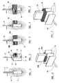
- Figure 1 shows a turbine blade 1, moving past a pole 2 of a magnet 3 (typically a permanent magnet) which generates a flux pattern indicated at 4.
- a magnet 3 typically a permanent magnet
- the flux pattern 4 extends well into the path of the turbine blade 1 with the result that eddy currents are generated in the turbine blade 1.
- FIG. 7 This arrangement is also shown in Fig. 7.
- the blades 21, 31 are compressor blades thus having thin and long cross-sections. Accordingly, the magnets 23, 33 and coils 28, 38 are elongated to conform to the general shape of the compressor blades 21, 31.
- the blades 41 are angled relative to their direction of travel 40 and the assembly of magnet 43 and pick-up coils 48a, b, is correspondingly angled.
- the body 61 has two further boxes 67a, 67b, one on each side of the pair of magnets 63, to receive the pick-up coils 68a, 68b.
- the cylindrical surface of the body 61 is formed with channels 69 leading to apertures 70 in the mounting flange 62 to receive the connecting wired for the coils.
- the probes shown in Figs. 3 to 10 may be used to measure the speed of any metallic non-ferromagnetic object with at least one discrete member such as the tooth of a gearwheel, a phonic wheel, a shaft with a slot or protrusion or the blades of a fan in which eddy currents are generated in the member as it rotates through the flux pattern.
- a discrete member such as the tooth of a gearwheel, a phonic wheel, a shaft with a slot or protrusion or the blades of a fan in which eddy currents are generated in the member as it rotates through the flux pattern.
- magnets will normally be permanent magnets for convenience, it would be possible to use electromagnets provided that they are fully saturated in use.
Landscapes
- Engineering & Computer Science (AREA)
- Mechanical Engineering (AREA)
- General Engineering & Computer Science (AREA)
- Physics & Mathematics (AREA)
- General Physics & Mathematics (AREA)
- Measurement Of Length, Angles, Or The Like Using Electric Or Magnetic Means (AREA)
- Structures Of Non-Positive Displacement Pumps (AREA)
- Investigating Or Analyzing Materials By The Use Of Magnetic Means (AREA)
- Transmission And Conversion Of Sensor Element Output (AREA)
Applications Claiming Priority (2)
| Application Number | Priority Date | Filing Date | Title |
|---|---|---|---|
| GB0328049 | 2003-12-03 | ||
| GB0328049A GB2408802A (en) | 2003-12-03 | 2003-12-03 | Eddy current sensors |
Publications (1)
| Publication Number | Publication Date |
|---|---|
| EP1538448A1 true EP1538448A1 (de) | 2005-06-08 |
Family
ID=29764519
Family Applications (1)
| Application Number | Title | Priority Date | Filing Date |
|---|---|---|---|
| EP04257422A Withdrawn EP1538448A1 (de) | 2003-12-03 | 2004-11-30 | Wirbelstrom-Messaufnehmer |
Country Status (4)
| Country | Link |
|---|---|
| US (1) | US20050127905A1 (de) |
| EP (1) | EP1538448A1 (de) |
| CA (1) | CA2488967A1 (de) |
| GB (1) | GB2408802A (de) |
Cited By (8)
| Publication number | Priority date | Publication date | Assignee | Title |
|---|---|---|---|---|
| WO2006059976A1 (en) * | 2004-12-01 | 2006-06-08 | United Technologies Corporation | Turbine engine with a rotor speed sensor and corresponding operating method |
| WO2010025017A1 (en) * | 2008-08-29 | 2010-03-04 | General Electric Company | System and method for sensing the periodic position of an object |
| WO2010025014A1 (en) * | 2008-08-29 | 2010-03-04 | General Electric Company | Variable reluctance sensor with noise elimination |
| FR2968038A1 (fr) * | 2010-11-26 | 2012-06-01 | Snecma | Systeme de detection d'un evenement fugace sur une roue aubagee de moteur d'aeronef |
| EP2728128A1 (de) * | 2012-10-31 | 2014-05-07 | Siemens Aktiengesellschaft | Messverfahren zur Schadenserkennung an einer Turbinenschaufel und Turbine |
| EP2749889A1 (de) * | 2012-12-28 | 2014-07-02 | Hanwha Corporation | Mündungsgeschwindigkeitsmessvorrichtung und Verfahren |
| WO2021014045A1 (es) | 2019-07-23 | 2021-01-28 | Piher Sensors & Controls, S.A. | Sistema sensor de posición |
| CN114450564A (zh) * | 2019-10-28 | 2022-05-06 | 三菱重工业株式会社 | 检测装置、旋转设备以及检测方法 |
Families Citing this family (54)
| Publication number | Priority date | Publication date | Assignee | Title |
|---|---|---|---|---|
| US7934902B2 (en) | 2004-12-01 | 2011-05-03 | United Technologies Corporation | Compressor variable stage remote actuation for turbine engine |
| WO2006110124A2 (en) * | 2004-12-01 | 2006-10-19 | United Technologies Corporation | Ejector cooling of outer case for tip turbine engine |
| US8087885B2 (en) * | 2004-12-01 | 2012-01-03 | United Technologies Corporation | Stacked annular components for turbine engines |
| US7959532B2 (en) | 2004-12-01 | 2011-06-14 | United Technologies Corporation | Hydraulic seal for a gearbox of a tip turbine engine |
| WO2006110122A2 (en) | 2004-12-01 | 2006-10-19 | United Technologies Corporation | Inflatable bleed valve for a turbine engine and a method of operating therefore |
| US7874163B2 (en) | 2004-12-01 | 2011-01-25 | United Technologies Corporation | Starter generator system for a tip turbine engine |
| WO2006059986A1 (en) | 2004-12-01 | 2006-06-08 | United Technologies Corporation | Tip turbine engine and operating method with reverse core airflow |
| US8061968B2 (en) | 2004-12-01 | 2011-11-22 | United Technologies Corporation | Counter-rotating compressor case and assembly method for tip turbine engine |
| DE602004020125D1 (de) | 2004-12-01 | 2009-04-30 | United Technologies Corp | Schmiermittel-versorgungssystem für das getriebe eines tip-turbinen-triebwerks |
| US8104257B2 (en) * | 2004-12-01 | 2012-01-31 | United Technologies Corporation | Tip turbine engine with multiple fan and turbine stages |
| EP1841959B1 (de) | 2004-12-01 | 2012-05-09 | United Technologies Corporation | Ausgewuchtete turbinenrotorlüfterschaufel für einen spitzenturbinenmotor |
| EP1828547B1 (de) | 2004-12-01 | 2011-11-30 | United Technologies Corporation | Turbofantriebwerk mit einer Mehrzahl von einzeln steuerbaren Einlassleitschaufeln und zugehöriges Steuerverfahren |
| EP1834067B1 (de) | 2004-12-01 | 2008-11-26 | United Technologies Corporation | Gebläseschaufelanordnung für ein tip-turbinentriebwerk und montageverfahren |
| WO2006060004A1 (en) | 2004-12-01 | 2006-06-08 | United Technologies Corporation | Combustor for turbine engine |
| EP1828545A2 (de) | 2004-12-01 | 2007-09-05 | United Technologies Corporation | Ringförmiger turbinenringrotor |
| WO2006059971A2 (en) | 2004-12-01 | 2006-06-08 | United Technologies Corporation | Tip turbine engine integral fan, combustor, and turbine case |
| EP1828574B1 (de) | 2004-12-01 | 2010-11-03 | United Technologies Corporation | Enggekoppelte getriebeanordnung für einen spitzenturbinenmotor |
| WO2006059980A2 (en) * | 2004-12-01 | 2006-06-08 | United Technologies Corporation | Diffuser aspiration for a tip turbine engine |
| DE602004031470D1 (de) * | 2004-12-01 | 2011-03-31 | United Technologies Corp | Übergangskanal mit mitteln zur strömungsvektorbeeinflussung bei einer gasturbine |
| WO2006060009A1 (en) | 2004-12-01 | 2006-06-08 | United Technologies Corporation | Turbine blade engine comprising turbine clusters and radial attachment lock arrangement therefor |
| EP1828591B1 (de) * | 2004-12-01 | 2010-07-21 | United Technologies Corporation | Umfangsbrennkammer für spitzenturbinenmotor |
| WO2006059978A1 (en) | 2004-12-01 | 2006-06-08 | United Technologies Corporation | Cantilevered tip turbine engine |
| WO2006060013A1 (en) | 2004-12-01 | 2006-06-08 | United Technologies Corporation | Seal assembly for a fan rotor of a tip turbine engine |
| WO2006059988A1 (en) | 2004-12-01 | 2006-06-08 | United Technologies Corporation | Modular tip turbine engine |
| US7887296B2 (en) | 2004-12-01 | 2011-02-15 | United Technologies Corporation | Fan blade with integral diffuser section and tip turbine blade section for a tip turbine engine |
| US20090148273A1 (en) * | 2004-12-01 | 2009-06-11 | Suciu Gabriel L | Compressor inlet guide vane for tip turbine engine and corresponding control method |
| WO2006060006A1 (en) | 2004-12-01 | 2006-06-08 | United Technologies Corporation | Tip turbine engine non-metallic tailcone |
| DE602004031986D1 (de) | 2004-12-01 | 2011-05-05 | United Technologies Corp | Gebläse-turbinen-rotoranordnung für einen spitzenturbinenmotor |
| WO2006059979A1 (en) | 2004-12-01 | 2006-06-08 | United Technologies Corporation | Tip turbine engine integral case, vane, mount, and mixer |
| EP1825113B1 (de) | 2004-12-01 | 2012-10-24 | United Technologies Corporation | Gegenläufiges getriebe für ein tip-turbinen-triebwerk |
| US9003759B2 (en) | 2004-12-01 | 2015-04-14 | United Technologies Corporation | Particle separator for tip turbine engine |
| US8561383B2 (en) | 2004-12-01 | 2013-10-22 | United Technologies Corporation | Turbine engine with differential gear driven fan and compressor |
| US7976273B2 (en) | 2004-12-01 | 2011-07-12 | United Technologies Corporation | Tip turbine engine support structure |
| WO2006059973A1 (en) * | 2004-12-01 | 2006-06-08 | United Technologies Corporation | Tip turbine engine with a heat exchanger |
| WO2006112807A2 (en) | 2004-12-01 | 2006-10-26 | United Technologies Corporation | Turbine engine and method for starting a turbine engine |
| WO2006059985A1 (en) | 2004-12-01 | 2006-06-08 | United Technologies Corporation | Axial compressor for tip turbine engine |
| WO2006059990A1 (en) | 2004-12-01 | 2006-06-08 | United Technologies Corporation | Regenerative turbine blade and vane cooling for a tip turbine engine |
| US8757959B2 (en) | 2004-12-01 | 2014-06-24 | United Technologies Corporation | Tip turbine engine comprising a nonrotable compartment |
| US7921636B2 (en) * | 2004-12-01 | 2011-04-12 | United Technologies Corporation | Tip turbine engine and corresponding operating method |
| US7883314B2 (en) | 2004-12-01 | 2011-02-08 | United Technologies Corporation | Seal assembly for a fan-turbine rotor of a tip turbine engine |
| DE602004016065D1 (de) | 2004-12-01 | 2008-10-02 | United Technologies Corp | Variable gebläseeinlassleitschaufelanordnung, turbinenmotor mit solch einer anordnung und entsprechendes steuerverfahren |
| US9109537B2 (en) | 2004-12-04 | 2015-08-18 | United Technologies Corporation | Tip turbine single plane mount |
| US20120210694A1 (en) * | 2007-04-11 | 2012-08-23 | Holmquist Eric B | Turbo machine spool parameter detection |
| US8967945B2 (en) | 2007-05-22 | 2015-03-03 | United Technologies Corporation | Individual inlet guide vane control for tip turbine engine |
| GB0712926D0 (en) * | 2007-07-04 | 2007-08-15 | Qinetiq Ltd | Eddy current sensors |
| DE102007051161A1 (de) * | 2007-10-25 | 2009-04-30 | Konrad Meß- und Regeltechnik GmbH | Wirbelstromsensoranordnung |
| GB2455798B (en) * | 2007-12-21 | 2010-04-28 | Weston Aerospace Ltd | Method and apparatus for monitoring a rotating shaft |
| CA2647306C (en) * | 2007-12-21 | 2018-09-04 | Weston Aerospace Limited | Method and apparatus for monitoring the rotational speed of a shaft |
| GB2455797B (en) | 2007-12-21 | 2010-04-28 | Weston Aerospace Ltd | Method and apparatus for monitoring the rotational speed of a shaft |
| GB2460697B (en) * | 2008-06-06 | 2010-09-29 | Weston Aerospace Ltd | High temperature speed or proximity sensor |
| PL210672B1 (pl) * | 2008-06-23 | 2012-02-29 | Inst Tech Wojsk Lotniczych | Czujnik indukcyjny do pomiaru drgań łopatki wirnika przepływowej maszyny wirnikowej |
| US8018225B2 (en) | 2008-11-25 | 2011-09-13 | General Electric Company | System and method for sensing the periodic position of an object |
| US9377328B2 (en) * | 2012-01-24 | 2016-06-28 | GM Global Technology Operations LLC | Variable reluctance sensor using spatially modulated magnetic fields |
| US11892469B2 (en) * | 2021-06-21 | 2024-02-06 | Rosemount Aerospace Inc. | Health-monitoring system for a device determining rotation frequency of a shaft |
Citations (2)
| Publication number | Priority date | Publication date | Assignee | Title |
|---|---|---|---|---|
| GB2265221A (en) * | 1992-03-21 | 1993-09-22 | Schlumberger Ind Ltd | Inductive sensors |
| DE19623236A1 (de) * | 1996-06-11 | 1997-12-18 | Horn E Dr Gmbh | Verfahren und Vorrichtung für die Drehzahlmessung an Turboladern |
Family Cites Families (13)
| Publication number | Priority date | Publication date | Assignee | Title |
|---|---|---|---|---|
| US3021711A (en) * | 1957-05-10 | 1962-02-20 | Svenska Flygmotor Aktiebolaget | Device for measuring pressure or difference of pressure in fluids |
| US3119355A (en) * | 1959-10-23 | 1964-01-28 | Verband Deutscher Konsumgenoss | Apparatus for the baking of bread and other bakery products with infra-red rays |
| GB1226149A (de) * | 1967-10-09 | 1971-03-24 | ||
| CA984463A (en) * | 1972-04-20 | 1976-02-24 | Simmonds Precision Products | Eddy current sensor |
| US3863505A (en) * | 1973-07-09 | 1975-02-04 | United Aircraft Corp | Vibrating cylinder pressure transducer |
| US3984713A (en) * | 1975-04-04 | 1976-10-05 | The Bendix Corporation | Magnetic speed sensor with compensating pole |
| US4102209A (en) * | 1977-06-17 | 1978-07-25 | United Technologies Corporation | Temperature compensated vibrating cylinder pressure transducer |
| DE3411773C2 (de) * | 1984-03-30 | 1987-02-12 | Daimler-Benz Ag, 7000 Stuttgart | Vorrichtung zur Erfassung der Drehzahl und/oder eines Drehwinkels einer Welle |
| US4967153A (en) * | 1986-09-08 | 1990-10-30 | Langley Lawrence W | Eddy current turbomachinery blade timing system |
| CH690934A5 (fr) * | 1996-04-29 | 2001-02-28 | Suisse Electronique Microtech | Dispositif de détection de position et de mouvement à variation de champ magnétique. |
| DE10032143C2 (de) * | 1999-09-30 | 2002-07-18 | Heidenhain Gmbh Dr Johannes | Ferraris-Sensor und Verfahren zum Betrieb eines Ferraris-Sensors |
| DE10118650A1 (de) * | 2001-04-14 | 2002-10-17 | Philips Corp Intellectual Pty | Winkelsensor sowie Verfahren zum Erhöhen der Anisotropiefeldstärke einer Sensoreinheit eines Winkelsensors |
| DE10216635B4 (de) * | 2002-04-15 | 2008-03-13 | Siemens Ag | Bewegungsdetektor nach dem Ferrarisprinzip |
-
2003
- 2003-12-03 GB GB0328049A patent/GB2408802A/en not_active Withdrawn
-
2004
- 2004-11-30 EP EP04257422A patent/EP1538448A1/de not_active Withdrawn
- 2004-12-02 CA CA002488967A patent/CA2488967A1/en not_active Abandoned
- 2004-12-03 US US11/002,990 patent/US20050127905A1/en not_active Abandoned
Patent Citations (2)
| Publication number | Priority date | Publication date | Assignee | Title |
|---|---|---|---|---|
| GB2265221A (en) * | 1992-03-21 | 1993-09-22 | Schlumberger Ind Ltd | Inductive sensors |
| DE19623236A1 (de) * | 1996-06-11 | 1997-12-18 | Horn E Dr Gmbh | Verfahren und Vorrichtung für die Drehzahlmessung an Turboladern |
Cited By (18)
| Publication number | Priority date | Publication date | Assignee | Title |
|---|---|---|---|---|
| WO2006059976A1 (en) * | 2004-12-01 | 2006-06-08 | United Technologies Corporation | Turbine engine with a rotor speed sensor and corresponding operating method |
| WO2010025017A1 (en) * | 2008-08-29 | 2010-03-04 | General Electric Company | System and method for sensing the periodic position of an object |
| WO2010025014A1 (en) * | 2008-08-29 | 2010-03-04 | General Electric Company | Variable reluctance sensor with noise elimination |
| GB2476183A (en) * | 2008-08-29 | 2011-06-15 | Gen Electric | Variable reluctance sensor with noise elimination |
| GB2476184A (en) * | 2008-08-29 | 2011-06-15 | Gen Electric | System and method for sensing the periodic position of an object |
| GB2476184B (en) * | 2008-08-29 | 2012-05-02 | Gen Electric | System and method for sensing the periodic position of an object |
| GB2476183B (en) * | 2008-08-29 | 2012-08-22 | Gen Electric | Variable reluctance sensor with noise elimination |
| US10487683B2 (en) | 2010-11-26 | 2019-11-26 | Safran Aircraft Engines | System for detecting an ephemeral event on a vane impeller of an aircraft engine |
| FR2968038A1 (fr) * | 2010-11-26 | 2012-06-01 | Snecma | Systeme de detection d'un evenement fugace sur une roue aubagee de moteur d'aeronef |
| EP2728128A1 (de) * | 2012-10-31 | 2014-05-07 | Siemens Aktiengesellschaft | Messverfahren zur Schadenserkennung an einer Turbinenschaufel und Turbine |
| US9804110B2 (en) | 2012-10-31 | 2017-10-31 | Siemens Aktiengesellschaft | Measurement method for detecting damage to a turbine blade and turbine |
| WO2014067737A1 (de) * | 2012-10-31 | 2014-05-08 | Siemens Aktiengesellschaft | Messverfahren zur schadenserkennung an einer turbinenschaufel und turbine |
| EP2749889A1 (de) * | 2012-12-28 | 2014-07-02 | Hanwha Corporation | Mündungsgeschwindigkeitsmessvorrichtung und Verfahren |
| US9513308B2 (en) | 2012-12-28 | 2016-12-06 | Hanwha Corporation | Muzzle velocity measuring apparatus and method |
| WO2021014045A1 (es) | 2019-07-23 | 2021-01-28 | Piher Sensors & Controls, S.A. | Sistema sensor de posición |
| CN113661371A (zh) * | 2019-07-23 | 2021-11-16 | 比尔传感和控制公司 | 位置传感器系统 |
| CN114450564A (zh) * | 2019-10-28 | 2022-05-06 | 三菱重工业株式会社 | 检测装置、旋转设备以及检测方法 |
| CN114450564B (zh) * | 2019-10-28 | 2024-04-30 | 三菱重工业株式会社 | 检测装置、旋转设备以及检测方法 |
Also Published As
| Publication number | Publication date |
|---|---|
| CA2488967A1 (en) | 2005-06-03 |
| US20050127905A1 (en) | 2005-06-16 |
| GB0328049D0 (en) | 2004-01-07 |
| GB2408802A (en) | 2005-06-08 |
Similar Documents
| Publication | Publication Date | Title |
|---|---|---|
| US20050127905A1 (en) | Eddy current sensors | |
| US4045738A (en) | Variable reluctance speed sensor of integral construction utilizing a shielded high coercive force rare earth magnet positioned directly adjacent the sensing rotating element | |
| US5528139A (en) | Magnetic position and speed sensor with hall probe in an air gap | |
| US7023205B1 (en) | Eddy current sensor capable of sensing through a conductive barrier | |
| US4751459A (en) | Magnetic tachometer or accelerometer having highly permeable eddy current flux circuit | |
| US5814985A (en) | Incremental sensor of speed and/or position for detecting low and null speeds | |
| US6850053B2 (en) | Device for measuring the motion of a conducting body through magnetic induction | |
| US3932813A (en) | Eddy current sensor | |
| US4229696A (en) | Sensor for measuring magnetic field changes | |
| KR920006499B1 (ko) | 토오크 센서 | |
| US4384252A (en) | Cup shaped magnetic pickoff for use with a variable reluctance motion sensing system | |
| GB2265221A (en) | Inductive sensors | |
| WO2009034305A2 (en) | Rotor blade sensor | |
| JP6559629B2 (ja) | 外部浮遊磁場を補償する装置または磁場勾配が磁場センサに及ぼす影響を補償する装置 | |
| EP0362882B1 (de) | Magnetlager | |
| WO2013060601A1 (en) | Magnetic flux enhancer system for reluctance type sensors | |
| US6927567B1 (en) | Passive eddy current blade detection sensor | |
| US20030155911A1 (en) | Tunable magnetic device for use in a proximity sensor | |
| JP2000161989A (ja) | 回転センサ | |
| US5373234A (en) | Inductive speed or torque sensor with compensation for external magnetic fields | |
| US7148679B2 (en) | Transformer probe | |
| US20030048100A1 (en) | Magnetic sensor of the position of a moving member over a trajectory followed by the moving member | |
| CA2593553A1 (en) | Aerospace movement probe | |
| JP2017129431A (ja) | 近接センサ | |
| GB2231161A (en) | Improvements relating to rotary position transducers |
Legal Events
| Date | Code | Title | Description |
|---|---|---|---|
| PUAI | Public reference made under article 153(3) epc to a published international application that has entered the european phase |
Free format text: ORIGINAL CODE: 0009012 |
|
| AK | Designated contracting states |
Kind code of ref document: A1 Designated state(s): AT BE BG CH CY CZ DE DK EE ES FI FR GB GR HU IE IS IT LI LU MC NL PL PT RO SE SI SK TR |
|
| AX | Request for extension of the european patent |
Extension state: AL HR LT LV MK YU |
|
| 17P | Request for examination filed |
Effective date: 20051103 |
|
| AKX | Designation fees paid |
Designated state(s): DE FR GB IT |
|
| STAA | Information on the status of an ep patent application or granted ep patent |
Free format text: STATUS: THE APPLICATION IS DEEMED TO BE WITHDRAWN |
|
| 18D | Application deemed to be withdrawn |
Effective date: 20060829 |