EP1538589A2 - Verfahren zur Steuerung einer Plasmaanzeigevorrichtung - Google Patents
Verfahren zur Steuerung einer Plasmaanzeigevorrichtung Download PDFInfo
- Publication number
- EP1538589A2 EP1538589A2 EP04090460A EP04090460A EP1538589A2 EP 1538589 A2 EP1538589 A2 EP 1538589A2 EP 04090460 A EP04090460 A EP 04090460A EP 04090460 A EP04090460 A EP 04090460A EP 1538589 A2 EP1538589 A2 EP 1538589A2
- Authority
- EP
- European Patent Office
- Prior art keywords
- electrode
- period
- sustain discharge
- sustain
- subfield
- Prior art date
- Legal status (The legal status is an assumption and is not a legal conclusion. Google has not performed a legal analysis and makes no representation as to the accuracy of the status listed.)
- Withdrawn
Links
Images


Classifications
-
- G—PHYSICS
- G09—EDUCATION; CRYPTOGRAPHY; DISPLAY; ADVERTISING; SEALS
- G09G—ARRANGEMENTS OR CIRCUITS FOR CONTROL OF INDICATING DEVICES USING STATIC MEANS TO PRESENT VARIABLE INFORMATION
- G09G3/00—Control arrangements or circuits, of interest only in connection with visual indicators other than cathode-ray tubes
- G09G3/20—Control arrangements or circuits, of interest only in connection with visual indicators other than cathode-ray tubes for presentation of an assembly of a number of characters, e.g. a page, by composing the assembly by combination of individual elements arranged in a matrix no fixed position being assigned to or needed to be assigned to the individual characters or partial characters
- G09G3/22—Control arrangements or circuits, of interest only in connection with visual indicators other than cathode-ray tubes for presentation of an assembly of a number of characters, e.g. a page, by composing the assembly by combination of individual elements arranged in a matrix no fixed position being assigned to or needed to be assigned to the individual characters or partial characters using controlled light sources
- G09G3/28—Control arrangements or circuits, of interest only in connection with visual indicators other than cathode-ray tubes for presentation of an assembly of a number of characters, e.g. a page, by composing the assembly by combination of individual elements arranged in a matrix no fixed position being assigned to or needed to be assigned to the individual characters or partial characters using controlled light sources using luminous gas-discharge panels, e.g. plasma panels
- G09G3/288—Control arrangements or circuits, of interest only in connection with visual indicators other than cathode-ray tubes for presentation of an assembly of a number of characters, e.g. a page, by composing the assembly by combination of individual elements arranged in a matrix no fixed position being assigned to or needed to be assigned to the individual characters or partial characters using controlled light sources using luminous gas-discharge panels, e.g. plasma panels using AC panels
- G09G3/291—Control arrangements or circuits, of interest only in connection with visual indicators other than cathode-ray tubes for presentation of an assembly of a number of characters, e.g. a page, by composing the assembly by combination of individual elements arranged in a matrix no fixed position being assigned to or needed to be assigned to the individual characters or partial characters using controlled light sources using luminous gas-discharge panels, e.g. plasma panels using AC panels controlling the gas discharge to control a cell condition, e.g. by means of specific pulse shapes
-
- G—PHYSICS
- G09—EDUCATION; CRYPTOGRAPHY; DISPLAY; ADVERTISING; SEALS
- G09G—ARRANGEMENTS OR CIRCUITS FOR CONTROL OF INDICATING DEVICES USING STATIC MEANS TO PRESENT VARIABLE INFORMATION
- G09G3/00—Control arrangements or circuits, of interest only in connection with visual indicators other than cathode-ray tubes
- G09G3/20—Control arrangements or circuits, of interest only in connection with visual indicators other than cathode-ray tubes for presentation of an assembly of a number of characters, e.g. a page, by composing the assembly by combination of individual elements arranged in a matrix no fixed position being assigned to or needed to be assigned to the individual characters or partial characters
- G09G3/2007—Display of intermediate tones
- G09G3/2018—Display of intermediate tones by time modulation using two or more time intervals
- G09G3/2022—Display of intermediate tones by time modulation using two or more time intervals using sub-frames
-
- G—PHYSICS
- G09—EDUCATION; CRYPTOGRAPHY; DISPLAY; ADVERTISING; SEALS
- G09G—ARRANGEMENTS OR CIRCUITS FOR CONTROL OF INDICATING DEVICES USING STATIC MEANS TO PRESENT VARIABLE INFORMATION
- G09G3/00—Control arrangements or circuits, of interest only in connection with visual indicators other than cathode-ray tubes
- G09G3/20—Control arrangements or circuits, of interest only in connection with visual indicators other than cathode-ray tubes for presentation of an assembly of a number of characters, e.g. a page, by composing the assembly by combination of individual elements arranged in a matrix no fixed position being assigned to or needed to be assigned to the individual characters or partial characters
- G09G3/22—Control arrangements or circuits, of interest only in connection with visual indicators other than cathode-ray tubes for presentation of an assembly of a number of characters, e.g. a page, by composing the assembly by combination of individual elements arranged in a matrix no fixed position being assigned to or needed to be assigned to the individual characters or partial characters using controlled light sources
- G09G3/28—Control arrangements or circuits, of interest only in connection with visual indicators other than cathode-ray tubes for presentation of an assembly of a number of characters, e.g. a page, by composing the assembly by combination of individual elements arranged in a matrix no fixed position being assigned to or needed to be assigned to the individual characters or partial characters using controlled light sources using luminous gas-discharge panels, e.g. plasma panels
- G09G3/288—Control arrangements or circuits, of interest only in connection with visual indicators other than cathode-ray tubes for presentation of an assembly of a number of characters, e.g. a page, by composing the assembly by combination of individual elements arranged in a matrix no fixed position being assigned to or needed to be assigned to the individual characters or partial characters using controlled light sources using luminous gas-discharge panels, e.g. plasma panels using AC panels
- G09G3/291—Control arrangements or circuits, of interest only in connection with visual indicators other than cathode-ray tubes for presentation of an assembly of a number of characters, e.g. a page, by composing the assembly by combination of individual elements arranged in a matrix no fixed position being assigned to or needed to be assigned to the individual characters or partial characters using controlled light sources using luminous gas-discharge panels, e.g. plasma panels using AC panels controlling the gas discharge to control a cell condition, e.g. by means of specific pulse shapes
- G09G3/292—Control arrangements or circuits, of interest only in connection with visual indicators other than cathode-ray tubes for presentation of an assembly of a number of characters, e.g. a page, by composing the assembly by combination of individual elements arranged in a matrix no fixed position being assigned to or needed to be assigned to the individual characters or partial characters using controlled light sources using luminous gas-discharge panels, e.g. plasma panels using AC panels controlling the gas discharge to control a cell condition, e.g. by means of specific pulse shapes for reset discharge, priming discharge or erase discharge occurring in a phase other than addressing
- G09G3/2927—Details of initialising
-
- G—PHYSICS
- G09—EDUCATION; CRYPTOGRAPHY; DISPLAY; ADVERTISING; SEALS
- G09G—ARRANGEMENTS OR CIRCUITS FOR CONTROL OF INDICATING DEVICES USING STATIC MEANS TO PRESENT VARIABLE INFORMATION
- G09G3/00—Control arrangements or circuits, of interest only in connection with visual indicators other than cathode-ray tubes
- G09G3/20—Control arrangements or circuits, of interest only in connection with visual indicators other than cathode-ray tubes for presentation of an assembly of a number of characters, e.g. a page, by composing the assembly by combination of individual elements arranged in a matrix no fixed position being assigned to or needed to be assigned to the individual characters or partial characters
- G09G3/22—Control arrangements or circuits, of interest only in connection with visual indicators other than cathode-ray tubes for presentation of an assembly of a number of characters, e.g. a page, by composing the assembly by combination of individual elements arranged in a matrix no fixed position being assigned to or needed to be assigned to the individual characters or partial characters using controlled light sources
- G09G3/28—Control arrangements or circuits, of interest only in connection with visual indicators other than cathode-ray tubes for presentation of an assembly of a number of characters, e.g. a page, by composing the assembly by combination of individual elements arranged in a matrix no fixed position being assigned to or needed to be assigned to the individual characters or partial characters using controlled light sources using luminous gas-discharge panels, e.g. plasma panels
- G09G3/288—Control arrangements or circuits, of interest only in connection with visual indicators other than cathode-ray tubes for presentation of an assembly of a number of characters, e.g. a page, by composing the assembly by combination of individual elements arranged in a matrix no fixed position being assigned to or needed to be assigned to the individual characters or partial characters using controlled light sources using luminous gas-discharge panels, e.g. plasma panels using AC panels
- G09G3/291—Control arrangements or circuits, of interest only in connection with visual indicators other than cathode-ray tubes for presentation of an assembly of a number of characters, e.g. a page, by composing the assembly by combination of individual elements arranged in a matrix no fixed position being assigned to or needed to be assigned to the individual characters or partial characters using controlled light sources using luminous gas-discharge panels, e.g. plasma panels using AC panels controlling the gas discharge to control a cell condition, e.g. by means of specific pulse shapes
- G09G3/294—Control arrangements or circuits, of interest only in connection with visual indicators other than cathode-ray tubes for presentation of an assembly of a number of characters, e.g. a page, by composing the assembly by combination of individual elements arranged in a matrix no fixed position being assigned to or needed to be assigned to the individual characters or partial characters using controlled light sources using luminous gas-discharge panels, e.g. plasma panels using AC panels controlling the gas discharge to control a cell condition, e.g. by means of specific pulse shapes for lighting or sustain discharge
-
- G—PHYSICS
- G09—EDUCATION; CRYPTOGRAPHY; DISPLAY; ADVERTISING; SEALS
- G09G—ARRANGEMENTS OR CIRCUITS FOR CONTROL OF INDICATING DEVICES USING STATIC MEANS TO PRESENT VARIABLE INFORMATION
- G09G3/00—Control arrangements or circuits, of interest only in connection with visual indicators other than cathode-ray tubes
- G09G3/20—Control arrangements or circuits, of interest only in connection with visual indicators other than cathode-ray tubes for presentation of an assembly of a number of characters, e.g. a page, by composing the assembly by combination of individual elements arranged in a matrix no fixed position being assigned to or needed to be assigned to the individual characters or partial characters
- G09G3/22—Control arrangements or circuits, of interest only in connection with visual indicators other than cathode-ray tubes for presentation of an assembly of a number of characters, e.g. a page, by composing the assembly by combination of individual elements arranged in a matrix no fixed position being assigned to or needed to be assigned to the individual characters or partial characters using controlled light sources
- G09G3/28—Control arrangements or circuits, of interest only in connection with visual indicators other than cathode-ray tubes for presentation of an assembly of a number of characters, e.g. a page, by composing the assembly by combination of individual elements arranged in a matrix no fixed position being assigned to or needed to be assigned to the individual characters or partial characters using controlled light sources using luminous gas-discharge panels, e.g. plasma panels
- G09G3/288—Control arrangements or circuits, of interest only in connection with visual indicators other than cathode-ray tubes for presentation of an assembly of a number of characters, e.g. a page, by composing the assembly by combination of individual elements arranged in a matrix no fixed position being assigned to or needed to be assigned to the individual characters or partial characters using controlled light sources using luminous gas-discharge panels, e.g. plasma panels using AC panels
- G09G3/296—Driving circuits for producing the waveforms applied to the driving electrodes
-
- G—PHYSICS
- G09—EDUCATION; CRYPTOGRAPHY; DISPLAY; ADVERTISING; SEALS
- G09G—ARRANGEMENTS OR CIRCUITS FOR CONTROL OF INDICATING DEVICES USING STATIC MEANS TO PRESENT VARIABLE INFORMATION
- G09G3/00—Control arrangements or circuits, of interest only in connection with visual indicators other than cathode-ray tubes
- G09G3/20—Control arrangements or circuits, of interest only in connection with visual indicators other than cathode-ray tubes for presentation of an assembly of a number of characters, e.g. a page, by composing the assembly by combination of individual elements arranged in a matrix no fixed position being assigned to or needed to be assigned to the individual characters or partial characters
- G09G3/22—Control arrangements or circuits, of interest only in connection with visual indicators other than cathode-ray tubes for presentation of an assembly of a number of characters, e.g. a page, by composing the assembly by combination of individual elements arranged in a matrix no fixed position being assigned to or needed to be assigned to the individual characters or partial characters using controlled light sources
- G09G3/28—Control arrangements or circuits, of interest only in connection with visual indicators other than cathode-ray tubes for presentation of an assembly of a number of characters, e.g. a page, by composing the assembly by combination of individual elements arranged in a matrix no fixed position being assigned to or needed to be assigned to the individual characters or partial characters using controlled light sources using luminous gas-discharge panels, e.g. plasma panels
- G09G3/288—Control arrangements or circuits, of interest only in connection with visual indicators other than cathode-ray tubes for presentation of an assembly of a number of characters, e.g. a page, by composing the assembly by combination of individual elements arranged in a matrix no fixed position being assigned to or needed to be assigned to the individual characters or partial characters using controlled light sources using luminous gas-discharge panels, e.g. plasma panels using AC panels
- G09G3/298—Control arrangements or circuits, of interest only in connection with visual indicators other than cathode-ray tubes for presentation of an assembly of a number of characters, e.g. a page, by composing the assembly by combination of individual elements arranged in a matrix no fixed position being assigned to or needed to be assigned to the individual characters or partial characters using controlled light sources using luminous gas-discharge panels, e.g. plasma panels using AC panels using surface discharge panels
- G09G3/2983—Control arrangements or circuits, of interest only in connection with visual indicators other than cathode-ray tubes for presentation of an assembly of a number of characters, e.g. a page, by composing the assembly by combination of individual elements arranged in a matrix no fixed position being assigned to or needed to be assigned to the individual characters or partial characters using controlled light sources using luminous gas-discharge panels, e.g. plasma panels using AC panels using surface discharge panels using non-standard pixel electrode arrangements
- G09G3/2986—Control arrangements or circuits, of interest only in connection with visual indicators other than cathode-ray tubes for presentation of an assembly of a number of characters, e.g. a page, by composing the assembly by combination of individual elements arranged in a matrix no fixed position being assigned to or needed to be assigned to the individual characters or partial characters using controlled light sources using luminous gas-discharge panels, e.g. plasma panels using AC panels using surface discharge panels using non-standard pixel electrode arrangements with more than 3 electrodes involved in the operation
-
- G—PHYSICS
- G09—EDUCATION; CRYPTOGRAPHY; DISPLAY; ADVERTISING; SEALS
- G09G—ARRANGEMENTS OR CIRCUITS FOR CONTROL OF INDICATING DEVICES USING STATIC MEANS TO PRESENT VARIABLE INFORMATION
- G09G2310/00—Command of the display device
- G09G2310/06—Details of flat display driving waveforms
- G09G2310/066—Waveforms comprising a gently increasing or decreasing portion, e.g. ramp
Definitions
- the present invention relates to a plasma display panel (PDP) driving method. More specifically, the present invention relates to a PDP driving method for improving gray scale representation performance and gray scale linearity.
- PDP plasma display panel
- LCDs liquid crystal displays
- FEDs field emission displays
- plasma displays have better luminance and light emission efficiency as compared to the other types of flat panel devices, and also have wider view angles. Therefore, the plasma displays have come into the spotlight as substitutes for the conventional cathode ray tubes (CRTs) in large displays of greater than 40 inches.
- CTRs cathode ray tubes
- the plasma display is a flat display that uses plasma generated via a gas discharge process to display characters or images.
- the plasma display can include tens to millions of pixels that are provided thereon in a matrix format.
- plasma displays can be categorized into direct current (DC) plasma displays and alternating current (AC) plasma displays.
- the DC plasma displays have electrodes exposed in the discharge space without insulation, they allow a current to flow in the discharge space while the voltage is supplied, and therefore they are problematic in that they require resistors for current restriction.
- the AC plasma displays have electrodes covered by a dielectric layer, capacitances are naturally formed to restrict the current, and the electrodes are protected from ion shocks in the case of discharging. Accordingly, the AC plasma displays have a longer lifespan than the DC plasma displays.
- FIG. 1 shows a partial perspective view of an AC PDP
- FIG. 2 shows a cross-sectional view of the PDP shown in FIG. 1.
- X electrode 3 and Y electrode 4 made of transparent conductive matter and disposed over dielectric layer 14 and protection film 15, are provided in parallel and form a pair with each other under first glass substrate 11.
- Metallic bus electrodes 6 are respectively formed on the surfaces of X and Y electrodes 3 and 4.
- a plurality of address electrodes 5 covered with dielectric layer 14' are installed on second glass substrate 12.
- Barrier ribs 17 are formed on dielectric layer 14' between address electrodes 5, and in parallel with address electrodes 5.
- Phosphors 18 are formed on the surface of dielectric layer 14' between barrier ribs 17.
- First and second glass substrates 11,12 are provided facing each other with a discharge space 19 between first and second glass substrates 11, 12 so that Y electrode 4 and the X electrode 3 may respectively cross address electrodes 5.
- An address electrode of the address electrode 5 and discharge space 19 formed at a crossing part of Y electrode 4 and X electrode 3 form schematically indicated discharge cell 20.
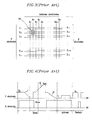
- FIG. 3 shows a conventional PDP electrode arrangement diagram.
- the conventional PDP electrodes have an m x n matrix configuration. Address electrodes A 1 to A m are arranged in a column direction, and Y electrodes Y 1 to Y n and X electrodes X 1 to X n are alternately arranged in a row direction.
- Discharge cell 20 shown in FIG. 3 substantially corresponds to the discharge cell 20 shown in FIG. 1.
- FIG. 4 shows a conventional PDP driving waveform diagram.
- a conventional PDP one frame is divided into a plurality of subfields that are combined to express a gray scale.
- Each subfield according to the conventional PDP method shown in FIG. 4 includes a reset period, an address period, and a sustain period.
- the reset period erases wall charges formed during a previous sustain discharge, and sets up new wall charges in order to stably perform functions in a next address period.
- the addressing period the cells that are turned on and the cells that are not turned on in a panel are selected, and wall charges are accumulated on the cells that are turned on (i.e., the addressed cells).
- the sustain period discharge for actually displaying pictures on the addressed cells is performed by alternately applying a sustain discharge voltage to the X and Y electrodes.
- the reset period includes an erase period (I), a Y ramp rising period (II), and a Y ramp falling period (III).
- the address electrode (not shown) and the X electrode are maintained at 0V, and a ramp voltage gradually rising from the voltage of Vs to the voltage of Vset is applied to the Y electrode. While the ramp voltage rises, a weak reset discharge is generated on all the discharge cells from the Y electrode to the address electrode and the X electrode. As a result, the (-) wall charges are accumulated on the Y electrode, and concurrently, the (+) wall charges are accumulated on the address electrode and the X electrode.
- the same sustain discharge voltage Vs is alternately applied to the X and Y electrodes to perform a sustain discharge for displaying actual images on the addressed cells.
- a circuit for driving the Y electrode is different from a circuit for driving the X electrode since a waveform applied to the Y electrode (a waveform for resetting and scanning is additionally applied to the Y electrode) is different from a waveform applied to the X electrode in the reset period of the conventional PDP. Accordingly, the driving circuits of the X and Y electrodes are not impedance-matched, the waveform alternately applied to the X and Y electrodes in the sustain discharge period is distorted, and a bad discharge is generated.
- a bad (or weak) discharge may be generated due to insufficient priming particles generated in the discharge cell when the first (or initial) sustain discharge pulse is applied after the address period in the conventional PDP.
- one frame e.g., one TV field
- the subfields are controlled by time division to thus represent gray scales.
- Each subfield includes a reset period, an address period, and a sustain discharge period.
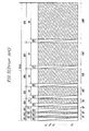
- FIG. 5 illustrates a case in which a frame (or a TV field) is divided into eight subfields in order to realize 256 gray scales.
- the respective subfields SF1 to SF8 each includes a reset period (not shown), a respective address period A1, A2, A3, A4, A5, A6, A7, and A8, and a respective sustain discharge period S1, S2, S3, S4, S5, S6, S7, and S8.
- Sustain discharge periods S1, S2, S3, S4, S5, S6, S7, S8 have light emission periods 1T, 2T, 4T, 8T, 16T, 32T, 64T, 128T with load ratios or weights of 1:2:4:8:16:32:64:128.
- discharge cells are controlled to be discharged in the subfield SF1 with a light emission period of 1T and the subfield SF2 with a light emission period of 2T so that the summation of the discharged periods may become 3T.
- the subfields with different light emission periods are combined to represent the video with 256 gray scales.
- sustain discharge pulses are respectively applied to the X and Y electrodes during the sustain period, and the gray scales are represented according to the corresponding number of sustain discharge pulses. That is, the gray scales are represented by combination of the numbers of the sustain discharge pulses applied to the respective subfields.
- a conventional PDP driving method shown in FIG. 5 shows a conventional PDP driving method shown in FIG.
- Two sustain discharge pulses are required for the addition or elimination and it is impossible to add or eliminate just one sustain discharge pulse because the sustain discharge pulses are alternately applied to the X and Y electrodes and the final sustain discharge pulse is applied to the Y electrode. That is, the normal reset process can be performed in the subsequent reset period only when the negative wall charges are accumulated on the Y electrode by the final sustain discharge pulse of the sustain period and the positive wall charges are maintained at the X electrode (which is biased with a ground voltage or a voltage lower than Vs).
- a method for driving a PDP includes a first electrode and a second electrode to which a sustain discharge pulse is applied respectively, and a third electrode formed between the first and second electrodes, wherein one field of the PDP is divided into a plurality of subfields, the subfields are then driven, and each subfield includes a reset period, an address period, and a sustain period.
- the method includes: (a) applying a scan pulse voltage to the third electrode during the address period; and (b) applying a sustain discharge pulse voltage to one of the first and second electrodes during the sustain period, wherein the subfields comprise at least one first subfield for applying a final sustain discharge pulse of the sustain period to the first electrode and at least one second subfield for applying the final sustain discharge pulse of the sustain period to the second electrode.
- a method for driving a PDP includes a first electrode and a second electrode to which a sustain discharge pulse is applied respectively, and a third electrode formed between the first and second electrodes, wherein one field of the PDP is divided into a plurality of subfields, the subfields are then driven, and each subfield includes a reset period, an address period, and a sustain period.
- the method includes: (a) applying a sustain discharge pulse voltage to one of the first and second electrodes during a sustain period of a first subfield of the subfields; and (b) applying a sustain discharge pulse voltage to the one of the first and second electrodes during a sustain period of a second subfield of the subfields, wherein the same number of sustain discharge pulses are applied to the first and second electrodes in the first subfield, and different numbers of sustain discharge pulses are applied to the first and second electrodes in the second subfield.
- a method for driving a PDP includes a first electrode and a second electrode to which a sustain discharge pulse is applied respectively, and a third electrode formed between the first and second electrodes, wherein one field of the PDP is divided into a plurality of subfields, the subfields are then driven, and each subfield includes a reset period, an address period, and a sustain period.
- the method includes: (a) applying a sustain discharge pulse voltage to one of the first and second electrodes during a sustain period of a first subfield of the subfields with a first weight; and (b) applying a sustain discharge pulse voltage to the one of the first and second electrodes during a sustain period of a second subfield of the subfields with a second weight which is higher than the first weight, wherein the number of sustain discharge pulses applied in (b) is greater by one pulse than the number of sustain discharge pulses applied in (a) when a needed load ratio of the PDP exceeds a predetermined load ratio.
- a method for driving a PDP includes a first electrode and a second electrode to which a sustain discharge pulse is applied respectively, and a third electrode formed between the first and second electrodes, wherein one field of the PDP is divided into a plurality of subfields, the subfields are then driven, and each subfield includes a reset period, an address period, and a sustain period.
- the method includes: (a) applying a first sustain discharge pulse to the first electrode during the sustain period of a first subfield of the subfields; and (b) applying a first sustain discharge pulse to the second electrode during the sustain period of a second subfield of the subfields.
- a method for driving a PDP includes a first electrode and a second electrode to which a sustain discharge pulse is applied respectively, and a third electrode formed between the first and second electrodes, wherein one field of the PDP is divided into a plurality of subfields, the subfields are then driven, and each subfield includes a reset period, an address period, and a sustain period.
- the method includes: (a) applying a final sustain discharge pulse to the first electrode during the sustain period of a first subfield of the subfields; and (b) applying a final sustain discharge pulse to the second electrode during the sustain period of a second subfield of the subfields.
- FIG. 1 shows a perspective view of a conventional PDP
- FIG. 2 shows a cross-sectional view of the PDP shown in FIG. 1;
- FIG. 3 shows a conventional PDP electrode arrangement diagram
- FIG. 4 shows a conventional PDP driving waveform diagram
- FIG. 5 shows a conventional PDP gray scale representation method
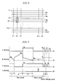
- FIG. 6 shows a PDP electrode arrangement diagram according to certain exemplary embodiments of the present invention.
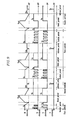
- FIG. 7 shows a PDP driving waveform diagram according to a first exemplary embodiment of the present invention
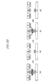
- FIGs. 8A to 8E show wall charge distribution diagrams based on the driving waveform according to the first exemplary embodiment of the present invention
- FIG. 9 shows a PDP driving waveform diagram according to a second exemplary embodiment of the present invention.
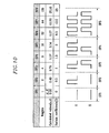
- FIG. 10 shows a calculation of the number of the sustain discharge pulses for each subfield when eight subfields are arranged and a total of fifty sustain discharge pulses for one TV field are respectively provided to the X and Y electrodes;
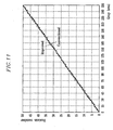
- FIG. 11 is a graph depicting the numbers of sustain discharge pulses for the respective gray scale levels according to a conventional PDP driving method and according to PDP driving methods of first and second exemplary embodiments of the present invention.
- a PDP includes address electrodes A 1 '- to A m ' arranged in parallel in the column direction, Y electrodes Y 1 ' to Y n/2+1 ' in n/2+1 rows, X electrodes X 1 ' to X n/2+1 ' in n/2+1 rows, and middle electrodes (referred to as M electrodes hereinafter) in n rows. That is, the M electrodes are arranged in the middle of the Y and X electrodes.
- the Y electrode, the X electrode, the M electrode, and the address electrode provide a four-electrode structure to form single discharge cell 30.
- the X and Y electrodes function as electrodes for applying sustain discharge voltage waveforms
- the M electrodes function as electrodes for applying a reset waveform and a scan pulse voltage.
- FIG. 7 shows a PDP driving waveform diagram according to a first exemplary embodiment of the present invention
- FIGs. 8A to 8E show distribution diagrams of wall charges based on the driving waveform shown in FIG. 7.
- a driving method according to the first exemplary embodiment will now be described with reference to FIGs. 7, and 8A to 8E.
- Each subfield includes a reset period, an address period, and a sustain period (or a sustain discharge period) according to the driving method shown in FIG. 7.
- the reset period includes an erase period (I), an M electrode rising waveform period (II), and an M electrode falling waveform period (III).
- the wall charges formed during a previous sustain discharge period are erased.
- a sustain discharge voltage pulse e.g., having a voltage of Vs
- a voltage e.g., a ground voltage
- (+) wall charges are formed on the Y electrode and the address electrode and (-) wall charges are formed on the X electrode and the M electrode, as shown in FIG. 8A.
- a waveform (a ramp waveform or a logarithmic waveform) which gently falls to the ground voltage from the voltage of Vs is applied to the M electrode while the Y electrode is biased with the voltage of Ve and the X electrode and the address electrode are biased with the ground.
- the wall charges formed during the sustain discharge period are erased as shown in FIG. 8A.
- a waveform (a ramp waveform or a logarithmic waveform) which gently rises to the voltage of Vset from the voltage of Vs is applied to the M electrode while the X and Y electrodes are biased with the ground voltage.
- a weak reset discharge is generated from the M electrode to the address electrode, the X electrode, and the Y electrode.
- the (-) wall charges are accumulated on the M electrode, and the (+) wall charges are accumulated on the address electrode, the X electrode, and the Y electrode as shown in FIG. 8B.
- a waveform (a ramp waveform or a logarithmic waveform) which gently falls to the ground voltage from the voltage of Vs is applied to the M electrode while the X and Y electrodes are biased with the voltage of Ve.
- a weak reset discharge is generated at all the discharge cells while the ramp voltage falls.
- the M electrode falling waveform period is a period for slowly reducing the wall charges accumulated during the M electrode rising waveform period, new wall charges can be set up for the next address period (or address discharge) as the time of the falling waveform is increased (i.e., as the gradient becomes gentle) since the reduced amount of wall charges can be precisely controlled.
- the previous wall charges accumulated on the respective electrode of all the cells are equivalently erased, the new (+) wall charges are stored on the address electrode, and the new (-) wall charges are concurrently stored on the X electrode, the Y electrode, and the M electrode, as shown in FIG. 8C.
- the ground voltage is sequentially applied to the M electrodes to thus apply a scan pulse, and an address voltage is applied to the address electrodes corresponding to the cells to be discharged (i.e., turned-on cells).
- the X electrode is maintained at the ground voltage, and the voltage of Ve is applied to the Y electrode (i.e., the voltage which is higher than the voltage at the X electrode is applied to the Y electrode.)
- a discharge is generated between the M electrode and the address electrode, a discharge is generated between the X electrode and the Y electrode, and as shown in FIG. 8D, the (+) charges are stored at the X and M electrodes and the (-) wall charges are stored at the Y electrode and the address electrode.
- a sustain discharge voltage pulse (having voltage Vs) is alternately applied to the X and Y electrodes (in a pulse train fashion) while the M electrode is biased with the sustain discharge voltage of Vs.
- a sustain discharge is generated at the discharge cells selected in the address period through the application of the sustain discharge voltage and the sustain discharge voltage pulse.
- discharges are generated through different discharge mechanisms in the initial sustain discharge stage and the normal stage.
- the discharge which occurs at the initial part of the sustain discharge period will be referred to as a short-gap discharge period
- the discharge at the time away from the initial part (or at normal time) will be referred to as a long-gap discharge period.
- (+) voltage pulses are applied to the X electrode and (-) voltage pulses are applied to the Y electrode (wherein the signs of (+) and (-) represent relative concepts caused by comparing the magnitude of the voltage applied to the X with the magnitude of the voltage applied to the Y electrode, and applying the (+) pulse voltages to the X electrode represents applying a voltage which is greater than the voltage applied to the Y electrode to the X electrode and the sign of (-) does not necessarily have to be a negative voltage, i.e., a voltage below 0V) in the start period of the sustain discharge.
- the (+) voltage pulses are applied to the M electrode.
- the discharges between the X electrode/M electrode and the Y electrode are generated, differing from the conventional discharge generated between the X and Y electrodes.
- the electrical field applied between the M and Y electrodes becomes greater since the distance between the M and Y electrodes is shorter than the distance between the X and Y electrodes. Therefore, the discharge between the M and Y electrodes performs a more dominant role than the discharge between the X and Y electrodes. Accordingly, the discharge which occurs at the initial part of the sustain discharge is called the short-gap discharge since the discharge between the M and Y electrodes with a relatively shorter distance performs the leading role in the earlier part of the sustain discharge.
- the discharge between the M and X electrodes or the discharge between the M and Y electrodes i.e., the short gap discharge
- the discharge between the X and Y electrodes becomes the main discharge, and as a result, the input video is displayed according to the number of discharge pulses alternately applied to the X and Y electrodes.
- the (-) wall charges are consecutively stored on the M electrode, and the (-) and (+) wall charges are alternately stored on the X and Y electrodes during the sustain discharge period in the normal state.
- a sufficient discharge is performed when less priming particles are provided since the discharge is performed by the short gap discharge between the X and M electrodes (or between the Y and M electrodes) in the initial part of the sustain discharge (e.g., during the application of the initial or first discharge pulse) , and a stable discharge is performed in the normal state since the discharge is performed according to the long gap discharge between the X and Y electrodes.
- a PDP of the present invention is driven when the waveforms of the X and Y electrodes are exchanged (or mirrored), and also when the waveforms of the X and Y electrodes are exchanged (or mirrored) in the address period.
- the reset waveform and the scan pulse waveform are mainly applied to the M electrode, and the sustain voltage waveform is mainly applied to the X and Y electrodes.
- the reset waveform applied to the M electrode can be the reset waveform shown in FIG. 7, as well as other suitable reset waveforms.
- the M electrode formed between the X and Y electrodes controls the erase period, the reset period, and the address period (during which the scan pulse waveform is applied), and the X and Y electrodes control the sustain period.
- the processes during the erase period of the reset period are normally performed irrespective of the fact that the final sustain discharge pulse of the sustain period (or a sustain discharge period) is applied to the X or Y electrode.
- the bias voltage applied to one of the X and Y electrodes during the erase period can be varied depending on the case of whether the final sustain discharge pulse of the sustain period is applied to the X electrode or the Y electrode.
- a first (or initial) sustain discharge pulse can be applied to either the X or Y electrode during the sustain period, and the voltages applied to the X and Y electrodes can be exchanged with each other.
- the bias voltage applied to the X and Y electrodes during the address period should also be varied. That is, in order to apply the first sustain discharge pulse to the X electrode, the Y electrode should be biased with the voltage of Ve, and in order to apply the first sustain discharge pulse to the Y electrode, the X electrode should be biased with the voltage of Ve.
- a method for applying the first sustain discharge pulse voltage to the X or Y electrode and applying the final sustain discharge pulse voltage to the same, based on using the X or Y electrode to control the sustain period and the M electrode to control the erase period, will now be described in detail.
- FIG. 9 shows a PDP driving waveform diagram according to a second exemplary embodiment of the present invention
- the driving waveform according to the second embodiment of FIG. 9 has substantially the same driving waveform of FIG. 7.
- the bias voltage of Ve applied to the X or Y electrode during the address period is modified in order to apply the first sustain discharge pulse to either the X or Y electrode
- the bias voltage of Vs applied to one of the X and Y electrode is modified depending on whether the final sustain discharge pulse is applied to the X electrode or the Y electrode.
- the first sustain discharge pulse is applied to the X electrode and the final sustain discharge pulse is applied to the X electrode during the sustain period of the first subfield.
- the erase operation is performed when a constant voltage of Vs (which is variable) is applied to the Y electrode during the erase period in the reset period of the second subfield since the final sustain discharge pulse has been applied to the X electrode.
- the first sustain discharge pulse is applied to the Y electrode
- the final sustain discharge pulse is applied to the Y electrode during the sustain period of the second subfield.
- the appropriate erase operation is performed when a constant voltage of Vs (which is variable) is applied to the X electrode during the erase period in the reset period of the third subfield since the final sustain discharge pulse has been applied to the Y electrode.
- the first sustain discharge pulse is applied to the X electrode
- the final sustain discharge pulse is applied to the Y electrode during the sustain period of the third subfield.
- Vs which is variable
- the PDP driving method according to the second exemplary embodiment has a feature that the first sustain discharge pulse can be randomly applied to the X or Y electrode and the final sustain discharge pulse can be randomly applied to the X or Y electrode. That is, the driving methods according to the second embodiment (or the first exemplary embodiment) do not have to be bound by the condition in which the first sustain discharge pulse has to be applied to the Y electrode and the final sustain discharge pulse has to be applied to the same in the sustain period in a like manner of the prior art.
- the number of sustain discharge pulses applied to the X electrode is different from the number of sustain discharge pulses applied to the Y electrode in the first and second subfields because of high selectivity of the electrode to which the sustain discharge pulses are applied, and the number of sustain discharge pulses (e.g., five) applied to the X electrode in the third subfield corresponds to the number of sustain discharge pulses (e.g., five) applied to the Y electrode.
- the final sustain discharge pulse in the sustain period can be applied to either the X or Y electrodes (and the first sustain discharge pulse can also be applied to either the X or Y electrodes), and hence, when a predetermined subfield A is represented with nine sustain discharge pulses, it is possible to represent the brightness which is lower by one degree than the brightness of the subfield A by using the brightness of the light waveform caused by eight sustain discharge pulses (rather than seven discharge pulses), since the representation of the brightness degree can now be allowed with just one sustain discharge pulse rather than the two sustain discharge pulses according to the conventional PDP driving method. As a result, the increased width of the minimum brightness for each degree is reduced through the PDP driving method according to the first and second embodiments, and accordingly, more advantageous gray scale linearity is obtained.
- FIG. 10 shows the calculation of the number of the sustain discharge pulses for each subfield when eight subfields are arranged, and the total of fifty sustain discharge pulses for one TV field are respectively provided to the X and Y electrodes in the PDP driving methods according to the first and second embodiments.
- FIG. 10 shows calculation of the numbers of sustain discharge pulses allocated to the respective subfields when the screen load ratio of the PDP is greater than a predetermined load ratio (representing the case in which the number of sustain discharge pulses of the subfield with the lowest weight is 0 or 1).
- a calculated value ( ⁇ . ⁇ ) of the number of the sustain discharge pulses of the respective subfields can be calculated by using the total number of sustain discharge pulses (i.e., fifty or 50) times the weight divided by 255 (where 0 represents the first of the 256 gray scales). That is, the calculated value ( ⁇ . ⁇ ) of the subfield SF2 with the weight of 2 becomes 0.4 (0.392... precisely) from the calculation of 50 (the total number of sustain discharge pulses) x 2/255.
- the calculated value ( ⁇ . ⁇ ) have a value ( ⁇ ) after (or right of) the decimal place (.) that is greater than 0.25 and less than 0.75, one sustain discharge pulse is added to represent the brightness which corresponds to 0.5. That is, one sustain discharge pulse is applied to either the X or Y electrodes.
- the number of sustain discharge pulses can be obtained from Equation 1. Equation 1
- the gray scale representation performance and gray scale linearity are improved when the load ratio of the PDP is high since the final sustain discharge pulse can be applicable to either the X electrode or the Y electrode in the PDP driving methods according to the first and second embodiments.
- FIG. 11 shows the numbers of sustain discharge pulses for the respective gray scale levels according to the conventional PDP driving method and according to the first and second exemplary embodiments of the present invention.
- the linearity of the number of the sustain discharge pulses for the respective gray scale levels according to the first and second embodiments is improved over the conventional PDP driving method.
- FIG. 11 shows the case in which fifty sustain discharge pulses are provided, and 256 gray scales and eight subfields are used, which improves the gray scale linearity and gray scale representation performance since the final sustain discharge pulse can be applied to the X or Y electrode during the sustain period when the load ratio exceeds or does not match a predetermined load ratio.
- the bad discharges are prevented by forming a middle electrode between X and Y electrodes, applying a reset waveform and a scan waveform to the middle electrode, and applying a sustain discharge voltage waveform to the X and Y electrodes.
- a gray scale linearity and gray scale representation performance are improved since the first and final sustain discharge pulses can be applied to either the X electrode or the Y electrode in the sustain period by applying the reset waveform and the scan pulse waveform to the middle electrode.
Landscapes
- Engineering & Computer Science (AREA)
- Physics & Mathematics (AREA)
- Computer Hardware Design (AREA)
- General Physics & Mathematics (AREA)
- Theoretical Computer Science (AREA)
- Power Engineering (AREA)
- Plasma & Fusion (AREA)
- Control Of Indicators Other Than Cathode Ray Tubes (AREA)
- Control Of Gas Discharge Display Tubes (AREA)
- Transforming Electric Information Into Light Information (AREA)
Applications Claiming Priority (2)
| Application Number | Priority Date | Filing Date | Title |
|---|---|---|---|
| KR1020030086097A KR100551618B1 (ko) | 2003-11-29 | 2003-11-29 | 플라즈마 디스플레이 패널의 구동 방법 |
| KR2003086097 | 2003-11-29 |
Publications (2)
| Publication Number | Publication Date |
|---|---|
| EP1538589A2 true EP1538589A2 (de) | 2005-06-08 |
| EP1538589A3 EP1538589A3 (de) | 2005-06-15 |
Family
ID=34464779
Family Applications (1)
| Application Number | Title | Priority Date | Filing Date |
|---|---|---|---|
| EP04090460A Withdrawn EP1538589A3 (de) | 2003-11-29 | 2004-11-25 | Verfahren zur Steuerung einer Plasmaanzeigevorrichtung |
Country Status (5)
| Country | Link |
|---|---|
| US (1) | US20050116898A1 (de) |
| EP (1) | EP1538589A3 (de) |
| JP (1) | JP3981113B2 (de) |
| KR (1) | KR100551618B1 (de) |
| CN (1) | CN100392704C (de) |
Cited By (1)
| Publication number | Priority date | Publication date | Assignee | Title |
|---|---|---|---|---|
| EP1845512A1 (de) * | 2006-04-13 | 2007-10-17 | Fujitsu Hitachi Plasma Display Limited | Ansteuerverfahren für eine Plasmaanzeige |
Families Citing this family (3)
| Publication number | Priority date | Publication date | Assignee | Title |
|---|---|---|---|---|
| US7719485B2 (en) * | 2005-04-21 | 2010-05-18 | Lg Electronics Inc. | Plasma display apparatus and driving method thereof |
| KR100684858B1 (ko) | 2005-11-29 | 2007-02-20 | 삼성에스디아이 주식회사 | 플라즈마 표시 장치 및 그 구동 방법 |
| KR20070111759A (ko) * | 2006-05-19 | 2007-11-22 | 엘지전자 주식회사 | 플라즈마 디스플레이 패널의 구동방법 |
Family Cites Families (10)
| Publication number | Priority date | Publication date | Assignee | Title |
|---|---|---|---|---|
| KR19980046358A (ko) * | 1996-12-12 | 1998-09-15 | 엄길용 | 플라즈마 디스플레이 패널 구조 및 그 구동방법 |
| KR100341313B1 (ko) * | 1998-11-16 | 2002-06-21 | 구자홍 | 플라즈마 디스플레이 패널과 구동장치 및 방법 |
| TW516014B (en) * | 1999-01-22 | 2003-01-01 | Matsushita Electric Industrial Co Ltd | Driving method for AC plasma display panel |
| KR100319095B1 (ko) * | 1999-03-02 | 2002-01-04 | 김순택 | 보조 전극을 갖는 플라즈마 표시 패널의 구동 방법 |
| US7227513B2 (en) * | 1999-11-15 | 2007-06-05 | Lg Electronics Inc | Plasma display and driving method thereof |
| KR20020035699A (ko) * | 2000-11-07 | 2002-05-15 | 구자홍 | 플라즈마 디스플레이 패널 및 그 구동방법 |
| KR100426186B1 (ko) * | 2000-12-28 | 2004-04-06 | 엘지전자 주식회사 | 플라즈마 디스플레이 패널 및 그 구동방법 |
| US6791516B2 (en) * | 2001-01-18 | 2004-09-14 | Lg Electronics Inc. | Method and apparatus for providing a gray level in a plasma display panel |
| FR2826166B1 (fr) * | 2001-06-13 | 2003-08-29 | Thomson Plasma | Procede de pilotage d'un panneau a plasma a decharges d'entretien co-planaires entre des electrodes en triades |
| KR100493615B1 (ko) * | 2002-04-04 | 2005-06-10 | 엘지전자 주식회사 | 플라즈마 디스플레이 패널의 구동방법 |
-
2003
- 2003-11-29 KR KR1020030086097A patent/KR100551618B1/ko not_active Expired - Fee Related
-
2004
- 2004-11-04 JP JP2004320282A patent/JP3981113B2/ja not_active Expired - Lifetime
- 2004-11-25 EP EP04090460A patent/EP1538589A3/de not_active Withdrawn
- 2004-11-29 US US10/998,687 patent/US20050116898A1/en not_active Abandoned
- 2004-11-29 CN CNB2004101037955A patent/CN100392704C/zh not_active Expired - Fee Related
Cited By (1)
| Publication number | Priority date | Publication date | Assignee | Title |
|---|---|---|---|---|
| EP1845512A1 (de) * | 2006-04-13 | 2007-10-17 | Fujitsu Hitachi Plasma Display Limited | Ansteuerverfahren für eine Plasmaanzeige |
Also Published As
| Publication number | Publication date |
|---|---|
| CN1684121A (zh) | 2005-10-19 |
| JP2005165287A (ja) | 2005-06-23 |
| EP1538589A3 (de) | 2005-06-15 |
| KR20050052233A (ko) | 2005-06-02 |
| JP3981113B2 (ja) | 2007-09-26 |
| US20050116898A1 (en) | 2005-06-02 |
| CN100392704C (zh) | 2008-06-04 |
| KR100551618B1 (ko) | 2006-02-13 |
Similar Documents
| Publication | Publication Date | Title |
|---|---|---|
| US7936320B2 (en) | Driving method of plasma display panel and display device thereof | |
| JP2005301259A (ja) | プラズマディスプレイパネルの駆動方法及びプラズマディスプレイパネル | |
| US7580010B2 (en) | Plasma display panel and driving method thereof | |
| KR19990074718A (ko) | 교류형 플라즈마 디스플레이 패널 및 구동 방법 | |
| CN102209986A (zh) | 等离子显示装置和等离子显示面板的驱动方法 | |
| US7576710B2 (en) | Plasma display panel and driving method thereof | |
| KR100667538B1 (ko) | 플라즈마 디스플레이 장치 및 그의 구동 방법 | |
| EP1538589A2 (de) | Verfahren zur Steuerung einer Plasmaanzeigevorrichtung | |
| CN100487773C (zh) | 等离子显示面板的驱动方法 | |
| KR100551124B1 (ko) | 플라즈마 디스플레이 패널의 구동 방법 | |
| US7501998B2 (en) | Plasma display device and plasma display panel driving method | |
| US7592978B2 (en) | Plasma display panel driving method | |
| US20070216603A1 (en) | Method of driving plasma display apparatus | |
| EP1835483A2 (de) | Ansteuerverfahren für eine Plasmaanzeigevorrichtung | |
| KR20080103093A (ko) | 플라즈마 디스플레이 패널의 구동 방법 및 플라즈마 디스플레이 장치 | |
| US20050116899A1 (en) | Plasma display panel driving method | |
| KR100599738B1 (ko) | 플라즈마 표시 장치 및 그 구동방법 | |
| CN101821793A (zh) | 等离子体显示装置 | |
| KR100603371B1 (ko) | 어드레스 전극라인별로 상승시간이 다른 펄스를 인가하는플라즈마 디스플레이 패널의 구동 방법 | |
| EP1672610A1 (de) | Plasmaanzeigevorrichtung und Verfahren zu ihrer Ansteuerung | |
| KR100746569B1 (ko) | 플라즈마 디스플레이 패널의 구동 방법 | |
| KR100574368B1 (ko) | 데이터 집적회로 및 이를 이용한 플라즈마 디스플레이패널의 구동장치 | |
| KR100511794B1 (ko) | 플라즈마 디스플레이 패널의 구동방법 | |
| KR20050040561A (ko) | 플라즈마 디스플레이 패널의 구동 장치 및 구동 방법 | |
| KR100599644B1 (ko) | 플라즈마 디스플레이 패널 및 그의 구동 방법 |
Legal Events
| Date | Code | Title | Description |
|---|---|---|---|
| PUAI | Public reference made under article 153(3) epc to a published international application that has entered the european phase |
Free format text: ORIGINAL CODE: 0009012 |
|
| PUAL | Search report despatched |
Free format text: ORIGINAL CODE: 0009013 |
|
| 17P | Request for examination filed |
Effective date: 20041202 |
|
| AK | Designated contracting states |
Kind code of ref document: A2 Designated state(s): AT BE BG CH CY CZ DE DK EE ES FI FR GB GR HU IE IS IT LI LU MC NL PL PT RO SE SI SK TR |
|
| AX | Request for extension of the european patent |
Extension state: AL HR LT LV MK YU |
|
| AK | Designated contracting states |
Kind code of ref document: A3 Designated state(s): AT BE BG CH CY CZ DE DK EE ES FI FR GB GR HU IE IS IT LI LU MC NL PL PT RO SE SI SK TR |
|
| AX | Request for extension of the european patent |
Extension state: AL HR LT LV MK YU |
|
| AKX | Designation fees paid |
Designated state(s): AT BE BG CH CY CZ DE DK EE ES FI FR GB GR HU IE IS IT LI LU MC NL PL PT RO SE SI SK TR |
|
| 17Q | First examination report despatched |
Effective date: 20071102 |
|
| STAA | Information on the status of an ep patent application or granted ep patent |
Free format text: STATUS: THE APPLICATION IS DEEMED TO BE WITHDRAWN |
|
| 18D | Application deemed to be withdrawn |
Effective date: 20100601 |