EP1538708B1 - Dispositif de connection avec adaptateur - Google Patents
Dispositif de connection avec adaptateur Download PDFInfo
- Publication number
- EP1538708B1 EP1538708B1 EP20040028628 EP04028628A EP1538708B1 EP 1538708 B1 EP1538708 B1 EP 1538708B1 EP 20040028628 EP20040028628 EP 20040028628 EP 04028628 A EP04028628 A EP 04028628A EP 1538708 B1 EP1538708 B1 EP 1538708B1
- Authority
- EP
- European Patent Office
- Prior art keywords
- plug
- fluid
- type
- branch channels
- connector set
- Prior art date
- Legal status (The legal status is an assumption and is not a legal conclusion. Google has not performed a legal analysis and makes no representation as to the accuracy of the status listed.)
- Expired - Lifetime
Links
- 239000012530 fluid Substances 0.000 claims description 122
- 238000001746 injection moulding Methods 0.000 claims description 3
- 238000007789 sealing Methods 0.000 claims description 3
- 238000005516 engineering process Methods 0.000 claims description 2
- 230000008878 coupling Effects 0.000 description 3
- 238000010168 coupling process Methods 0.000 description 3
- 238000005859 coupling reaction Methods 0.000 description 3
- 238000004519 manufacturing process Methods 0.000 description 2
- 230000000712 assembly Effects 0.000 description 1
- 238000000429 assembly Methods 0.000 description 1
- 230000005540 biological transmission Effects 0.000 description 1
- 238000002347 injection Methods 0.000 description 1
- 239000007924 injection Substances 0.000 description 1
- 238000009434 installation Methods 0.000 description 1
- 239000000463 material Substances 0.000 description 1
- 230000013011 mating Effects 0.000 description 1
- 238000000034 method Methods 0.000 description 1
- 238000000926 separation method Methods 0.000 description 1
- 230000007704 transition Effects 0.000 description 1
Images


Classifications
-
- F—MECHANICAL ENGINEERING; LIGHTING; HEATING; WEAPONS; BLASTING
- F16—ENGINEERING ELEMENTS AND UNITS; GENERAL MEASURES FOR PRODUCING AND MAINTAINING EFFECTIVE FUNCTIONING OF MACHINES OR INSTALLATIONS; THERMAL INSULATION IN GENERAL
- F16L—PIPES; JOINTS OR FITTINGS FOR PIPES; SUPPORTS FOR PIPES, CABLES OR PROTECTIVE TUBING; MEANS FOR THERMAL INSULATION IN GENERAL
- F16L47/00—Connecting arrangements or other fittings specially adapted to be made of plastics or to be used with pipes made of plastics
- F16L47/26—Connecting arrangements or other fittings specially adapted to be made of plastics or to be used with pipes made of plastics for branching pipes; for joining pipes to walls; Adaptors therefor
- F16L47/32—Branch units, e.g. made in one piece, welded, riveted
-
- F—MECHANICAL ENGINEERING; LIGHTING; HEATING; WEAPONS; BLASTING
- F16—ENGINEERING ELEMENTS AND UNITS; GENERAL MEASURES FOR PRODUCING AND MAINTAINING EFFECTIVE FUNCTIONING OF MACHINES OR INSTALLATIONS; THERMAL INSULATION IN GENERAL
- F16L—PIPES; JOINTS OR FITTINGS FOR PIPES; SUPPORTS FOR PIPES, CABLES OR PROTECTIVE TUBING; MEANS FOR THERMAL INSULATION IN GENERAL
- F16L37/00—Couplings of the quick-acting type
- F16L37/56—Couplings of the quick-acting type for double-walled or multi-channel pipes or pipe assemblies
-
- F—MECHANICAL ENGINEERING; LIGHTING; HEATING; WEAPONS; BLASTING
- F16—ENGINEERING ELEMENTS AND UNITS; GENERAL MEASURES FOR PRODUCING AND MAINTAINING EFFECTIVE FUNCTIONING OF MACHINES OR INSTALLATIONS; THERMAL INSULATION IN GENERAL
- F16L—PIPES; JOINTS OR FITTINGS FOR PIPES; SUPPORTS FOR PIPES, CABLES OR PROTECTIVE TUBING; MEANS FOR THERMAL INSULATION IN GENERAL
- F16L39/00—Joints or fittings for double-walled or multi-channel pipes or pipe assemblies
-
- F—MECHANICAL ENGINEERING; LIGHTING; HEATING; WEAPONS; BLASTING
- F16—ENGINEERING ELEMENTS AND UNITS; GENERAL MEASURES FOR PRODUCING AND MAINTAINING EFFECTIVE FUNCTIONING OF MACHINES OR INSTALLATIONS; THERMAL INSULATION IN GENERAL
- F16L—PIPES; JOINTS OR FITTINGS FOR PIPES; SUPPORTS FOR PIPES, CABLES OR PROTECTIVE TUBING; MEANS FOR THERMAL INSULATION IN GENERAL
- F16L41/00—Branching pipes; Joining pipes to walls
- F16L41/02—Branch units, e.g. made in one piece, welded, riveted
- F16L41/021—T- or cross-pieces
-
- F—MECHANICAL ENGINEERING; LIGHTING; HEATING; WEAPONS; BLASTING
- F16—ENGINEERING ELEMENTS AND UNITS; GENERAL MEASURES FOR PRODUCING AND MAINTAINING EFFECTIVE FUNCTIONING OF MACHINES OR INSTALLATIONS; THERMAL INSULATION IN GENERAL
- F16L—PIPES; JOINTS OR FITTINGS FOR PIPES; SUPPORTS FOR PIPES, CABLES OR PROTECTIVE TUBING; MEANS FOR THERMAL INSULATION IN GENERAL
- F16L41/00—Branching pipes; Joining pipes to walls
- F16L41/02—Branch units, e.g. made in one piece, welded, riveted
- F16L41/023—Y- pieces
-
- H—ELECTRICITY
- H01—ELECTRIC ELEMENTS
- H01R—ELECTRICALLY-CONDUCTIVE CONNECTIONS; STRUCTURAL ASSOCIATIONS OF A PLURALITY OF MUTUALLY-INSULATED ELECTRICAL CONNECTING ELEMENTS; COUPLING DEVICES; CURRENT COLLECTORS
- H01R13/00—Details of coupling devices of the kinds covered by groups H01R12/70 or H01R24/00 - H01R33/00
- H01R13/005—Electrical coupling combined with fluidic coupling
Definitions
- the invention relates to a charging connector set with a housing having a plug and a socket housing having box for transmitting electrical currents and fluids such as for a forklift, wherein mutually matched to each other on the plug, facing the socket and the socket, the plug, depending a plug-in adapter or a receiving adapter in the longitudinal direction of the plug and socket is inserted and detachably provided, wherein in the adapter in each case a fluid main channel and in this branching Fluidzweigkanäle such that the located on the outside of the plug adapter ends of the fluid branch channels are designed as hollow plug-in projections, the are inserted into the fluid branch channels of the receiving adapter to produce a fluid-tight connection in the inserted state of the plug and socket and that the central axes through the outer contours of the plug projections parallel to each other.
- This charging connector set disclosed therein has a connector housing and a socket housing.
- the connector housing is inserted into the socket housing.
- the can body has an apron which houses two pin contacts.
- the plug housing has a plug-in projection.
- the plug-in projection has two mutually parallel StiftCountageausappelgeber.
- adapters are used in the longitudinal direction of the plug and socket and provided detachably.
- the two adapters are designed differently on the socket and plug.
- One of the two adapters is designed as a plug adapter.
- This plug-in adapter has two cover projections, in which two fluid branch channels run. These fluid branch channels open into a common fluid main channel of the adapter.
- the fluid main channel of the plug adapter also ends in a plug-in approach.
- This plug-in approach is hollow, so that fluids get from one end of the plug adapter to the other end of the plug adapter.
- the matching receiving adapter which is installed in the other component of the plug or socket, takes in the mated state of the plug and socket, the plug-in projections of the plug adapter in which the fluid branch passages run on. A fluid-tight connection in the form of a coupling is thus produced in the inserted state of the plug in the box.
- a generic invention achieves this by the fact that the plug adapter-side central axes of the fluid branch channels intersect with the central axis of the main fluid channel.
- the center axes of the fluid branch channels intersect at a point on the central axis of the main fluid channel. This ensures that the flowing fluids from the fluid branch channels move in the sense of a vector addition directly into the fluid main channel. Large flow resistances are avoided.
- the center axes of the fluid branch passages are offset by 45 ° to 5 ° relative to one another, since then no turbulent flows result in the fluid passages.
- a particularly optimal value for the offset of the center axes of the fluid branch channels is an angle of 15 °.
- main fluid channel has a larger diameter than one of the fluid branch channels.
- a fluid distribution in the fluid branch passages is approximately equal.
- the amounts of fluid then meeting in the fluid main channel are also approximately equal and then distribute approximately equal in the fluid main channel, with the result that the fluid flow through the fluid skin channel is particularly good.
- plug-in projections has radial retaining projections, slipping out of the plug-in projections from the fluid branch channels of the receiving adapter or of the main fluid channel from further-passing fluid channels is better prevented in this variant.
- plug-in projections preferably the two plug-in projections in which or in which the fluid branch channels terminate, have radial grooves for receiving sealing rings.
- a plug-in adapter or a receiving adapter can be realized particularly well if the adapters are constructed symmetrically to a plane through the longitudinal axis of the adapter.
- the adapter has an axially projecting fastening tab, it is particularly well in this variant, the adapter in the plug housing or in the socket housing secure.
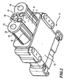
- FIG. 1 is a part of a charging connector 1, namely the can 2, shown with a socket housing 3.
- the socket housing has an apron 4, which surrounds two current-carrying contacts 5. Between the pin contacts 5, slightly offset upwards, a coding pin 6 is provided.
- the coding pin 6 has a pentagonal shape. This pentagonal shape is achieved by dividing a coding pin with a hexagonal shape in the middle.
- the pin contacts 5 do not stand over the skirt 4 addition.
- the skirt 4 surrounds the pin contacts completely along their circumference.
- a plug-in adapter 9 as in FIG. 13 is shown, plugged.
- the receiving adapter has two round main fluid channels.
- the end of the receiving adapter 8 is offset in the interior of the box 2 from the socket housing 3, in particular from the end of the skirt 4.
- the cross sections of the round fluid branch channels are the same size.
- an annular recess 10 is incorporated in each case.
- FIG. 2 is another component of a charging connector set 1, namely the plug 11 shown.
- the plug 11 has a plug housing 12, wherein a part of the plug housing 12 is formed as a plug-in projection 13.
- StiftWalletageausappelInstitut 14 are provided parallel to the longitudinal axis of the plug.
- a coding pin 15 is provided in a Codierlocha 16.
- the Codierlocha 16 next to the coding pin 15 of the plug 11 in the assembled state of can 2 and plug 11, and the coding pin 6 of the box 2 are used. If the two coding pins 6 and 16 are aligned correspondingly opposite to one another, plugging together of socket 2 and plug 11 is possible.
- FIG. 3 is the mated state of the charging connector set consisting of socket 2 and plug 11 with integrated therein adapters 7.
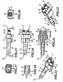
- FIG. 4 a plug-in adapter 9 is shown.
- the fluid branch channels 17 begin at one end of the receiving adapter 8. Inside the receiving adapter 8, the fluid branch channels 17 open into the main fluid channel 18. The main fluid channel 18 ends in a plug projection 19.
- an axial fastening tab 20 is formed on the underside of the receiving adapter 8. The axial fastening tab 20 comes in flush contact with the socket housing 3 or the connector housing 12th
- FIG. 5 is an adapter 7, namely the receiving adapter 8 FIG. 4 shown.
- Retaining projections 21 are provided on the outside of the plug-in projection 19.
- the retaining projections 21 are produced by externally machined grooves.
- the retaining projections 21 are conical. This is also especially good in the FIGS. 6, 7, 8 and 9 to see.
- the surface shape of the receiving adapter 8 is formed with a fastening tab 20 projecting beyond the main region of the receiving adapter.
- the plug-in projection 19 protrudes in the longitudinal direction of the adapter beyond the fastening tab 20.
- fastening tab 20 extends below the plug projection 19 in the direction of the end of the fluid main channel, away from the center of the receiving adapter 8.
- the plug-in projection 19 is spaced from the fastening tab 20.
- FIG. 8 a connection region 22 between the fluid branch channel 17 and the main fluid channel 18 is shown.
- connection region 22 connects both fluid branch channels 17 with the main fluid channel 18.
- FIG. 12 an adapter 7 is shown.
- the adapter 7 in FIG. 12 is a plug-in adapter 9.
- the plug-in adapter 9 has two fluid branch channels 17 and a main fluid channel 18.
- the fluid branch channels 17 extend in plug-in projections 19.
- the plug-in projections 19 have radial grooves 23.
- sealing rings can be used.
- the main fluid channel 18 extends into a male projection 19 having tapered retaining projections 21 below a plane through the fluid branch channels 17 and the main fluid channel 18 and parallel to the plane formed by a fastening tab 20.
- This fastening tab 20 comes into engaging contact with the socket housing 3 or the plug housing 12.
- FIG. 13 also a paragraph of the fastening tab 20 is shown.
- FIG. 14 the central axes 24 and 25 of the plug-in projections 19, in which the fluid branch passages 17 extend, are shown parallel to each other.
- the central axes 24 and 25 extend parallel to a central axis 26 of the plug-in projection 19 in which the main fluid channel 18 extends.
- the central axis 26 of the fluid main channel 18 is at the same time the center axis of the plug projection 19 of the fluid main channel 18.
- FIG. 16 shows the offset and the angle ⁇ of the central axes 27 and 28 through the fluid branch channels 17 to each other.
- the central axes 27 and 28 meet at a common point in the central axis 26.
- the fluid branch channels 17 are straight.
- the main fluid channel 18 is straight.
- a defined transition region of the fluid branch channels 17 into the main fluid channel 18 can be achieved. Particularly helpful here is the method of an injection molding process to be used.
- FIG. 15 are particularly well the grooves 23 and the retaining projections 21 shown.
- FIG. 17 the parallel fluid branch channels 17 are shown.
- the main fluid channel 18 extends, as well as in FIG. 18 is shown.
- FIG. 19 is the obliquely arranged fluid branch passage 17 with respect to the central axis 25 through the plug projection 19, in which the fluid branch passage 17 extends shown. Also, the radial groove 23, mounted radially on the outside, of the plug-in projection 19 is shown. Between the central axis 28 and the central axis 25, the angle ⁇ / 2 is formed. As a particularly advantageous for the angle ⁇ , the value of 15 ° has crystallized out.
- An adapter 7, either a receiving adapter 8 or a plug-in adapter 9 are inserted into the socket housing 3 or in the plug housing 12.
- a receiving adapter 8 and a plug-in adapter 9 in each case a part of the charging connector set 1 and that in the box 2 and the plug 11 is inserted. If plug 11 and socket 2 are plugged together, the pin contacts 5 get into the pin contact receiving recesses 14 and enable power transmission. This high currents are transmitted.
- Fluid passes in the sequence of the receiving adapter 8 through the main fluid channel 18 and the fluid branch channels 17 of the receiving adapter 8 in the fluid branch channels 17 and then into the main fluid channel 18 of the plug-in adapter 9 or vice versa.
Landscapes
- Engineering & Computer Science (AREA)
- General Engineering & Computer Science (AREA)
- Mechanical Engineering (AREA)
- Connector Housings Or Holding Contact Members (AREA)
- Quick-Acting Or Multi-Walled Pipe Joints (AREA)
Claims (12)
- Dispositif de connexion (1) pour la charge, comportant un connecteur (11) ayant un boîtier de connecteur (12) et une prise (2) ayant un boîtier de prise (3) pour le passage de courants électriques et de fluides, par exemple un chariot élévateur, selon lequel
alternativement, de façon respectivement adaptée, le connecteur (11) du côté tourné vers la prise (2) et la prise (2) du côté tourné vers le connecteur (11), comportent respectivement un adaptateur de connecteur (9) ou un adaptateur de prise (8) qui se placent dans la direction longitudinale du connecteur (11) et de la prise (2) et peuvent être détachés,
l'adaptateur (7) a un canal principal de fluide (18) et des canaux de dérivation de fluide (17) débouchant dans celui-ci de façon que les extrémités des canaux de dérivation de fluide (17) qui se trouvent sur le côté extérieur de l'adaptateur de connecteur (9) soient réalisées sous la forme de parties de connexion (19) en saillie, creuses, qui peuvent s'emmancher dans les canaux de dérivation de fluide (17) de l'adaptateur de prise (9) pour réaliser une liaison étanche au fluide lorsque le connecteur (11) et la prise (2) sont enfichés, et
les axes (24, 25) sont parallèles dans les contours extérieurs des parties de connexion (19) en saillie,
caractérisé en ce que
les canaux de dérivation de fluide (17) du côté de l'adaptateur de connecteur sont droits et leurs axes médians (27, 28) se coupent sur l'axe médian (26) du canal principal de fluide (18). - Dispositif de connexion (1) pour la charge selon la revendication 1,
caractérisé en ce que
les axes (27, 28) des canaux de dérivation de fluide (17) se coupent en un point de l'axe (26) du canal principal de fluide (18). - Dispositif de connexion (1) pour la charge selon la revendication 1 ou 2,
caractérisé en ce qu'
au moins l'un des adaptateurs (7) est réalisé par injection. - Dispositif de connexion (1) pour la charge selon les revendications 1 à 3,
caractérisé en ce que
les axes (27, 28) des canaux de dérivation de fluide (17) sont décalés l'un par rapport à l'autre d'un angle compris entre 45° et 5°. - Dispositif de connexion (1) pour la charge selon les revendications 1 à 4,
caractérisé en ce que
les axes (27, 28) des canaux de dérivation de fluide (17) sont décalés l'un par rapport à l'autre de préférence de 15°. - Dispositif de connexion (1) pour la charge selon les revendications 1 à 4,
caractérisé en ce que
le canal principal de fluide (18) se termine dans une partie de connexion (19) en saillie. - Dispositif de connexion (1) pour la charge selon les revendications 1 à 4,
caractérisé en ce que
le canal principal de fluide (18) a un diamètre plus grand que l'un des canaux de dérivation de fluide (17). - Dispositif de connexion (1) pour la charge selon les revendications 1 à 4,
caractérisé en ce que
les diamètres des canaux de dérivation de fluide (17) ont la même dimension. - Dispositif de connexion (1) pour la charge selon les revendications 1 à 4,
caractérisé en ce qu'
au moins l'une des parties de connexion (19) en saillie comporte des organes de retenue (21) en saillie, dirigés radialement. - Dispositif de connexion (1) pour la charge selon les revendications 1 à 4,
caractérisé en ce qu'
au moins l'une des parties de connexion (19) en saillie et de préférence les deux parties de connexion (19) en saillie dans laquelle ou dans lesquelles se terminent les canaux de dérivation de fluide (17) comportent des gorges radiales (23) pour recevoir des joints d'étanchéité toriques. - Dispositif de connexion (1) pour la charge selon les revendications 1 à 4,
caractérisé en ce que
l'adaptateur (7) est de construction symétrique par rapport à un plan passant par son axe longitudinal. - Dispositif de connexion (1) pour la charge selon les revendications 1 à 4,
caractérisé en ce que
l'adaptateur comporte une patte de fixation (20) venant axialement en saillie.
Applications Claiming Priority (2)
| Application Number | Priority Date | Filing Date | Title |
|---|---|---|---|
| DE20318583U DE20318583U1 (de) | 2003-12-02 | 2003-12-02 | Ladesteckverbindersatz mit Adapter |
| DE20318583U | 2003-12-02 |
Publications (3)
| Publication Number | Publication Date |
|---|---|
| EP1538708A2 EP1538708A2 (fr) | 2005-06-08 |
| EP1538708A3 EP1538708A3 (fr) | 2006-03-22 |
| EP1538708B1 true EP1538708B1 (fr) | 2009-02-18 |
Family
ID=34112197
Family Applications (1)
| Application Number | Title | Priority Date | Filing Date |
|---|---|---|---|
| EP20040028628 Expired - Lifetime EP1538708B1 (fr) | 2003-12-02 | 2004-12-02 | Dispositif de connection avec adaptateur |
Country Status (2)
| Country | Link |
|---|---|
| EP (1) | EP1538708B1 (fr) |
| DE (2) | DE20318583U1 (fr) |
Families Citing this family (13)
| Publication number | Priority date | Publication date | Assignee | Title |
|---|---|---|---|---|
| DE102005037864B4 (de) * | 2005-08-10 | 2008-11-27 | Schaltbau Gmbh | Ladesteckverbinder |
| DE102005046040A1 (de) * | 2005-09-27 | 2007-04-12 | Rema Lipprandt Gmbh & Co. Kg | Elektrische Steckverbindung und Verfahren zur Identifizierung eines Akkumulators |
| FR2903932B1 (fr) * | 2006-07-21 | 2008-10-24 | Sidel Participations | Dispositif de fabrication de recipients comprenant un moule et une fiche de raccordement fluidique. |
| FR2922053B1 (fr) * | 2007-10-08 | 2012-09-07 | Zedel | Dispositif de raccordement electrique entre un recepteur portatif et une source d'energie |
| DE102009026298A1 (de) | 2009-07-31 | 2011-02-24 | Krones Ag | Vorrichtung und Verfahren zum Blasformen von Kunststoffbehältern |
| DE102009026395A1 (de) | 2009-08-18 | 2011-02-24 | Krones Ag | Vorrichtung zum Gruppieren und/oder Vereinzeln von Artikeln |
| CA2838698A1 (fr) | 2011-06-08 | 2012-12-13 | Nxstage Medical, Inc. | Procedes, dispositifs, et systemes pour raccorder entre eux des conduits de fluides |
| EP3181978B1 (fr) | 2015-12-16 | 2020-05-06 | FASTER S.r.l. | Collecteur de couplage multiples pour raccords rapides |
| DE102016117219A1 (de) | 2016-03-10 | 2017-09-14 | Voss Automotive Gmbh | Geführte Steckverbindung |
| CN107524878B (zh) * | 2017-10-09 | 2023-09-19 | 李继前 | 具有导电功能的导管组件 |
| CN108561653A (zh) * | 2018-06-27 | 2018-09-21 | 绵阳创格科技有限公司 | 一种快速拆装的多通道装置 |
| EP3952976A4 (fr) | 2019-04-09 | 2022-12-28 | NxStage Medical, Inc. | Procédés, dispositifs et systèmes pour raccorder entre elles des conduites fluidiques |
| GB2623838B (en) * | 2022-11-25 | 2024-11-20 | Mimicrete Ltd | Cementitious product |
Family Cites Families (5)
| Publication number | Priority date | Publication date | Assignee | Title |
|---|---|---|---|---|
| DE1751053U (de) * | 1957-05-21 | 1957-08-22 | Harald Stock | Rohrverbindung aus kunststoff. |
| DE2824943C2 (de) * | 1978-06-07 | 1986-07-31 | Armaturenfabrik Hermann Voss GmbH + Co, 5272 Wipperfürth | Anschlußvorrichtung für Bremsleitungen |
| DE9016595U1 (de) * | 1990-12-06 | 1992-04-02 | Schaltbau GmbH, 8000 München | Anlage zum Laden von Batterien und gleichzeitigen Austauschen der Batterieflüssigkeit |
| DE29612378U1 (de) * | 1996-07-23 | 1996-09-19 | REMA Lipprandt GmbH & Co. KG, 53175 Bonn | Mehrpolige Geräte-Steckvorrichtung bestehend aus einem Gerätestecker und/oder einer Gerätesteckdose oder Steckverbindersatz daraus, insbesondere für Elektro-Flurförderzeuge, Batterien oder Ladegeräte dafür |
| DE29822726U1 (de) * | 1998-12-21 | 1999-04-01 | Rema Lipprandt GmbH & Co KG, 53175 Bonn | Kombinierte Lade- und Fluid-/Gas-Steckvorrichtung |
-
2003
- 2003-12-02 DE DE20318583U patent/DE20318583U1/de not_active Expired - Lifetime
-
2004
- 2004-12-02 EP EP20040028628 patent/EP1538708B1/fr not_active Expired - Lifetime
- 2004-12-02 DE DE200450009005 patent/DE502004009005D1/de not_active Expired - Lifetime
Also Published As
| Publication number | Publication date |
|---|---|
| EP1538708A2 (fr) | 2005-06-08 |
| DE20318583U1 (de) | 2005-01-27 |
| EP1538708A3 (fr) | 2006-03-22 |
| DE502004009005D1 (de) | 2009-04-02 |
Similar Documents
| Publication | Publication Date | Title |
|---|---|---|
| EP0663107B1 (fr) | Paire de connecteurs a fiches | |
| DE602004011002T2 (de) | Wasserdichter Verbinder und Zusammenbauverfahren | |
| EP3453080B1 (fr) | Connecteur surmoulé | |
| EP1538708B1 (fr) | Dispositif de connection avec adaptateur | |
| EP1977484A1 (fr) | Arrangement de connecteur coaxial | |
| EP1796225B1 (fr) | Dispositif pour un câble de connexion coulissant axialement dans un boîtier de connecteur | |
| EP2515387B1 (fr) | Prise mâle | |
| DE202016102392U1 (de) | Umspritzadapter | |
| DE3514010C1 (de) | Elektrische Steckverbindung | |
| EP1913656B1 (fr) | Connecteur de charge | |
| EP1538713B1 (fr) | Dispositif de connexion avec saillie d'arrêt et encoche | |
| EP3143320B1 (fr) | Dispositif d'accouplement, en particulier à un raccord multiple | |
| EP2054973A1 (fr) | Connecteur mâle avec verrouillage secondaire pour une connexion électrique enfichable | |
| EP1569288B1 (fr) | Fiche de connection pour recharge avec un adaptateur pour emboitement | |
| WO2000038278A1 (fr) | Dispositif de raccordement pour capteur | |
| DE29508480U1 (de) | Elektrischer Steckverbinder mit Strömungsmitteldurchführung | |
| DE102005041922B4 (de) | Elektrische Steckverbindung mit federnden Brücken | |
| EP1548895A2 (fr) | Disposition de montage de connecteur électrique | |
| EP1577969B1 (fr) | Ensemble de connection electrique pour charge ayant des canaux pour fluides sur les cotés | |
| EP0379064B1 (fr) | Connecteur à accrochage pour canalisations de fluides | |
| EP1209767B1 (fr) | Ensemble de fiche pour lampes de meubles | |
| DE102018103374B3 (de) | Rundsteckverbinder für industrielle Anwendungen | |
| EP2760085A1 (fr) | Module adaptateur enfichable et son procédé de fabrication | |
| EP1746690A2 (fr) | Connecteur pour une connexion électrique | |
| DE20318251U1 (de) | Elektrische Steckverbindung und Steckverbinder |
Legal Events
| Date | Code | Title | Description |
|---|---|---|---|
| PUAI | Public reference made under article 153(3) epc to a published international application that has entered the european phase |
Free format text: ORIGINAL CODE: 0009012 |
|
| 17P | Request for examination filed |
Effective date: 20041202 |
|
| AK | Designated contracting states |
Kind code of ref document: A2 Designated state(s): AT BE BG CH CY CZ DE DK EE ES FI FR GB GR HU IE IS IT LI LT LU MC NL PL PT RO SE SI SK TR |
|
| AX | Request for extension of the european patent |
Extension state: AL BA HR LV MK YU |
|
| PUAL | Search report despatched |
Free format text: ORIGINAL CODE: 0009013 |
|
| AK | Designated contracting states |
Kind code of ref document: A3 Designated state(s): AT BE BG CH CY CZ DE DK EE ES FI FR GB GR HU IE IS IT LI LT LU MC NL PL PT RO SE SI SK TR |
|
| AX | Request for extension of the european patent |
Extension state: AL BA HR LV MK YU |
|
| AKX | Designation fees paid |
Designated state(s): DE FR GB IT SE |
|
| GRAP | Despatch of communication of intention to grant a patent |
Free format text: ORIGINAL CODE: EPIDOSNIGR1 |
|
| GRAS | Grant fee paid |
Free format text: ORIGINAL CODE: EPIDOSNIGR3 |
|
| GRAA | (expected) grant |
Free format text: ORIGINAL CODE: 0009210 |
|
| AK | Designated contracting states |
Kind code of ref document: B1 Designated state(s): DE FR GB IT SE |
|
| REG | Reference to a national code |
Ref country code: GB Ref legal event code: FG4D Free format text: NOT ENGLISH |
|
| REF | Corresponds to: |
Ref document number: 502004009005 Country of ref document: DE Date of ref document: 20090402 Kind code of ref document: P |
|
| REG | Reference to a national code |
Ref country code: SE Ref legal event code: TRGR |
|
| PLBE | No opposition filed within time limit |
Free format text: ORIGINAL CODE: 0009261 |
|
| STAA | Information on the status of an ep patent application or granted ep patent |
Free format text: STATUS: NO OPPOSITION FILED WITHIN TIME LIMIT |
|
| 26N | No opposition filed |
Effective date: 20091119 |
|
| REG | Reference to a national code |
Ref country code: FR Ref legal event code: PLFP Year of fee payment: 12 |
|
| REG | Reference to a national code |
Ref country code: FR Ref legal event code: PLFP Year of fee payment: 13 |
|
| REG | Reference to a national code |
Ref country code: FR Ref legal event code: PLFP Year of fee payment: 14 |
|
| PGFP | Annual fee paid to national office [announced via postgrant information from national office to epo] |
Ref country code: GB Payment date: 20231218 Year of fee payment: 20 |
|
| PGFP | Annual fee paid to national office [announced via postgrant information from national office to epo] |
Ref country code: SE Payment date: 20231220 Year of fee payment: 20 Ref country code: IT Payment date: 20231227 Year of fee payment: 20 Ref country code: FR Payment date: 20231220 Year of fee payment: 20 |
|
| PGFP | Annual fee paid to national office [announced via postgrant information from national office to epo] |
Ref country code: DE Payment date: 20231221 Year of fee payment: 20 |
|
| REG | Reference to a national code |
Ref country code: DE Ref legal event code: R071 Ref document number: 502004009005 Country of ref document: DE |
|
| REG | Reference to a national code |
Ref country code: GB Ref legal event code: PE20 Expiry date: 20241201 |
|
| PG25 | Lapsed in a contracting state [announced via postgrant information from national office to epo] |
Ref country code: GB Free format text: LAPSE BECAUSE OF EXPIRATION OF PROTECTION Effective date: 20241201 |
|
| REG | Reference to a national code |
Ref country code: SE Ref legal event code: EUG |
|
| PG25 | Lapsed in a contracting state [announced via postgrant information from national office to epo] |
Ref country code: GB Free format text: LAPSE BECAUSE OF EXPIRATION OF PROTECTION Effective date: 20241201 |