EP1538721A2 - Kabelübergangsstück zur elektrischen Anspeisung von Verschlussantrieben oder dergleichen - Google Patents
Kabelübergangsstück zur elektrischen Anspeisung von Verschlussantrieben oder dergleichen Download PDFInfo
- Publication number
- EP1538721A2 EP1538721A2 EP04106115A EP04106115A EP1538721A2 EP 1538721 A2 EP1538721 A2 EP 1538721A2 EP 04106115 A EP04106115 A EP 04106115A EP 04106115 A EP04106115 A EP 04106115A EP 1538721 A2 EP1538721 A2 EP 1538721A2
- Authority
- EP
- European Patent Office
- Prior art keywords
- cable
- housing
- wing
- jacket
- frame
- Prior art date
- Legal status (The legal status is an assumption and is not a legal conclusion. Google has not performed a legal analysis and makes no representation as to the accuracy of the status listed.)
- Granted
Links
Images

Classifications
-
- H—ELECTRICITY
- H02—GENERATION; CONVERSION OR DISTRIBUTION OF ELECTRIC POWER
- H02G—INSTALLATION OF ELECTRIC CABLES OR LINES, OR OF COMBINED OPTICAL AND ELECTRIC CABLES OR LINES
- H02G11/00—Arrangements of electric cables or lines between relatively-movable parts
-
- E—FIXED CONSTRUCTIONS
- E05—LOCKS; KEYS; WINDOW OR DOOR FITTINGS; SAFES
- E05B—LOCKS; ACCESSORIES THEREFOR; HANDCUFFS
- E05B47/00—Operating or controlling locks or other fastening devices by electric or magnetic means
- E05B2047/0048—Circuits, feeding, monitoring
- E05B2047/0057—Feeding
- E05B2047/0059—Feeding by transfer between frame and wing
Definitions
- the invention relates to a cable transition piece for electrical power supply of shutter drives or the like, between one to one Pivot axis pivotable wing, e.g. a door leaf, and a frame, e.g. Door frame, with one in an elastic and flexible sheath, e.g. a coil spring or a tank hose, slidably guided Cable, with the jacket on both the wing and the frame optionally releasably secured and the jacket when closed Wing in a recess, in particular in a wing or frame-side tray, lies in the rebate of the wing or frame.
- Pivot axis pivotable wing e.g. a door leaf
- a frame e.g. Door frame
- an elastic and flexible sheath e.g. a coil spring or a tank hose, slidably guided Cable
- a known embodiment uses a coil spring as a protective Coat for a freely movable cable inside.
- the coil spring ends on the one hand (wing side) at a fold and on the other hand in one (stock side) pan in the fold, so that the coil spring at closed wing is not trapped in the fold, but in the Tub lays.
- the inside of the coil spring loosely guided cable has not the elasticity of the coil spring and therefore it comes to Relative movements and stresses on the restraints the ends of the coil spring, where the cable at the fold on the Tub is attached.
- the invention aims at the cable transition piece of the above to improve the type described.
- a flat housing in particular of Plastic, provided and the coat with one end to one Housing bushing is connected to a housing narrow side and that the housing is designed to accommodate when closing the sash emerging from the jacket and through the housing passage freely in the Housing interior insertable cable or the cable loop is trained.
- the flat housing thus holds the jacket on the input side firmly, without pinching the cable there and picking up the cable inside, in particular the cable loop forming when closing the sash, while the coil spring relaxes in the tub. That's it expedient if in the interior of the housing next to one Cable exit opening a clamp attachment, e.g. a clamp, for the free end of the cable loop is provided. This clamp attachment holds the cable at the opposite of the attachment of the jacket End firmly.
- the flat Housing has a width that is slightly larger than the cable diameter, and is sunk in a recess of the wing or stick.
- a preferred embodiment is characterized in that the Housing connects directly to the tub and possibly is formed integrally with the tub.
- the tub with the housing according to the invention can be provided in the wing or in the frame be.
- a console on the housing serves to attach the jacket and the unimpeded passage of the cable into the housing interior.
- the cable attaches to its housing opposite end of a connector to the frame or wing having.
- the plug allows the disconnection of the electrical Connection in case the wing has to be unhooked.
- the housing will have a flange as well has at least one cylinder head screw for attachment and that the cylinder head screw as a clamping screw for the end of the jacket is provided.
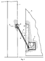
- FIG. 1 shows symbolically a part of a door frame as a frame and next to it an open one Wing, here a door leaf, in the open position in the drawing plane was rotated, leaving only a corner area, omitting a Door hinge is shown; and
- FIG. 2 shows a detailed view of that in FIG. 1 illustrated entry of a coat in the door sill.
- a wing 2 is rotatable about an axis, such as for a door leaf in a door frame is the case.
- electrical energy in the rotatable wing 2 to pass is a cable transition piece between a frame-side and the wing-side electrical wiring 3 and 4 are provided.
- the wiring 4 In the wing 2 leads the wiring 4, for example, to an electric drive (not shown) for a multi-bolt lock, so at the touch of a button, simple short key operation or code entry or recognition without effort a opening or closing can be done automatically.
- the free space between the frame 1 and the open wing 2 is by a cable 5 in an elastic flexible jacket 6, here in shape a coil spring, bridged.
- the coil spring expands when the wing 2 is opened (full lines according to drawing), and she lies down relaxed in a trough 7 in a recess in the fold of the wing 2, when the wing 2 is closed.
- the coat 6, so here the Coil spring is at one end to a plug 8 and the other Fixed at the end or next to a housing 9.
- the electric cable 5 is also fixed to the plug 8, but runs at the other end of the spring unhindered in the housing 9 a.
- Inside the housing 9 forms the Cable 5 according to Figure 1 with the wing 2 open and stretched Coil spring (sheath 6) a shortened cable loop 10 (full lines), when closing or when the door is closed and shortening Coil spring to the cable loop 11 enlarged.
- the housing 9 thus ensures the space required for unhindered and smooth (thus wear - free) pushing out of the cable 5 to Cable loop 11 when closing and retracting the cable 5 to Cable loop 10 is required when opening the wing 2.
- the housing 9 can as a separate component with a console 13 for Attachment of the jacket 6 and with a free passage for the cable 5 be formed for looping (cable loops 10 and 11).
- the Housing 9 may also form part of the tub 7 or the outer Mounting flange (forend) of the housing 9 can be used as the bottom of the trough. 7 be designed.
- the tub 7 offers a sheet metal version in Deep-drawing process (bending or stamping) and for the housing 9 a Plastic version, wherein the console 13 and the implementation of the Wiring 4 each have a housing narrow side and a housing cover a flat side are provided.
- the console 13 thus protrudes into the trough 7 and has to fixation the tub 7 in a flange 18 a bore 14.
- the Coil spring has at its end a straight spring extension 15.
- FIG. 2 is in the housing 9 further in the extension of the Console opening a bore 16 executed.
- the bore 16 opens into the channel of the bore 14 a.
- the straight spring extension 15 through the bore 16 is inserted into the bore 14 and by screwing a Cylinder head bolt 17 attached to the housing 9.
- the Pan 7 with the housing 9 by means of the cylinder head screw 17th mitverschraubt.
- the cylinder head bolt 17 thus has a Dual function.
- a similar fixation of the jacket 6 is provided on the plug 8.
- the cable is 5 only at its end beyond the loop (10 or 11) through the Clamp 12 held.
- the housing 9 with the tub 7 also be provided on the frame side.
- the plug 8 allows the unhooking of the wing 2 without intervention in the electrical system.
Landscapes
- Installation Of Indoor Wiring (AREA)
- Insulated Conductors (AREA)
- Lock And Its Accessories (AREA)
- Details Of Connecting Devices For Male And Female Coupling (AREA)
- Coupling Device And Connection With Printed Circuit (AREA)
- Communication Cables (AREA)
- Insertion, Bundling And Securing Of Wires For Electric Apparatuses (AREA)
- Electric Cable Arrangement Between Relatively Moving Parts (AREA)
Abstract
Description
Claims (7)
- Kabelübergangsstück zur elektrischen Anspeisung von Verschlussantrieben oder dergleichen, zwischen einem um eine Drehachse schwenkbaren Flügel, z.B. einem Türblatt, und einem Rahmen, z.B. Türstock, mit einem in einem elastischen und biegsamen Mantel, z.B. einer Schraubenfeder oder einem Panzerschlauch, verschiebbar geführten Kabel, wobei der Mantel sowohl am Flügel als auch am Rahmen gegebenenfalls lösbar befestigt ist und der Mantel bei geschlossenem Flügel in einer Ausnehmung, insbesondere in einer flügel- oder rahmenseitigen Wanne, im Falz des Flügels oder Rahmens liegt, dadurch gekennzeichnet, dass ein flaches Gehäuse (9), insbesondere aus Kunststoff, vorgesehen und der Mantel (6) mit einem Ende an eine Gehäusedurchführung an einer Gehäuseschmalseite angeschlossen ist und dass das Gehäuse (9) zur Aufnahme des beim Schließen des Flügels (2) aus dem Mantel (6) austretenden und durch die Gehäusedurchführung frei in den Gehäuseinnenraum einschiebbaren Kabels (5) bzw. der Kabelschlaufe (11) ausgebildet ist.
- Kabelübergangsstück nach Anspruch 1, dadurch gekennzeichnet, dass im Inneren des Gehäuses (9) nächst einer Kabelaustrittsöffnung eine Klemmbefestigung, z.B. eine Klemmschelle (12), für das freie Ende der Kabelschlaufe (10 bzw. 11) vorgesehen ist.
- Kabelübergangsstück nach Anspruch 1, dadurch gekennzeichnet, dass das Gehäuse (9) unmittelbar an die Wanne (7) anschließt und gegebenenfalls einstückig mit der Wanne (7) ausgebildet ist.
- Kabelübergangsstück nach einem der Ansprüche 1 bis 3, dadurch gekennzeichnet, dass an dem flachen Gehäuse (9) an einer Schmalseite eine Konsole (13) zur Befestigung des Mantels (6) vorgesehen ist, und dass die Konsole (13) eine Öffnung für den freien Durchgang des Kabels (5) als Kabeldurchführung mit axialer Verschiebbarkeit des Kabels (5) aufweist.
- Kabelübergangsstück nach Anspruch 4, dadurch gekennzeichnet, dass die Konsole (13) in das Innere der Wanne (7) ragt und zur Befestigung des Mantels (6) ein Gewinde an der Konsole (13) vorgesehen ist, dessen Mantelachse einen spitzen Winkel zur Längsachse der Wanne (7) einschließt.
- Kabelübergangsstück nach einem der Ansprüche 1 bis 5, dadurch gekennzeichnet, dass das Kabel (5) an seinem dem Gehäuse (9) gegenüberliegenden Ende eine Steckverbindung (Stecker 8) zum Rahmen (1) bzw. Flügel (2) aufweist.
- Kabelübergangsstück nach einem der Ansprüche 1 bis 6, dadurch gekennzeichnet, dass das Gehäuse (9) einen Flansch (18) sowie mindestens eine Zylinderkopfschraube (17) zur Befestigung aufweist und dass die Zylinderkopfschraube (17) als Klemmschraube für das Ende des Mantels (9) vorgesehen ist.
Priority Applications (1)
| Application Number | Priority Date | Filing Date | Title |
|---|---|---|---|
| PL04106115T PL1538721T3 (pl) | 2003-12-05 | 2004-11-26 | Element przejściowy kabla do elektrycznie zasilanych napędów zamka lub tym podobnych |
Applications Claiming Priority (2)
| Application Number | Priority Date | Filing Date | Title |
|---|---|---|---|
| AT19592003 | 2003-12-05 | ||
| AT0195903A AT414003B (de) | 2003-12-05 | 2003-12-05 | Kabelübergangsstück zur elektrischen anspeisung von verschlussantrieben oder dergleichen |
Publications (3)
| Publication Number | Publication Date |
|---|---|
| EP1538721A2 true EP1538721A2 (de) | 2005-06-08 |
| EP1538721A3 EP1538721A3 (de) | 2006-06-07 |
| EP1538721B1 EP1538721B1 (de) | 2007-05-02 |
Family
ID=34437854
Family Applications (1)
| Application Number | Title | Priority Date | Filing Date |
|---|---|---|---|
| EP04106115A Expired - Lifetime EP1538721B1 (de) | 2003-12-05 | 2004-11-26 | Kabelübergangsstück zur elektrischen Anspeisung von Verschlussantrieben oder dergleichen |
Country Status (4)
| Country | Link |
|---|---|
| EP (1) | EP1538721B1 (de) |
| AT (2) | AT414003B (de) |
| DE (1) | DE502004003670D1 (de) |
| PL (1) | PL1538721T3 (de) |
Cited By (1)
| Publication number | Priority date | Publication date | Assignee | Title |
|---|---|---|---|---|
| EP2632006A3 (de) * | 2012-02-27 | 2014-04-02 | ASSA ABLOY Sicherheitstechnik GmbH | Kabelübergang zwischen zwei relativ zueinander beweglichen Elementen, insbesondere zwischen einem Türflügel und einem Türrahmen sowie Panikbalken oder Panikstange mit einem solchen Kabelübergang |
Family Cites Families (8)
| Publication number | Priority date | Publication date | Assignee | Title |
|---|---|---|---|---|
| FI60057C (fi) * | 1980-02-20 | 1981-11-10 | Waertsilae Oy Ab | Anordning vid doerr |
| JPH0610545A (ja) * | 1992-06-25 | 1994-01-18 | Matsushita Electric Works Ltd | 扉用電気錠装置 |
| JPH0678430A (ja) * | 1992-08-26 | 1994-03-18 | Matsushita Electric Works Ltd | 可撓電線保護具 |
| JP4070043B2 (ja) * | 1998-01-08 | 2008-04-02 | 美和ロック株式会社 | 扉用電気錠の結線を含む取付け方法 |
| DE10053153C1 (de) * | 2000-10-26 | 2002-06-27 | Elektro Special Bedarf Link Gm | Trennbarer Kabelübergang |
| JP4439720B2 (ja) * | 2000-12-07 | 2010-03-24 | 株式会社ゴール | 電波式キーシステム |
| DE10126785C5 (de) * | 2001-06-01 | 2013-02-07 | Aug. Winkhaus Gmbh & Co. Kg | Kabelübergang |
| DE10234413C1 (de) * | 2002-07-29 | 2003-12-04 | Elektro Special Bedarf Link Gm | Flexibler Kabelübergang |
-
2003
- 2003-12-05 AT AT0195903A patent/AT414003B/de not_active IP Right Cessation
-
2004
- 2004-11-26 DE DE502004003670T patent/DE502004003670D1/de not_active Expired - Lifetime
- 2004-11-26 PL PL04106115T patent/PL1538721T3/pl unknown
- 2004-11-26 AT AT04106115T patent/ATE361570T1/de active
- 2004-11-26 EP EP04106115A patent/EP1538721B1/de not_active Expired - Lifetime
Cited By (1)
| Publication number | Priority date | Publication date | Assignee | Title |
|---|---|---|---|---|
| EP2632006A3 (de) * | 2012-02-27 | 2014-04-02 | ASSA ABLOY Sicherheitstechnik GmbH | Kabelübergang zwischen zwei relativ zueinander beweglichen Elementen, insbesondere zwischen einem Türflügel und einem Türrahmen sowie Panikbalken oder Panikstange mit einem solchen Kabelübergang |
Also Published As
| Publication number | Publication date |
|---|---|
| PL1538721T3 (pl) | 2007-10-31 |
| EP1538721A3 (de) | 2006-06-07 |
| DE502004003670D1 (de) | 2007-06-14 |
| EP1538721B1 (de) | 2007-05-02 |
| ATE361570T1 (de) | 2007-05-15 |
| AT414003B (de) | 2006-08-15 |
| ATA19592003A (de) | 2005-11-15 |
Similar Documents
| Publication | Publication Date | Title |
|---|---|---|
| EP2159360B1 (de) | Fenster oder Tür mit einem Beschlag | |
| DE4109852A1 (de) | Vorrichtung zum auf- und zumachen, insbesondere von vorzugsweise nach aussen zu oeffnenden ausstellfenstern | |
| DE102008004429A1 (de) | Endabdeckung für ein Gehäuse mit Stelleinrichtung und Vorrichtung zur Gehäuseanordnung an einem Flügel | |
| EP3759301B1 (de) | Vorrichtung zur abdeckung eines schiebeflügels oder verschiebbaren hebe-schiebeflügels eines fensters oder einer tür | |
| EP1538721B1 (de) | Kabelübergangsstück zur elektrischen Anspeisung von Verschlussantrieben oder dergleichen | |
| EP2840209A1 (de) | Scharnier sowie Türanordnung | |
| EP3333345B1 (de) | Scharnier sowie türanordnung | |
| DE102014101583A1 (de) | Türantriebsvorrichtung sowie damit versehene drehtür | |
| DE102019118535A1 (de) | Verschluss für ein fenster, eine tür oder dergleichen | |
| EP3070236B1 (de) | Notentriegelungsvorrichtung | |
| DE10039829B4 (de) | Vorsatztür mit Schließmechanismus | |
| EP3450662B1 (de) | Antriebseinrichtung eines treibstangenbeschlages und verfahren zur montage einer solchen antreibseinrichtung | |
| DE29506799U1 (de) | Vorrichtung an einem Türschloß | |
| DE69901359T2 (de) | Zwischengeschaltete Sicherheitsvorrichtung für Drehtür oder Drehfenster | |
| DE19902888C2 (de) | Baukasten-System für ein Verschwindscharnier | |
| EP3530852B1 (de) | Fenster oder tür mit einem beschlag | |
| EP4446533B1 (de) | Fenster oder fenstertür mit einem auf einem hauptflügel aufgesetzten vorsatzflügel | |
| EP2105565B1 (de) | Antrieb für einen flügel eines fensters | |
| DE2717419A1 (de) | Verriegelungsvorrichtung fuer schiebefenster und schiebetueren | |
| DE29818045U1 (de) | Beschlag für Klappfenster, insbesondere von Wohnwagen, Mobilheimen u.dgl. | |
| DE7707617U1 (de) | Urch das fensterverschlussgetriebe betaetigte feststellvorrichtung fuer den fluegel von fenstern, tueren oder dergleichen in einer spaltoffenen lueftungsstellung | |
| DE102004030877B4 (de) | Offenstellungsarretierung für Tür- und Fensterflügel | |
| DE29602615U1 (de) | Vorrichtung zur Sicherung eines zwischen zwei Endstellungen bewegbaren Bauteils zum Verschließen einer Wandöffnung eines Gebäudes | |
| EP0574594A1 (de) | Beschlagsystem | |
| DE102019007008A1 (de) | Ausstellvorrichtung für ein Dreh-Kipp-Flügel eines Fensters oder einer Tür |
Legal Events
| Date | Code | Title | Description |
|---|---|---|---|
| PUAI | Public reference made under article 153(3) epc to a published international application that has entered the european phase |
Free format text: ORIGINAL CODE: 0009012 |
|
| AK | Designated contracting states |
Kind code of ref document: A2 Designated state(s): AT BE BG CH CY CZ DE DK EE ES FI FR GB GR HU IE IS IT LI LU MC NL PL PT RO SE SI SK TR |
|
| AX | Request for extension of the european patent |
Extension state: AL HR LT LV MK YU |
|
| PUAL | Search report despatched |
Free format text: ORIGINAL CODE: 0009013 |
|
| AK | Designated contracting states |
Kind code of ref document: A3 Designated state(s): AT BE BG CH CY CZ DE DK EE ES FI FR GB GR HU IE IS IT LI LU MC NL PL PT RO SE SI SK TR |
|
| AX | Request for extension of the european patent |
Extension state: AL HR LT LV MK YU |
|
| 17P | Request for examination filed |
Effective date: 20060919 |
|
| GRAP | Despatch of communication of intention to grant a patent |
Free format text: ORIGINAL CODE: EPIDOSNIGR1 |
|
| AKX | Designation fees paid |
Designated state(s): AT BE BG CH CY CZ DE DK EE ES FI FR GB GR HU IE IS IT LI LU MC NL PL PT RO SE SI SK TR |
|
| GRAS | Grant fee paid |
Free format text: ORIGINAL CODE: EPIDOSNIGR3 |
|
| GRAA | (expected) grant |
Free format text: ORIGINAL CODE: 0009210 |
|
| AK | Designated contracting states |
Kind code of ref document: B1 Designated state(s): AT BE BG CH CY CZ DE DK EE ES FI FR GB GR HU IE IS IT LI LU MC NL PL PT RO SE SI SK TR |
|
| PG25 | Lapsed in a contracting state [announced via postgrant information from national office to epo] |
Ref country code: FI Free format text: LAPSE BECAUSE OF FAILURE TO SUBMIT A TRANSLATION OF THE DESCRIPTION OR TO PAY THE FEE WITHIN THE PRESCRIBED TIME-LIMIT Effective date: 20070502 |
|
| REG | Reference to a national code |
Ref country code: GB Ref legal event code: FG4D Free format text: NOT ENGLISH |
|
| REG | Reference to a national code |
Ref country code: CH Ref legal event code: EP |
|
| REG | Reference to a national code |
Ref country code: IE Ref legal event code: FG4D Free format text: LANGUAGE OF EP DOCUMENT: GERMAN |
|
| REF | Corresponds to: |
Ref document number: 502004003670 Country of ref document: DE Date of ref document: 20070614 Kind code of ref document: P |
|
| REG | Reference to a national code |
Ref country code: CH Ref legal event code: NV Representative=s name: SCHNEIDER FELDMANN AG PATENT- UND MARKENANWAELTE |
|
| PG25 | Lapsed in a contracting state [announced via postgrant information from national office to epo] |
Ref country code: SE Free format text: LAPSE BECAUSE OF FAILURE TO SUBMIT A TRANSLATION OF THE DESCRIPTION OR TO PAY THE FEE WITHIN THE PRESCRIBED TIME-LIMIT Effective date: 20070802 |
|
| PG25 | Lapsed in a contracting state [announced via postgrant information from national office to epo] |
Ref country code: ES Free format text: LAPSE BECAUSE OF FAILURE TO SUBMIT A TRANSLATION OF THE DESCRIPTION OR TO PAY THE FEE WITHIN THE PRESCRIBED TIME-LIMIT Effective date: 20070813 |
|
| PG25 | Lapsed in a contracting state [announced via postgrant information from national office to epo] |
Ref country code: IS Free format text: LAPSE BECAUSE OF FAILURE TO SUBMIT A TRANSLATION OF THE DESCRIPTION OR TO PAY THE FEE WITHIN THE PRESCRIBED TIME-LIMIT Effective date: 20070902 |
|
| GBT | Gb: translation of ep patent filed (gb section 77(6)(a)/1977) |
Effective date: 20070809 |
|
| ET | Fr: translation filed | ||
| REG | Reference to a national code |
Ref country code: PL Ref legal event code: T3 |
|
| NLV1 | Nl: lapsed or annulled due to failure to fulfill the requirements of art. 29p and 29m of the patents act | ||
| REG | Reference to a national code |
Ref country code: IE Ref legal event code: FD4D |
|
| PG25 | Lapsed in a contracting state [announced via postgrant information from national office to epo] |
Ref country code: PT Free format text: LAPSE BECAUSE OF FAILURE TO SUBMIT A TRANSLATION OF THE DESCRIPTION OR TO PAY THE FEE WITHIN THE PRESCRIBED TIME-LIMIT Effective date: 20071002 Ref country code: NL Free format text: LAPSE BECAUSE OF FAILURE TO SUBMIT A TRANSLATION OF THE DESCRIPTION OR TO PAY THE FEE WITHIN THE PRESCRIBED TIME-LIMIT Effective date: 20070502 Ref country code: SI Free format text: LAPSE BECAUSE OF FAILURE TO SUBMIT A TRANSLATION OF THE DESCRIPTION OR TO PAY THE FEE WITHIN THE PRESCRIBED TIME-LIMIT Effective date: 20070502 Ref country code: BG Free format text: LAPSE BECAUSE OF FAILURE TO SUBMIT A TRANSLATION OF THE DESCRIPTION OR TO PAY THE FEE WITHIN THE PRESCRIBED TIME-LIMIT Effective date: 20070802 Ref country code: IE Free format text: LAPSE BECAUSE OF FAILURE TO SUBMIT A TRANSLATION OF THE DESCRIPTION OR TO PAY THE FEE WITHIN THE PRESCRIBED TIME-LIMIT Effective date: 20070502 Ref country code: DK Free format text: LAPSE BECAUSE OF FAILURE TO SUBMIT A TRANSLATION OF THE DESCRIPTION OR TO PAY THE FEE WITHIN THE PRESCRIBED TIME-LIMIT Effective date: 20070502 |
|
| PG25 | Lapsed in a contracting state [announced via postgrant information from national office to epo] |
Ref country code: SK Free format text: LAPSE BECAUSE OF FAILURE TO SUBMIT A TRANSLATION OF THE DESCRIPTION OR TO PAY THE FEE WITHIN THE PRESCRIBED TIME-LIMIT Effective date: 20070502 |
|
| PLBE | No opposition filed within time limit |
Free format text: ORIGINAL CODE: 0009261 |
|
| STAA | Information on the status of an ep patent application or granted ep patent |
Free format text: STATUS: NO OPPOSITION FILED WITHIN TIME LIMIT |
|
| 26N | No opposition filed |
Effective date: 20080205 |
|
| PG25 | Lapsed in a contracting state [announced via postgrant information from national office to epo] |
Ref country code: GR Free format text: LAPSE BECAUSE OF FAILURE TO SUBMIT A TRANSLATION OF THE DESCRIPTION OR TO PAY THE FEE WITHIN THE PRESCRIBED TIME-LIMIT Effective date: 20070803 |
|
| PG25 | Lapsed in a contracting state [announced via postgrant information from national office to epo] |
Ref country code: RO Free format text: LAPSE BECAUSE OF FAILURE TO SUBMIT A TRANSLATION OF THE DESCRIPTION OR TO PAY THE FEE WITHIN THE PRESCRIBED TIME-LIMIT Effective date: 20070502 |
|
| PG25 | Lapsed in a contracting state [announced via postgrant information from national office to epo] |
Ref country code: MC Free format text: LAPSE BECAUSE OF NON-PAYMENT OF DUE FEES Effective date: 20071130 |
|
| PG25 | Lapsed in a contracting state [announced via postgrant information from national office to epo] |
Ref country code: EE Free format text: LAPSE BECAUSE OF FAILURE TO SUBMIT A TRANSLATION OF THE DESCRIPTION OR TO PAY THE FEE WITHIN THE PRESCRIBED TIME-LIMIT Effective date: 20070502 |
|
| PG25 | Lapsed in a contracting state [announced via postgrant information from national office to epo] |
Ref country code: CY Free format text: LAPSE BECAUSE OF FAILURE TO SUBMIT A TRANSLATION OF THE DESCRIPTION OR TO PAY THE FEE WITHIN THE PRESCRIBED TIME-LIMIT Effective date: 20070502 |
|
| PG25 | Lapsed in a contracting state [announced via postgrant information from national office to epo] |
Ref country code: LU Free format text: LAPSE BECAUSE OF NON-PAYMENT OF DUE FEES Effective date: 20071126 |
|
| PG25 | Lapsed in a contracting state [announced via postgrant information from national office to epo] |
Ref country code: HU Free format text: LAPSE BECAUSE OF FAILURE TO SUBMIT A TRANSLATION OF THE DESCRIPTION OR TO PAY THE FEE WITHIN THE PRESCRIBED TIME-LIMIT Effective date: 20071103 Ref country code: TR Free format text: LAPSE BECAUSE OF FAILURE TO SUBMIT A TRANSLATION OF THE DESCRIPTION OR TO PAY THE FEE WITHIN THE PRESCRIBED TIME-LIMIT Effective date: 20070502 |
|
| PGFP | Annual fee paid to national office [announced via postgrant information from national office to epo] |
Ref country code: FR Payment date: 20131028 Year of fee payment: 10 Ref country code: AT Payment date: 20131129 Year of fee payment: 10 Ref country code: GB Payment date: 20131108 Year of fee payment: 10 Ref country code: CZ Payment date: 20131101 Year of fee payment: 10 |
|
| PGFP | Annual fee paid to national office [announced via postgrant information from national office to epo] |
Ref country code: IT Payment date: 20131126 Year of fee payment: 10 Ref country code: PL Payment date: 20131105 Year of fee payment: 10 Ref country code: BE Payment date: 20131112 Year of fee payment: 10 |
|
| PGFP | Annual fee paid to national office [announced via postgrant information from national office to epo] |
Ref country code: CH Payment date: 20140224 Year of fee payment: 10 |
|
| PG25 | Lapsed in a contracting state [announced via postgrant information from national office to epo] |
Ref country code: BE Free format text: LAPSE BECAUSE OF NON-PAYMENT OF DUE FEES Effective date: 20141130 |
|
| REG | Reference to a national code |
Ref country code: CH Ref legal event code: PL |
|
| REG | Reference to a national code |
Ref country code: AT Ref legal event code: MM01 Ref document number: 361570 Country of ref document: AT Kind code of ref document: T Effective date: 20141126 |
|
| GBPC | Gb: european patent ceased through non-payment of renewal fee |
Effective date: 20141126 |
|
| PG25 | Lapsed in a contracting state [announced via postgrant information from national office to epo] |
Ref country code: LI Free format text: LAPSE BECAUSE OF NON-PAYMENT OF DUE FEES Effective date: 20141130 Ref country code: CH Free format text: LAPSE BECAUSE OF NON-PAYMENT OF DUE FEES Effective date: 20141130 Ref country code: CZ Free format text: LAPSE BECAUSE OF NON-PAYMENT OF DUE FEES Effective date: 20141126 |
|
| REG | Reference to a national code |
Ref country code: FR Ref legal event code: ST Effective date: 20150731 |
|
| PG25 | Lapsed in a contracting state [announced via postgrant information from national office to epo] |
Ref country code: AT Free format text: LAPSE BECAUSE OF NON-PAYMENT OF DUE FEES Effective date: 20141126 |
|
| REG | Reference to a national code |
Ref country code: DE Ref legal event code: R084 Ref document number: 502004003670 Country of ref document: DE |
|
| REG | Reference to a national code |
Ref country code: DE Ref legal event code: R082 Ref document number: 502004003670 Country of ref document: DE Representative=s name: JECK - FLECK - HERRMANN PATENTANWAELTE, DE Ref country code: DE Ref legal event code: R081 Ref document number: 502004003670 Country of ref document: DE Owner name: ROTO FRANK AKTIENGESELLSCHAFT, DE Free format text: FORMER OWNER: ROTO FRANK AG, 70771 LEINFELDEN-ECHTERDINGEN, DE Ref country code: DE Ref legal event code: R082 Ref document number: 502004003670 Country of ref document: DE Representative=s name: JECK - FLECK PATENTANWAELTE, DE |
|
| PG25 | Lapsed in a contracting state [announced via postgrant information from national office to epo] |
Ref country code: GB Free format text: LAPSE BECAUSE OF NON-PAYMENT OF DUE FEES Effective date: 20141126 |
|
| PG25 | Lapsed in a contracting state [announced via postgrant information from national office to epo] |
Ref country code: FR Free format text: LAPSE BECAUSE OF NON-PAYMENT OF DUE FEES Effective date: 20141201 |
|
| PG25 | Lapsed in a contracting state [announced via postgrant information from national office to epo] |
Ref country code: IT Free format text: LAPSE BECAUSE OF NON-PAYMENT OF DUE FEES Effective date: 20141126 |
|
| PG25 | Lapsed in a contracting state [announced via postgrant information from national office to epo] |
Ref country code: PL Free format text: LAPSE BECAUSE OF NON-PAYMENT OF DUE FEES Effective date: 20141126 |
|
| PGFP | Annual fee paid to national office [announced via postgrant information from national office to epo] |
Ref country code: DE Payment date: 20181031 Year of fee payment: 15 |
|
| REG | Reference to a national code |
Ref country code: DE Ref legal event code: R119 Ref document number: 502004003670 Country of ref document: DE |
|
| PG25 | Lapsed in a contracting state [announced via postgrant information from national office to epo] |
Ref country code: DE Free format text: LAPSE BECAUSE OF NON-PAYMENT OF DUE FEES Effective date: 20200603 |