EP1538773A2 - Codes non systématiques de répétition et accumulation pour le codage et le décodage de l'information dans un système de communication - Google Patents
Codes non systématiques de répétition et accumulation pour le codage et le décodage de l'information dans un système de communication Download PDFInfo
- Publication number
- EP1538773A2 EP1538773A2 EP04256848A EP04256848A EP1538773A2 EP 1538773 A2 EP1538773 A2 EP 1538773A2 EP 04256848 A EP04256848 A EP 04256848A EP 04256848 A EP04256848 A EP 04256848A EP 1538773 A2 EP1538773 A2 EP 1538773A2
- Authority
- EP
- European Patent Office
- Prior art keywords
- bits
- decoding
- output
- codes
- nonsystematic
- Prior art date
- Legal status (The legal status is an assumption and is not a legal conclusion. Google has not performed a legal analysis and makes no representation as to the accuracy of the status listed.)
- Withdrawn
Links
Images


Classifications
-
- H—ELECTRICITY
- H03—ELECTRONIC CIRCUITRY
- H03M—CODING; DECODING; CODE CONVERSION IN GENERAL
- H03M13/00—Coding, decoding or code conversion, for error detection or error correction; Coding theory basic assumptions; Coding bounds; Error probability evaluation methods; Channel models; Simulation or testing of codes
- H03M13/03—Error detection or forward error correction by redundancy in data representation, i.e. code words containing more digits than the source words
- H03M13/05—Error detection or forward error correction by redundancy in data representation, i.e. code words containing more digits than the source words using block codes, i.e. a predetermined number of check bits joined to a predetermined number of information bits
- H03M13/11—Error detection or forward error correction by redundancy in data representation, i.e. code words containing more digits than the source words using block codes, i.e. a predetermined number of check bits joined to a predetermined number of information bits using multiple parity bits
- H03M13/1102—Codes on graphs and decoding on graphs, e.g. low-density parity check [LDPC] codes
- H03M13/1191—Codes on graphs other than LDPC codes
- H03M13/1194—Repeat-accumulate [RA] codes
-
- H—ELECTRICITY
- H04—ELECTRIC COMMUNICATION TECHNIQUE
- H04L—TRANSMISSION OF DIGITAL INFORMATION, e.g. TELEGRAPHIC COMMUNICATION
- H04L1/00—Arrangements for detecting or preventing errors in the information received
- H04L1/004—Arrangements for detecting or preventing errors in the information received by using forward error control
- H04L1/0045—Arrangements at the receiver end
- H04L1/0047—Decoding adapted to other signal detection operation
- H04L1/005—Iterative decoding, including iteration between signal detection and decoding operation
-
- H—ELECTRICITY
- H04—ELECTRIC COMMUNICATION TECHNIQUE
- H04B—TRANSMISSION
- H04B7/00—Radio transmission systems, i.e. using radiation field
- H04B7/02—Diversity systems; Multi-antenna system, i.e. transmission or reception using multiple antennas
- H04B7/04—Diversity systems; Multi-antenna system, i.e. transmission or reception using multiple antennas using two or more spaced independent antennas
- H04B7/0413—MIMO systems
-
- H—ELECTRICITY
- H04—ELECTRIC COMMUNICATION TECHNIQUE
- H04L—TRANSMISSION OF DIGITAL INFORMATION, e.g. TELEGRAPHIC COMMUNICATION
- H04L1/00—Arrangements for detecting or preventing errors in the information received
- H04L1/004—Arrangements for detecting or preventing errors in the information received by using forward error control
- H04L1/0041—Arrangements at the transmitter end
-
- H—ELECTRICITY
- H04—ELECTRIC COMMUNICATION TECHNIQUE
- H04L—TRANSMISSION OF DIGITAL INFORMATION, e.g. TELEGRAPHIC COMMUNICATION
- H04L1/00—Arrangements for detecting or preventing errors in the information received
- H04L1/004—Arrangements for detecting or preventing errors in the information received by using forward error control
- H04L1/0056—Systems characterized by the type of code used
- H04L1/0057—Block codes
-
- H—ELECTRICITY
- H04—ELECTRIC COMMUNICATION TECHNIQUE
- H04L—TRANSMISSION OF DIGITAL INFORMATION, e.g. TELEGRAPHIC COMMUNICATION
- H04L1/00—Arrangements for detecting or preventing errors in the information received
- H04L1/004—Arrangements for detecting or preventing errors in the information received by using forward error control
- H04L1/0056—Systems characterized by the type of code used
- H04L1/0064—Concatenated codes
- H04L1/0065—Serial concatenated codes
-
- H—ELECTRICITY
- H04—ELECTRIC COMMUNICATION TECHNIQUE
- H04L—TRANSMISSION OF DIGITAL INFORMATION, e.g. TELEGRAPHIC COMMUNICATION
- H04L1/00—Arrangements for detecting or preventing errors in the information received
- H04L1/004—Arrangements for detecting or preventing errors in the information received by using forward error control
- H04L1/0056—Systems characterized by the type of code used
- H04L1/0071—Use of interleaving
-
- H—ELECTRICITY
- H04—ELECTRIC COMMUNICATION TECHNIQUE
- H04L—TRANSMISSION OF DIGITAL INFORMATION, e.g. TELEGRAPHIC COMMUNICATION
- H04L1/00—Arrangements for detecting or preventing errors in the information received
- H04L1/02—Arrangements for detecting or preventing errors in the information received by diversity reception
- H04L1/06—Arrangements for detecting or preventing errors in the information received by diversity reception using space diversity
-
- H—ELECTRICITY
- H04—ELECTRIC COMMUNICATION TECHNIQUE
- H04L—TRANSMISSION OF DIGITAL INFORMATION, e.g. TELEGRAPHIC COMMUNICATION
- H04L1/00—Arrangements for detecting or preventing errors in the information received
- H04L1/08—Arrangements for detecting or preventing errors in the information received by repeating transmission, e.g. Verdan system
Definitions
- the present invention relates to the use of nonsystematic repeat-accumulate codes in a communication system.
- MIMO multi-input multi-output
- a data stream to be transmitted is processed, using well-known techniques, to form space-time coded signals that are transmitted over a plurality of different transmit antennas.
- the signals emanating from the transmit antennas arrive at receive antennas as a superposition of each of the transmitted signals. Though the transmitted signals interfere with each other, received signals are processed in the receiver to separate out and decode these super-positioned signals.
- the receiver typically uses a MIMO detector and channel decoder several times over in an effort to reduce the number of bit errors in the decoded signal.
- the channel coding used to code signals of the data stream to form the space-time coded signals is used at the receiver for error correction. That is, the channel decoder at the receiver may be able to recover bits that arrive at the receiver in error, due to noise and/or interference.
- a strong channel code such as a turbo code, has been used.
- an increase in the strength of the channel code does not necessarily result in a reduction in the errors in the decoded signal at the receiver when the number of antennas at the transmitter is larger than the number of antennas at the receiver.
- LDPC low density parity check codes
- the transfer characteristic curve may be defined as a curve that shows extrinsic mutual information content of soft value bits (bits whose value conveys both whether the bit is a one or zero and an indication of the certainty with which this is known) at an output of a device (such as a channel decoder) determined as a function of the mutual information content of soft value bits at the input of the device.
- a transfer characteristic curve may be illustrated with extrinsic information transfer (EXIT) charts, bit error rate (BER) charts or signal to noise ratio (SNR) charts, as is known in the art.
- RA codes have recently been devised as a competitive alternative to parallel concatenated (PC or turbo) and LDPC codes.
- RA codes are encoded by using four types of operations, in the following order: variable rate repetition encoders, an interleaver, variable rate modulo-2 adders (single parity check encoders), and an accumulator.
- the general structure is described in a paper by H. Jin, et al., entitled “Irregular repeat-accumulate codes," in Proc. 2 nd Int. Symp. On Turbo Codes, Brest, France, 2000.
- MIMO multi-input, multi-output
- both LDPC and RA codes can operate near capacity of the system.
- One type of irregular RA codes are known as nonsystematic repeat-accumulate (RA) codes.
- Nonsystematic RA codes are a developing family of iteratively decodable channel codes that can operate close to capacity for many channels.
- An exemplary embodiment of the present invention is directed to a method of transmitting data in a communication system.
- bits of a data stream are encoded with nonsystematic repeat-accumulate codes and mapped to a signal for transmission.
- Another exemplary embodiment is directed to a method of decoding data in a communication system.
- One or more transmitted signals of a data stream encoded with nonsystematic repeat-accumulate codes is detected so as to obtain a detection output.
- the detection output is decoded so as to obtain a decoded stream of bits for reconstructing the data stream.
- Another exemplary embodiment is directed to a combined detector/decoder arrangement for a receiver in a communication system.
- the arrangement may include a detector for performing a bit detection from channel information received on one or more channels to provide a detector output.
- a first node decoder may determine extrinsic values from the detector output for use as a priori knowledge by the detector for a next bit detection iteration.
- the first node decoder also outputs reliability values based on the detector output that are input to a second node decoder.
- the second node decoder determines modified reliability values from the received reliability values.
- a combined output from the detector and first node decoder is represented by a first transfer characteristic curve.
- An output from the second node decoder is represented by a second transfer characteristic curve adapted so as to substantially match the first transfer characteristic curve, so as to facilitate decoding the received channel information at a highest possible data rate with a reduced bit error rate.
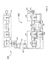
- FIG. 1 illustrates an encoder arrangement for a transmitter and a combined detector/decoder arrangement for a receiver of a MIMO communication system in accordance with an exemplary embodiment of the invention.
- FIG. 2 illustrates an encoder arrangement for a transmitter and a combined detector/decoder arrangement for a receiver of a MIMO communication system in accordance with another exemplary embodiment of the invention.
- FIGS. 3A-3C illustrates trellis configurations and edge labeling in accordance with the exemplary embodiments of the present invention.
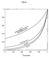
- FIG. 4 is a graph illustrating EXIT curves for an ACC and a bi-regular CND in accordance with an exemplary embodiment of the invention.
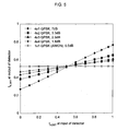
- FIG. 5 is a graph illustrating MIMO detector EXIT curves in accordance with the exemplary embodiments of the invention.
- FIG. 6 illustrates EXIT curves for a combined MIMO detector, accumulator decoder and check node decoder when the inner detection loop of FIG. 1 is used.
- FIG. 7 illustrates EXIT curves for the combined MIMO detector, accumulator decoder and check node decoder for trellis detection as shown in FIG. 2.
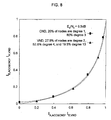
- FIG. 8 illustrates an example of an EXIT curve matching for nonsystematic check-biregular RA codes.
- FIG. 8 illustrates another example of an EXIT curve matching for nonsystematic check-biregular RA codes.
- FIG. 10 is a bit error rate (BER) chart for various MIMO channels.
- the exemplary embodiments of the present invention are directed to a modulation and coding scheme that employs nonsystematic repeat-accumulate codes (also referred to as check-biregular, nonsystematic RA (BNRA) codes) that are generated by an encoder at a transmitter and decoded by a composite detector/decoder arrangement at a receiver.
- nonsystematic repeat-accumulate codes also referred to as check-biregular, nonsystematic RA (BNRA) codes
- BNRA check-biregular, nonsystematic RA
- the composite detector/decoder arrangement employs an inner detection loop for detection and decoding of a BNRA-encoded signal.
- the composite detector/decoder arrangement employs a trellis detector, or 'MIMO trellis detection' for detection and decoding of the BNRA-encoded signal.
- close-to-capacity performance may be achieved by substantially matching transfer characteristics curves ('curve-fitting') of a decoder and a detector in the composite arrangement.
- a modulation and coding scheme employing BNRA codes and MIMO trellis detection may reduce complexity and improve robustness against code parameter mismatches.
- BNRA codes may be designed for both scalar channels and vector channels by using a curve--fitting procedure on extrinsic information transfer (EXIT) charts, as will be seen in further detail below.
- the vector channel (multi--input, multi--output or MIMO) code designs are evaluated for two demodulator structures, namely the aforementioned inner detection loop and trellis detector.
- the exemplary embodiments use one class of codes, namely nonsystematic repeat-accumulate codes (i.e., BNRA codes). Similar designs could also be done for other code families.
- RA codes can operate near capacity for many channels, just like LDPC, parallel concatenated (PC or turbo) codes, and serially concatenated (SC) codes.
- Two classes of irregular RA codes include systematic and nonsystematic RA codes. Both classes are 'check-regular' in the sense that an encoder at the transmitter (or a decoder at the receiver) has a layer of check nodes where each check node takes as inputs exactly d c edges from an interleaver. The function of a check node is to perform a modulo-2 addition (XOR) of the d c bits represented by the input edges.
- XOR modulo-2 addition
- a degree such as a check node degree d c
- d c may therefore be considered a parameter that refers to how many bits the check node takes as its input.
- An iterative, check-regular, nonsystematic RA decoder requires degree d c > 1 to approach capacity, yet does not even begin to converge for such cases.
- the term "converge" can be understood to mean that the iterative decoder can successively reduce the number of bit errors from iteration to iteration, ultimately until no bit errors remain.
- BNRA nonsystematic RA
- M c 2.
- the average energy per transmit symbol is limited to E s , and it is assumed that E[
- 2 ] E s /M.
- R is the code rate.
- H is assumed to be known by the receiver only, and a Rayleigh fading channel is considered so that the entries of H are independent, complex, zero-mean, Gaussian random variables with unit variance.
- H remains unchanged over long time intervals, while for an ergodic channel H changes for every symbol s.
- C defined by equation (2):
- I is the identity matrix and H t denotes the complex-conjugate transpose of H. Capacity may be achieved by using Gaussian distributed symbols s, although Gray-mapped QPSK modulation was considered for the above equation.
- FIG. 1 illustrates an encoder arrangement for a transmitter and a combined detector/decoder arrangement for a receiver of a MIMO communication system in accordance with an exemplary embodiment of the invention.
- FIG. 1 illustrates a portion of a transmitter 100 and a portion of a receiver 150 in a communication system, such as a MIMO communication system, for example.
- the transmitter 100 may be representative of a transmitter at a base station
- the receiver 150 may represent a mobile station receiver, it being understood that typically both the mobile station and base station have a transmitter and a receiver.
- data to be transmitted from a transmitter in a communication system may be divided into a plurality of data streams by well known techniques (not shown).
- a binary source may represent a source of bits for a given data stream to be transmitted.
- the bits are to be encoded with nonsystematic repeat-accumulate codes by encoder arrangement (shown as dotted-line box 110), and then the non-systematic repeat-accumulate coded bits are mapped to a signal at QAM mapper 120 as is known, and multiplexed onto a plurality of M transmit antennas130 to produce the space-time coded signals for transmission over a plurality of M transmit antennas 130.
- Each of the space-time coded signals may be transmitted over a different one of the M transmit antennas 130.
- the encoder arrangement 110 consists of four main parts: k repetition codes, an interleaver, n single parity check codes, and a differential encoder or accumulator.
- the repetition codes may be represented as variable nodes in a variable node encoder 111, and the interleaver as an edge interleaver 112.
- the single parity check codes may be represented as check nodes of a check node layer in a check node encoder 113.
- the accumulator may be represented as a chain of check nodes in a differential encoder 114.
- bits received from binary source 102 are encoded with k repetition codes of variable rates (first encoding) at variable node encoder 111 to obtain first encoded bits.
- first encoding the encoding with repetition codes forms repeat bits (i.e., 100 bits in, 200 bits out, for example).
- the first encoded bits are subject to an interleaving process at edge interleaver 112, which permutes the first encoded bits to change bit order (re-ordering).
- the re-ordered first encoded bits are encoded with parity check codes (second encoding) in a bi-regular check node layer of the check node decoder 113 to obtain second encoded bits.
- the check node layer is biregular in that the check nodes have a degree 1 or d c (e.g., each check node in check node encoder 113 takes, as inputs, either 1 edge or d c edges from edge interleaver 112). More generally, a nonzero fraction of check nodes must have degree 1.
- the second encoded bits are then accumulated in differential encoder 114 to obtain the nonsystematic repeat-accumulate coded bits.
- the nonsystematic repeat-accumulate coded bits are subject to a channel interleaving process at channel interleaver 115, prior to mapping at QAM mapper 120.
- a channel interleaving process is necessary so as to facilitate decoding of the transmitted signal when received at a receiver in the MIMO system.
- Channel interleaving of the nonsystematic repeat-accumulate coded bits helps to break local dependencies to assist in operation of an accumulator decoder at the receiver side 150.
- the QAM mapper 120 maps the nonsystematic bits onto a signal that may be multiplexed as a plurality of space-time codes signals onto the M transmit antennas 130.
- each transmitter symbol is thus an M X 1 vector s whose entries take on complex values in a constellation set.
- Receiver 150 includes a composite detector/decoder arrangement.
- AWGN additive white Gaussian noise
- the components comprising the combined detector/decoder arrangement of receiver 150 of FIG. 1 are approximately a mirror image of the components in the encoder arrangement at the transmitter.
- the received signals are detected to obtain a detection output; and the detection output is decoded to obtain a decoded stream of bits for reconstructing the data stream.
- FIG. 2 shows a combined detector decoder arrangement for receiver 150, the arrangement represented by components in dotted line boxes 151 and 152.
- a MIMO detector 157 may process the signals received over receive antennas 155, one vector symbol at a time, and may digitally demodulate the signals, i.e. maps them from symbol space to soft value bits. For each soft bit, MIMO detector 157 computes a channel reliability value (or L-value).
- the channel output is y (y can be scalar (non-MIMO detector case) or vector (MIMO detector case) .
- b 0)/ Pr ( y
- b 1)]
- the n-channel reliability values output of decoder 157 may represent one of the nonsystematic repeat-accumulate coded bits of at least one of the signals received by the receive antennas 155 of receiver 150.
- each of the detector or decoders in FIG. 1 receives two inputs (one a feedback input), and performs an APP calculation to determine L values as a single output.
- VND 170 receives a zero valued feedback, thus only one input is shown)
- the combined detector/decoder arrangement illustratively includes an inner detection loop, i.e., iterations between the MIMO detector 157 and the accumulator decoder (ACC) 158b.
- the purpose of this loop is to adequately infuse a priori knowledge needed by the MIMO detector 157 for a next detection iteration.
- the MIMO detector 157 performs a posteriori probability (APP) bit detection by considering all 2MM c possible hypotheses on s.
- the detector 157's soft bit output ((these are the n-channel reliability values , also called L-values,) are forwarded to the accumulator decoder (ACC) 158a and 158b.
- ACC 158b computes extrinsic values from the n-channel reliability values to be used as the a priori knowledge by the detector 157 for the next detection iteration. Several detection iterations between detector 157/ACC 158b may be performed before accumulator ACC 158a decodes the detector output to generate L-values to be forwarded to CND 163a.
- inner accumulator decoder (ACC) 158a takes n channel reliability values (which have been de-interleaved at de-interleaver 156) and performs an a posteriori probability (APP) bit decoding (first decoding) over a memory one trellis of the ACC 158a.
- the ACC158a receives two kinds of soft bit values (L-values): those from the MIMO signal (y), and those from the check node decoder (CND) 163b. Accordingly, an APP decoding process is done in ACC158a to compute a log-likelihood ratio (L-value) for each bit.
- the L-values output of ACC 158a represent partially decoded bits.
- the partially decoded bits are from the bits that were encoded with the repetition codes and parity check codes, which were accumulated at ACC 114 in encoder arrangement 110 to form the nonsystematic repeat-accumulate encoded bits of the received signals. In other words, one level of encoding is 'stripped away' in ACC 158a.
- the resulting output L-values are forwarded to an inner check node decoder (CND) 163a (first node decoder) that includes the n check nodes (the biregular check node layer).
- the inner CND 163a performs a second decoding on the L-values received from the ACC 158a and on feedback (the L-values received from the interleaver 167) to generate L-values that are forwarded, after de-interleaving at de-interleaver 165, to an outer variable node decoder (VND) 170 (second node decoder) comprising k variable nodes.
- VND variable node decoder
- This 'second set' of L-values generated from the second decoding may represent a plurality of partially decoded bits. These partially decoded bits are those bits that were encoded with the repetition codes, as the nonsystematic codes and parity check codes of the signal received at receiver 150 have been decoded at ACC 158a and CND 16
- the outer decoder uses these L-values to generate new L-values.
- This 'third set' of L-values may represent a plurality of completely decoded bits, as the repetition code encoding is decoded in VND 170, i.e., the bits should be reflective of the bits output from source 102 in the receiver 150.
- the third set of L-values may be forwarded to a hard decision 175 for collection, until all decoding iterations are complete.
- the L-values output of VND 170 may also be fed back through an edge interleaver 167 to an inner CND 163b.
- ACC accumulator decoder
- the output of the hard decision 175 are the receiver 150's decisions on the bits output by source 102 in the receiver 150. These decisions are delivered to a sink 180, and they should be the same as the bits from source 102 bits with a high probability.
- FIG. 2 illustrates an encoder arrangement for a transmitter and a combined detector/decoder arrangement for a receiver of a MIMO communication system in accordance with another exemplary embodiment of the invention.
- FIG. 2 is somewhat similar to FIG. 1, thus only the differences are discussed.
- the encoding arrangement 210 of transmitter 200 in FIG. 2 functions as in FIG. 1 and includes the same components, i.e., encoder arrangement 210 is the same as encoder arrangement 110 with the exception that no channel interleaver 115 is required prior to mapping the nonsystematic repeat-accumulate coded bits to QAM mapper 220. This means that in the transmitter 250, which is essentially a mirror image of receiver 200, the de-interleaver 156 is also omitted. Further, there is no inner detection loop in FIG. 2.
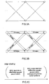
- FIGS. 3A-3C illustrates trellis configurations and edge labeling in accordance with the exemplary embodiments of the present invention.
- FIG. 3A illustrates ACC trellis sections (binary trellis) without trellis detection.
- FIG. 3B illustrates ACC trellis sections with (2 MMc -ary trellis) trellis detection.
- the trellis diagrams in FIGS. 3A and 3B show how the ACC encoding operation is being viewed at the receiver.
- the state of both trellises represents the state of the ACC.
- An edge in the trellis represents one of the possible transitions from one ACC state to another ACC state.
- Each edge is labeled with the bits put out by the ACC when the corresponding ACC state transition is made.
- each edge is labeled by one bit, meaning that each input bit is converted into one output bit.
- each edge is labeled by MM c bits, meaning that MM c input bits are viewed by the receiver as being converted into MM c output bits.
- the trellis structure is primarily useful for decoding.
- the MIMO detection and accumulator decoding is now performed in a single trellis (DET and ACC trellis) detector/decoder 257.
- This trellis has two states (0, 1) and 2 MMc incoming/outgoing edges per state, each edge being labeled by the MM c bits corresponding to one vector-channel symbol s, as shown in FIG. 3C.
- the transition from one state to the next can be determined by running MMc bits through the differential encoder, with 2 MMc-1 transitions arriving in state 0, and 2 MMc -1 transitions arriving in state 1.
- FIG. 3A illustrates a memory one binary trellis that has two states.
- the ACC 158a/158b may be embodied as this exemplary binary trellis in the inner detection loop of FIG. 1, where decoding may be performed using a simple BCJR algorithm, for example.
- the detector/decoder 257 may include the 2 MMc -ary trellis (4x4 QPSK symbol modulation) for the ACC portion thereof , for use with MIMO detection as shown in FIG. 2, where decoding may be performed using a tailored version of the BCJR algorithm, for example.
- Trellis detection as shown in FIG. 2 may have some advantages over the inner detection loop shown in FIG. 1. First, no inner iterations are required which reduces decoding complexity; observe that the MIMO detector must perform the same APP bit detection in FIGS. 1 and 2. Second, trellis detection is more robust against code parameter mismatches, as will be explained below.
- Close-to-capacity performance may be achieved by matching an 'outer' extrinsic information transfer (EXIT) characteristics curve of the VND (VND 170 or 270) to an 'inner' EXIT characteristics curve of the DET&ACC&CND (e.g., DET 157/257, ACC 158a/258a, CND 163a/263a).
- EXIT information transfer
- the outer VND curve is curve-fitted to the inner DET&ACC&CND curve. This may be done offline (in advance), so that a combined detector/decoder arrangement in accordance with the exemplary embodiments of the invention may be designed to decode received signals at a highest possible data rate with a lowest possible bit error rate (BER).
- BER bit error rate
- the transfer characteristic curve shows extrinsic mutual information content of soft value bits at an output of a device (generically represented by 'I E ') as a function of the mutual information content of soft value bits at the input of the device (generically represented by 'I A ').
- the I E and I A for each of the components in FIG. 1 and 2 is shown to assist in understanding the following equations and transfer charts described hereinafter. These are modeled parameters, as the actual outputs of the components in FIGS. 1 and 2 are the aforementioned L-values.
- the mutual information content of soft value bits is a value for expressing the information content of bits, in this case the bits produced by a transmitter's coding process.
- the mutual information content is plotted on a scale of 0 to 1.
- a mutual information content of 0 means that no information is known about the bits and an infinite number of bits is needed to convey one bit accurately.
- a mutual information content of 1 means that bits are known with 100% certainty so only 1 bit is needed to convey one bit accurately, and values in between mean that 1/mutual information content is the smallest number of bits needed to convey one bit accurately For example, 0.2 means that the bits are known with enough certainty so that at least 5 bits are needed to convey one bit accurately.
- a variable node of degree d v has d v incoming messages, and it decodes by adding L-values.
- the decoder outputs are shown in equation (4): where L j,in is the j th a priori L-value going into the variable node and L i , out is the i th extrinsic L-value coming out of the variable node.
- L j,in as the output L-value of an AWGN channel whose input was the j th interleaver bit transmitted using BPSK.
- the EXIT function of a degree-d v variable node may then be expressed by equation (5):
- a check node of degree d c has d c +1 incoming messages, d c from the edge interleaver 167/267, and one from the accumulator 158a (or from detector/decoder 257).
- the decoding of a degree d c check node is therefore the same as the decoding of a length d c +1 (or rate d c /( d c +1)) single parity check code.
- the output L-values are thus defined by equation (6), below.
- the indices i and j include the d c messages from the edge interleaver and the message from the accumulator.
- L j in equation (6), the indices i and j include the d c messages from the edge interleaver and the message from the accumulator.
- a duality property for erasure channels may be used that expresses the EXIT curve I E,SPC ( ⁇ ) of the length d c single parity check code in terms of the EXIT curve I E , REP ( ⁇ ) of the length d c repetition (repeat) code.
- the result is shown in equation (7): I E , SPC ( I A , d c ) ⁇ 1- I E,REP (1- I A , d c ).
- Equation (7) Simulations have shown equation (7) to be an accurate approximation, so the EXIT curve of the CND-to-ACC direction may be written as expression (8) below.
- each CND node computes extrinsic information using its L-value from the ACC, and ( d c -1) L-values from the edge interleaver.
- the EXIT function of the accumulator decoder (a unit memory trellis decoder) is computed by simulation and denoted by equation (10).
- Equations (8) through (10) may be combined to approximate the EXIT curve of the combined inner ACC and CND.
- Equation (11) illustrates the transfer curve I E,ACC&CND Of the inner decoder comprising the ACC and CND. Rather than measuring I E,ACC and computer I E,ACC&CND via equation (11), I E,ACC&CND can alternatively be directly measured. This approach is practical because the latter curve does not change for the curve fitting procedure described below.
- Equation (12) a c,i is the fraction of check nodes with degree d c,i .
- b c,i be the fraction of edges incident to check nodes having degree d c,i .
- the EXIT curve of a mixture of codes is an average of the component EXIT curves. Thus, we must average using the b c,i (and not the a c,i ) because it is the edges that carry the extrinsic messages.
- the EXIT curve of the ACC and biregular CND is therefore:
- FIG. 4 is a graph illustrating EXIT curves for an ACC and a biregular CND in accordance with an exemplary embodiment of the invention.
- Equation (14) a v,i is the fraction of variable nodes having degree
- b v,i the fraction of edges incident to variable nodes having degree
- the VND EXIT curve is therefore denoted by equation (15) below.
- the 8-PSK MIMO detector performs APP bit detection by considering all 8 hypotheses on the transmitted symbol s.
- the detector EXIT curve cannot be described in closed form, so we measure it by Monte-Carlo simulation.
- DET the detector
- EXIT curve the detector EXIT curve
- equation (17) the code rate (the overall rate is therefore 3R bits/use)
- FIG. 5 is a graph illustrating MIMO detector EXIT curves in accordance with the exemplary embodiments of the invention.
- the MIMO detector EXIT curve depends mainly on the number of transmit and receive antennas. For example, a 4X4-MIMO detector does not benefit much from a priori knowledge, i.e., the EXIT curve is rather flat and close to the horizontal line of a 1X1-detector, as shown in FIG. 5. In contrast, any detector with M much larger that N (e.g., a 4X1-MIMO detector) benefits substantially from a priori knowledge, resulting in an EXIT curve with a steep slope.
- FIG. 6 illustrates EXIT curves for a combined MIMO detector, accumulator decoder and check node decoder when the inner detection loop of FIG. 1 is used.
- FIG. 7 illustrates EXIT curves for the combined MIMO detector, accumulator decoder and check node decoder for trellis detection as shown in FIG. 2.
- the detector behavior affects the EXIT curve of the combined MIMO detector (DET), accumulator decoder (ACC) and check node decoder (CND), which are abbreviates as D&A&C.
- FIG. 6 shows such EXIT curves for different M and N antennas when an inner detection loop is used, as described with respect to FIG. 1. Observe that the 4X4-curve differs significantly from the 4X1 curve.
- FIG. 7 shows the corresponding EXIT curves for trellis detection. Observe that the curves are now closer to each other than for the inner detection loop.
- FIG. 8 illustrates an example of an EXIT curve matching for nonsystematic check-biregular RA codes.
- the VND curve (lower curve) is a mixture of curves of degree and
- the upper curve is the transfer characteristic of the combined ACC and CND (ACC&CND)
- the lower curve is the transfer characteristic of the VND, which has been designed to substantially match the combined ACC&CND curve.
- FIG. 8 shows a case where there is no MIMO detector employed, e.g., BPSK modulation without MIMO, (1 X 1 decoding). In other words, the iterative decoder shown in FIGS. 1 and 2 collapses to a single trellis with no detection iterations needed. However, FIG. 8 is provided to illustrate the significance of curve matching between the combined ACC&CND curve and the VND curve.
- the iterative decoding begins at the (0,0) point in FIG 8.
- the output extrinsic information of the first decoding iteration of the combined ACC&CND is given by the filled square above the (0,0) point. This information is also the input mutual information for the VND (shown as I A,VND in FIGS. 1 and 2).
- the output extrinsic information of the VND (I E,VND in FIGS. 1 and 2)is given by the point on the lower curve that lies directly to the right of the filled square.
- the decoder converges, desirably to the (1,1) point, in which case all errors have been corrected.
- the curves have a narrow space between them, known as a 'convergence tunnel, and do not cross (converge) until about the (1,1) point
- FIG. 9 illustrates another example of EXIT curve matching for nonsystematic check-biregular RA codes.
- FIG. 9 illustrates a case in which a receiver includes a combined detector/decoder arrangement having an inner detection loop as shown in FIG. 1, where the MIMO detector is a 4 x 1 QPSK MIMO detector.
- the lower curve is the transfer characteristic of the VND, which has been designed to substantially match a combined DET&ACC&CND curve ('inner D&A&C curve') between the curves up until about the (1,1) point.
- EXIT curve matching refers to (1) having an open convergence tunnel between the curves and (2) having this tunnel be narrow.
- the first of these conditions means that the two curves do not intersect, and that the iterative decoder can converge to the (1,1) corner point, to provide a low bit error probability.
- the second condition ensures that the coded system is operating near channel capacity (i.e., maximizing system throughput).
- code design reduces to matching the outer VND curve to the inner D&A&C-curve. This means that if several inner curves are similar, an outer curve designed for one of them will perform reasonably well for all of them. This suggests that code parameter mismatches (mismatches where an encoder and decoder synchronize a channel as something different than what it actually is) affects communication systems using trellis detection less than those using an inner detection loop.
- FIG. 10 is a bit error rate (BER) chart for various MIMO channels. The following experiment was performed to verify the prediction that systems using trellis detection are less affected to code mismatches. The inventors designed an RA code for an AWGN channel, but the RA code was used for all the MIMO channels Performance penalties were expected because the code was not matched to the detectors individually. FIG. 10 plots the simulation results.
- BER bit error rate
- trellis detection suffers much less from code parameter mismatches than an inner detection loop. This means trellis detection is more forgiving if a channel varies faster than the time needed to adjust the code parameters. Accordingly, trellis diction is more robust against code parameter mismatches.
Landscapes
- Engineering & Computer Science (AREA)
- Computer Networks & Wireless Communication (AREA)
- Signal Processing (AREA)
- Physics & Mathematics (AREA)
- Probability & Statistics with Applications (AREA)
- Theoretical Computer Science (AREA)
- Error Detection And Correction (AREA)
- Compression, Expansion, Code Conversion, And Decoders (AREA)
- Transmission Systems Not Characterized By The Medium Used For Transmission (AREA)
- Radio Transmission System (AREA)
- Detection And Prevention Of Errors In Transmission (AREA)
Applications Claiming Priority (2)
| Application Number | Priority Date | Filing Date | Title |
|---|---|---|---|
| US10/721,100 US7418051B2 (en) | 2003-11-26 | 2003-11-26 | Nonsystematic repeat-accumulate codes for encoding and decoding information in a communication system |
| US721100 | 2003-11-26 |
Publications (2)
| Publication Number | Publication Date |
|---|---|
| EP1538773A2 true EP1538773A2 (fr) | 2005-06-08 |
| EP1538773A3 EP1538773A3 (fr) | 2005-08-24 |
Family
ID=34465664
Family Applications (1)
| Application Number | Title | Priority Date | Filing Date |
|---|---|---|---|
| EP04256848A Withdrawn EP1538773A3 (fr) | 2003-11-26 | 2004-11-05 | Codes non systématiques de répétition et accumulation pour le codage et le décodage de l'information dans un système de communication |
Country Status (4)
| Country | Link |
|---|---|
| US (1) | US7418051B2 (fr) |
| EP (1) | EP1538773A3 (fr) |
| JP (1) | JP2005160106A (fr) |
| KR (1) | KR20050050606A (fr) |
Cited By (2)
| Publication number | Priority date | Publication date | Assignee | Title |
|---|---|---|---|---|
| CN105122654B (zh) * | 2012-12-03 | 2019-04-19 | Ln2 Db有限责任公司 | 用于将校验不规则非系统ira码编码和解码的系统和方法 |
| EP2936689B1 (fr) * | 2012-12-20 | 2020-03-25 | Myriota Pty Ltd | Système de communication numérique |
Families Citing this family (31)
| Publication number | Priority date | Publication date | Assignee | Title |
|---|---|---|---|---|
| KR101343072B1 (ko) * | 2009-10-30 | 2014-01-15 | 충남대학교산학협력단 | 통신 시스템에서 데이터 송신 장치 및 방법 |
| KR101009785B1 (ko) * | 2003-12-10 | 2011-01-19 | 삼성전자주식회사 | 불균일 반복 축적 부호 부호화/복호화 장치 및 방법 |
| US7237181B2 (en) * | 2003-12-22 | 2007-06-26 | Qualcomm Incorporated | Methods and apparatus for reducing error floors in message passing decoders |
| US7849377B2 (en) * | 2003-12-22 | 2010-12-07 | Koninklijke Philips Electronics N.V. | SISO decoder with sub-block processing and sub-block based stopping criterion |
| FR2865872B1 (fr) * | 2004-01-30 | 2006-04-28 | Wavecom | Procede de reception multi modulation s'appliquant a la demodulation de signaux issus de modulations dont les symboles sont inclus dans une constellation principale |
| US7831883B2 (en) * | 2004-04-02 | 2010-11-09 | Nortel Networks Limited | LDPC encoders, decoders, systems and methods |
| US7562280B2 (en) * | 2004-09-10 | 2009-07-14 | The Directv Group, Inc. | Code design and implementation improvements for low density parity check codes for wireless routers using 802.11N protocol |
| GB0423567D0 (en) * | 2004-10-23 | 2004-11-24 | Koninkl Philips Electronics Nv | Mimo system and method of operating a mimo system |
| US7958424B2 (en) * | 2005-06-22 | 2011-06-07 | Trident Microsystems (Far East) Ltd. | Multi-channel LDPC decoder architecture |
| CN101194428A (zh) * | 2005-06-27 | 2008-06-04 | 汤姆森许可贸易公司 | 迭代解码器中的停止准则 |
| US7770090B1 (en) | 2005-09-14 | 2010-08-03 | Trident Microsystems (Far East) Ltd. | Efficient decoders for LDPC codes |
| US20070081448A1 (en) * | 2005-10-06 | 2007-04-12 | Mansoor Ahmed | Partially coherent transmission for a multi-carrier communication system |
| KR100670947B1 (ko) | 2005-11-22 | 2007-01-17 | 학교법인 포항공과대학교 | Ra 부호화 방법 및 장치 |
| US7707479B2 (en) * | 2005-12-13 | 2010-04-27 | Samsung Electronics Co., Ltd. | Method of generating structured irregular low density parity checkcodes for wireless systems |
| JPWO2007108396A1 (ja) * | 2006-03-17 | 2009-08-06 | 三菱電機株式会社 | 通信装置、復号装置、情報伝送方法および復号方法 |
| US8060803B2 (en) * | 2006-05-16 | 2011-11-15 | Nokia Corporation | Method, apparatus and computer program product providing soft iterative recursive least squares (RLS) channel estimator |
| US7783952B2 (en) * | 2006-09-08 | 2010-08-24 | Motorola, Inc. | Method and apparatus for decoding data |
| US8024644B2 (en) * | 2006-11-14 | 2011-09-20 | Via Telecom Co., Ltd. | Communication signal decoding |
| US7876784B1 (en) * | 2007-09-27 | 2011-01-25 | Marvell International Ltd. | Methods and apparatus for providing receivers for use in superposition coded multi-user systems |
| FR2922699A1 (fr) * | 2007-10-18 | 2009-04-24 | Canon Kk | Decodage iteratif dans un reseau maille, procede et systeme correspondants |
| US8266495B2 (en) | 2008-02-20 | 2012-09-11 | Marvell World Trade Ltd. | Systems and methods for performing concatenated error correction |
| JP4939468B2 (ja) * | 2008-03-26 | 2012-05-23 | 株式会社日立国際電気 | 通信機 |
| US20100111145A1 (en) * | 2008-11-05 | 2010-05-06 | Broadcom Corporation | Baseband unit having bit repetitive encoded/decoding |
| US8407551B2 (en) * | 2008-12-15 | 2013-03-26 | Quantenna Communications, Inc. | Low complexity LDCP decoding |
| US8522119B2 (en) * | 2011-12-07 | 2013-08-27 | Xilinx, Inc. | Reduction in decoder loop iterations |
| US8897399B2 (en) | 2012-03-07 | 2014-11-25 | Samsung Electronics Co., Ltd. | Communication system with signal-to-noise ratio adjustment mechanism and method of operation thereof |
| US9286154B2 (en) * | 2013-06-07 | 2016-03-15 | Alcatel Lucent | Error correction for entangled quantum states |
| CN105634654B (zh) * | 2014-10-27 | 2019-12-17 | 中兴通讯股份有限公司 | 多用户信息传输的叠加编码、解调方法及装置 |
| US9716601B2 (en) | 2015-04-24 | 2017-07-25 | Samsung Electronics Co., Ltd | Method and apparatus for soft detection of high order QAM symbols in MIMO channels |
| WO2019047162A1 (fr) * | 2017-09-08 | 2019-03-14 | Qualcomm Incorporated | Techniques de mappage de transmissions vers différentes couches dans des communications sans fil |
| CN116800376B (zh) * | 2023-02-13 | 2025-12-09 | 杭州电子科技大学 | 基于awgn信道的规则ra码最优码率推导方法及系统 |
Family Cites Families (9)
| Publication number | Priority date | Publication date | Assignee | Title |
|---|---|---|---|---|
| US7089477B1 (en) * | 1999-08-18 | 2006-08-08 | California Institute Of Technology | Interleaved serial concatenation forming turbo-like codes |
| US6581182B1 (en) * | 2000-05-15 | 2003-06-17 | Agere Systems Inc. | Iterative decoding with post-processing of detected encoded data |
| US7116710B1 (en) * | 2000-05-18 | 2006-10-03 | California Institute Of Technology | Serial concatenation of interleaved convolutional codes forming turbo-like codes |
| US6985536B2 (en) * | 2001-01-12 | 2006-01-10 | International Business Machines Corporation | Block coding for multilevel data communication |
| US6901119B2 (en) * | 2001-02-22 | 2005-05-31 | International Business Machines Corporation | Method and apparatus for implementing soft-input/soft-output iterative detectors/decoders |
| US7236536B2 (en) * | 2001-07-26 | 2007-06-26 | Lucent Technologies Inc. | Method and apparatus for detection and decoding of signals received from a linear propagation channel |
| US7013116B2 (en) * | 2002-06-26 | 2006-03-14 | Lucent Technologies Inc. | MIMO systems having a channel decoder matched to a MIMO detector |
| US7002900B2 (en) * | 2002-10-25 | 2006-02-21 | Qualcomm Incorporated | Transmit diversity processing for a multi-antenna communication system |
| US7458003B2 (en) * | 2003-12-01 | 2008-11-25 | Qualcomm Incorporated | Low-complexity, capacity-achieving code for communication systems |
-
2003
- 2003-11-26 US US10/721,100 patent/US7418051B2/en not_active Expired - Lifetime
-
2004
- 2004-11-05 EP EP04256848A patent/EP1538773A3/fr not_active Withdrawn
- 2004-11-26 JP JP2004341371A patent/JP2005160106A/ja active Pending
- 2004-11-26 KR KR1020040097857A patent/KR20050050606A/ko not_active Withdrawn
Non-Patent Citations (2)
| Title |
|---|
| BRINK TEN S ET AL: "DESIGN OF REPEAT-ACCUMULATE CODES FOR ITERATIVE DETECTION AND DECODING" IEEE TRANSACTIONS ON SIGNAL PROCESSING, IEEE, INC. NEW YORK, US, vol. 51, no. 11, November 2003 (2003-11), pages 2764-2772, XP001200806 ISSN: 1053-587X * |
| HUI JIN; KHANDEKAR A; MCELIECE R: "Irregular repeat-accumulate codes" 2ND INTERNATIONAL SYMPOSIUM ON TURBO CODES AND RELATED TOPICS., - 7 September 2000 (2000-09-07) XP002333733 BRETAGNE, FRANCE Retrieved from the Internet: URL:http://www.systems.caltech.edu/EE/Facu lty/rjm/papers/Brest00.pdf> * |
Cited By (2)
| Publication number | Priority date | Publication date | Assignee | Title |
|---|---|---|---|---|
| CN105122654B (zh) * | 2012-12-03 | 2019-04-19 | Ln2 Db有限责任公司 | 用于将校验不规则非系统ira码编码和解码的系统和方法 |
| EP2936689B1 (fr) * | 2012-12-20 | 2020-03-25 | Myriota Pty Ltd | Système de communication numérique |
Also Published As
| Publication number | Publication date |
|---|---|
| US20050111564A1 (en) | 2005-05-26 |
| JP2005160106A (ja) | 2005-06-16 |
| US7418051B2 (en) | 2008-08-26 |
| KR20050050606A (ko) | 2005-05-31 |
| EP1538773A3 (fr) | 2005-08-24 |
Similar Documents
| Publication | Publication Date | Title |
|---|---|---|
| US7418051B2 (en) | Nonsystematic repeat-accumulate codes for encoding and decoding information in a communication system | |
| EP3577766B1 (fr) | Codage polaire irrégulier | |
| EP1334561B1 (fr) | Criteres d'arret pour un decodage iteratif | |
| EP1705799A1 (fr) | Procédé et appareil pour le traitement d'information | |
| US20050204273A1 (en) | Apparatus and method for encoding and decoding a space-time low density parity check code with full diversity gain | |
| CN102742201B (zh) | 用于具有半双工中继器的半正交帧系统的用于传送数字信号的方法、以及对应的程序产品和中继装置 | |
| Ramabadran et al. | Blind recognition of LDPC code parameters over erroneous channel conditions | |
| Novak et al. | The effect of unreliable LLR storage on the performance of MIMO-BICM | |
| Schreckenbach et al. | EXIT charts for iteratively decoded multilevel modulation | |
| KR20200132720A (ko) | 통신 또는 방송 시스템에서 데이터 복호화 방법 및 장치 | |
| Saha et al. | Bit-interleaved polar coded modulation with iterative decoding | |
| Yan et al. | Improved design of bit mapping based on EXIT-chart analysis for DVB-T2 system | |
| Morero et al. | Novel serial code concatenation strategies for error floor mitigation of low-density parity-check and turbo product codes | |
| Mughal et al. | Distributed reed-muller coded-cooperative spatial modulation | |
| KR101483228B1 (ko) | 인코딩 및 디코딩을 위한 장치 및 방법 | |
| Song et al. | A binary space-time code for MIMO systems | |
| Uhlemann | Hybrid ARQ using serially concatenated block codes for real-time communication: An iterative decoding approach | |
| Goswami et al. | Implementation of Turbo Trellis Coding Modulation Scheme for Fading Channel | |
| Herzet et al. | Code-aided maximum-likelihood ambiguity resolution through free-energy minimization | |
| Yano et al. | Arithmetic extended-mapping for BICM-ID with repetition codes | |
| Franceschini et al. | LDPC-coded modulations: performance bounds and a novel design criterion | |
| Dabwan et al. | Forward-Error Correction for High-Capacity Transmission Systems | |
| To et al. | Parameterized EXIT function for demapper and symbol mapping design | |
| Neto et al. | Analysis and Design of Modern Coding Schemes for Unequal Error Protection and Joint Source-Channel Coding | |
| Vu et al. | Error performance of coded modulation systems based on LDPC codes |
Legal Events
| Date | Code | Title | Description |
|---|---|---|---|
| PUAI | Public reference made under article 153(3) epc to a published international application that has entered the european phase |
Free format text: ORIGINAL CODE: 0009012 |
|
| 17P | Request for examination filed |
Effective date: 20041123 |
|
| AK | Designated contracting states |
Kind code of ref document: A2 Designated state(s): AT BE BG CH CY CZ DE DK EE ES FI FR GB GR HU IE IS IT LI LU MC NL PL PT RO SE SI SK TR |
|
| AX | Request for extension of the european patent |
Extension state: AL HR LT LV MK YU |
|
| PUAL | Search report despatched |
Free format text: ORIGINAL CODE: 0009013 |
|
| RIC1 | Information provided on ipc code assigned before grant |
Ipc: 7H 04B 7/08 B Ipc: 7H 04B 7/06 B Ipc: 7H 03M 13/29 B Ipc: 7H 04L 1/00 B Ipc: 7H 04L 1/18 A |
|
| AK | Designated contracting states |
Kind code of ref document: A3 Designated state(s): AT BE BG CH CY CZ DE DK EE ES FI FR GB GR HU IE IS IT LI LU MC NL PL PT RO SE SI SK TR |
|
| AX | Request for extension of the european patent |
Extension state: AL HR LT LV MK YU |
|
| AKX | Designation fees paid |
Designated state(s): DE FR GB |
|
| STAA | Information on the status of an ep patent application or granted ep patent |
Free format text: STATUS: THE APPLICATION IS DEEMED TO BE WITHDRAWN |
|
| 18D | Application deemed to be withdrawn |
Effective date: 20060318 |