EP1540145B1 - Nockenst sselarm f r einen verbrennungsmotor - Google Patents
Nockenst sselarm f r einen verbrennungsmotor Download PDFInfo
- Publication number
- EP1540145B1 EP1540145B1 EP03765564A EP03765564A EP1540145B1 EP 1540145 B1 EP1540145 B1 EP 1540145B1 EP 03765564 A EP03765564 A EP 03765564A EP 03765564 A EP03765564 A EP 03765564A EP 1540145 B1 EP1540145 B1 EP 1540145B1
- Authority
- EP
- European Patent Office
- Prior art keywords
- cam follower
- crankcase
- follower arm
- internal combustion
- combustion engine
- Prior art date
- Legal status (The legal status is an assumption and is not a legal conclusion. Google has not performed a legal analysis and makes no representation as to the accuracy of the status listed.)
- Expired - Lifetime
Links
- 238000002485 combustion reaction Methods 0.000 title claims abstract description 29
- 230000008878 coupling Effects 0.000 claims abstract description 4
- 238000010168 coupling process Methods 0.000 claims abstract description 4
- 238000005859 coupling reaction Methods 0.000 claims abstract description 4
- 230000004044 response Effects 0.000 claims description 5
- 230000003993 interaction Effects 0.000 claims description 3
- 239000002184 metal Substances 0.000 claims description 2
- 238000000034 method Methods 0.000 abstract 1
- 230000007246 mechanism Effects 0.000 description 13
- 238000004519 manufacturing process Methods 0.000 description 7
- 230000000295 complement effect Effects 0.000 description 2
- 239000011435 rock Substances 0.000 description 2
- 239000007858 starting material Substances 0.000 description 2
- 241000276498 Pollachius virens Species 0.000 description 1
- 238000010276 construction Methods 0.000 description 1
- 230000000763 evoking effect Effects 0.000 description 1
- 239000000446 fuel Substances 0.000 description 1
- 238000005461 lubrication Methods 0.000 description 1
- 239000000463 material Substances 0.000 description 1
- 230000004048 modification Effects 0.000 description 1
- 238000012986 modification Methods 0.000 description 1
- 239000012255 powdered metal Substances 0.000 description 1
- 230000000284 resting effect Effects 0.000 description 1
Images



Classifications
-
- F—MECHANICAL ENGINEERING; LIGHTING; HEATING; WEAPONS; BLASTING
- F01—MACHINES OR ENGINES IN GENERAL; ENGINE PLANTS IN GENERAL; STEAM ENGINES
- F01L—CYCLICALLY OPERATING VALVES FOR MACHINES OR ENGINES
- F01L13/00—Modifications of valve-gear to facilitate reversing, braking, starting, changing compression ratio, or other specific operations
- F01L13/0015—Modifications of valve-gear to facilitate reversing, braking, starting, changing compression ratio, or other specific operations for optimising engine performances by modifying valve lift according to various working parameters, e.g. rotational speed, load, torque
- F01L13/0021—Modifications of valve-gear to facilitate reversing, braking, starting, changing compression ratio, or other specific operations for optimising engine performances by modifying valve lift according to various working parameters, e.g. rotational speed, load, torque by modification of rocker arm ratio
-
- F—MECHANICAL ENGINEERING; LIGHTING; HEATING; WEAPONS; BLASTING
- F01—MACHINES OR ENGINES IN GENERAL; ENGINE PLANTS IN GENERAL; STEAM ENGINES
- F01L—CYCLICALLY OPERATING VALVES FOR MACHINES OR ENGINES
- F01L1/00—Valve-gear or valve arrangements, e.g. lift-valve gear
- F01L1/12—Transmitting gear between valve drive and valve
- F01L1/14—Tappets; Push rods
- F01L1/146—Push-rods
-
- F—MECHANICAL ENGINEERING; LIGHTING; HEATING; WEAPONS; BLASTING
- F01—MACHINES OR ENGINES IN GENERAL; ENGINE PLANTS IN GENERAL; STEAM ENGINES
- F01L—CYCLICALLY OPERATING VALVES FOR MACHINES OR ENGINES
- F01L1/00—Valve-gear or valve arrangements, e.g. lift-valve gear
- F01L1/12—Transmitting gear between valve drive and valve
- F01L1/18—Rocking arms or levers
-
- F—MECHANICAL ENGINEERING; LIGHTING; HEATING; WEAPONS; BLASTING
- F01—MACHINES OR ENGINES IN GENERAL; ENGINE PLANTS IN GENERAL; STEAM ENGINES
- F01L—CYCLICALLY OPERATING VALVES FOR MACHINES OR ENGINES
- F01L1/00—Valve-gear or valve arrangements, e.g. lift-valve gear
- F01L1/12—Transmitting gear between valve drive and valve
- F01L1/18—Rocking arms or levers
- F01L1/181—Centre pivot rocking arms
- F01L1/182—Centre pivot rocking arms the rocking arm being pivoted about an individual fulcrum, i.e. not about a common shaft
- F01L1/183—Centre pivot rocking arms the rocking arm being pivoted about an individual fulcrum, i.e. not about a common shaft of the boat type
-
- F—MECHANICAL ENGINEERING; LIGHTING; HEATING; WEAPONS; BLASTING
- F01—MACHINES OR ENGINES IN GENERAL; ENGINE PLANTS IN GENERAL; STEAM ENGINES
- F01L—CYCLICALLY OPERATING VALVES FOR MACHINES OR ENGINES
- F01L1/00—Valve-gear or valve arrangements, e.g. lift-valve gear
- F01L1/34—Valve-gear or valve arrangements, e.g. lift-valve gear characterised by the provision of means for changing the timing of the valves without changing the duration of opening and without affecting the magnitude of the valve lift
-
- F—MECHANICAL ENGINEERING; LIGHTING; HEATING; WEAPONS; BLASTING
- F01—MACHINES OR ENGINES IN GENERAL; ENGINE PLANTS IN GENERAL; STEAM ENGINES
- F01L—CYCLICALLY OPERATING VALVES FOR MACHINES OR ENGINES
- F01L1/00—Valve-gear or valve arrangements, e.g. lift-valve gear
- F01L1/46—Component parts, details, or accessories, not provided for in preceding subgroups
-
- F—MECHANICAL ENGINEERING; LIGHTING; HEATING; WEAPONS; BLASTING
- F02—COMBUSTION ENGINES; HOT-GAS OR COMBUSTION-PRODUCT ENGINE PLANTS
- F02B—INTERNAL-COMBUSTION PISTON ENGINES; COMBUSTION ENGINES IN GENERAL
- F02B63/00—Adaptations of engines for driving pumps, hand-held tools or electric generators; Portable combinations of engines with engine-driven devices
- F02B63/02—Adaptations of engines for driving pumps, hand-held tools or electric generators; Portable combinations of engines with engine-driven devices for hand-held tools
-
- F—MECHANICAL ENGINEERING; LIGHTING; HEATING; WEAPONS; BLASTING
- F01—MACHINES OR ENGINES IN GENERAL; ENGINE PLANTS IN GENERAL; STEAM ENGINES
- F01L—CYCLICALLY OPERATING VALVES FOR MACHINES OR ENGINES
- F01L1/00—Valve-gear or valve arrangements, e.g. lift-valve gear
- F01L1/02—Valve drive
- F01L1/026—Gear drive
Definitions
- the present invention relates to internal combustion engines.
- the present invention relates to engine valve trains that employ cam followers.
- valves that govern the providing of air and fuel to the engine cylinders and the expulsion of exhaust from the engine cylinders, among other functions.
- Such valves are often actuated by way of valve trains that interact with cams, which are driven by the crankshaft of the engine as gears on the crankshaft drive complementary gears associated with the cams.
- Tappet-followers, hydraulic lifters, or other lifter-type mechanisms that interface the cams move substantially linearly toward and away from the cams as the cams rotate.
- push rods in turn coupled these lifter-type mechanisms to rocker arms, which themselves are coupled to the valves. Consequently, the rotation of the cams is translated into linear motion by which the valves are opened and closed.
- valve timing settings that are appropriate for a given engine can vary depending upon a variety of factors including engine design characteristics and intended operational circumstances. With respect to some engines, it would be also desirable if the timing settings for the valves could be individually tailored for different engines during the manufacture of those engines. This would particularly be the case if the different engines were to be used in different operational circumstances. Further, in some engines, it would be desirable if the valve timing settings could be varied during operation of the engine, in response to changing operational circumstances.
- valve timing settings of engines could be varied in these manners
- internal combustion engines having the above-described design commonly are limited in terms of the manners in which and extent to which their valve timing settings can be varied.
- variation of the valve timing settings is typically only possible by adjusting the angular positioning of the cams with respect to the crankshaft. This typically is achieved by changing the relative orientation of the gears that are associated with the cams with respect to the complementary gears on the crankshaft.
- valve timing adjustments Besides being limited with respect to valve timing adjustments, internal combustion engines having the above-described valve trains have additional limitations.
- lifter-type mechanisms such as tappet-followers make it possible to translate rotational movement of the cams into linear motion, the use of such mechanism has certain drawbacks.
- tappet-followers or other litter-type mechanisms typically must have relatively wide faces that interface the cams, so that the lifter-type mechanisms are guaranteed to remain in contact with the nearest edges of the cams as the cams rotate.
- the faces on such lifter-type mechanisms tend to wear down over time.
- the lifter-type mechanisms are further prevented from moving, in directions other than toward and away from the cams, by being positioned within precise bores in the crankcase. Such precise bores can be expensive to manufacture.
- an internal combustion engine could be developer with an improved valve train design such that modifications to the valve timing setting could be more easily made. Further, it would be advantageous if the improves valve train design made it possible to make fine adjustments to the valve timing settings, rather than simply gross adjustments to those settings. Additionally, it would be advantageous if the improved valve train design alleviated the problems associated with maintaining the proper positioning of tappet- followers or other lifter-type mechanisms relative to the cams interfaced by those mechanisms.
- the GB 300, 004 fails to include the ability to adjust the angle at which the cam, cam follower arm, and push rod interact with one another.
- the '004 reference allows for a pivoting interaction between the cam follower arm and the push rod as the cam follower arm is displaces by the cam. This, however, is insufficient to allow for the timing adjustment contemplated by the present invention.
- a cam follower arm / pushrod contact interface that allows for greater range of adjustment in its positioning is a technical solution presented by the present invention.
- valve train for an internal combustion engine, where the valve train employs a cam follower arm with a curved flange (a "shoe") at one end.
- the convex aide of the shoe rides along the cam and the concave side of the shoe interfaces the push rod of the valve train.
- the push rod remains in contact with the shoe despite the movements of the cam follower arm in response to the rotation of the cam.
- a tappet-follower with a large face or other similar lifter-type mechanism is not required in order for the push rod to maintain contact with the cam.
- the present invention provides for an internal combustion engine comprising: a crankcase including a cylinder; a first valve; a first push rod; a first rocker arm supported by the crankcase and coupling the first valve to the first push rod; a first cam rotatably supported by the crankcase; and a first cam follower arm having first and second ends and, proximate the second end, having bottom and top surfaces, wherein the first cam follower arm is rotatably supported by the crankcase about a first pivot point proximate the first end, wherein the bottom surface proximate the second end slidingly interfaces the first cam, wherein the top surface proximate the second end slidingly interfaces the first push rod, wherein the interaction of the first cam follower arm with both the first cam and the first push rod only occurs at the end region of the first cam follower arm and not within an intermediate region between the first end and the end region of the first cam follower arm, wherein the first cam follower arm includes a shoe proximate the second end, wherein the shoe includes the
- a new single cylinder, 4-stroke, internal combustion engine 100 designed by Kohler Co. of Kohler, Wisconsin includes a crankcase 110 and a blower housing 120, inside of which are a fan 130 and a flywheel 140.
- the engine 100 further includes a starter 150, a cylinder 160, a cylinder head 170, and a rocker arm cover 180. Attached to the cylinder head 170 are an air exhaust port 190 shown in Fig. 1 and an air intake port 200 shown in Fig. 2 .
- a piston 210 moves back and forth within the cylinder 160 towards and away from the cylinder head 170.
- the movement of the piston 210 in turn causes rotation of a crankshaft 220 (see Fig. 7 ), as well as rotation of the fan 130 and the flywheel 140, which are coupled to the crankshaft.
- the rotation of the fan 130 cools the engines, and the rotation of the flywheel 140, causes a relatively constant rotational momentum to be maintained.
- the engine 100 further includes an air filter 230 coupled to the air intake port 200, which filters the air required by the engine prior to the providing of the air to the cylinder head 170.
- the air provided to the air intake port. 2.00 is communicated into the cylinder 160 by way of the cylinder head 170, and exits the engine by flowing from the cylinder through the cylinder head and then out of the air exhaust port 190.
- the inflow and outflow of air into and out of the cylinder 160 by way of the cylinder head 170 is governed by an input valve 240 and an output valve 250, respectively (see Fig. 8 ).
- the engine 100 includes an oil filter 260 through which the oil of the engine 100 is passed and filtered.
- the oil filter 260 is coupled to the crankcase 110 by way of incoming and outgoing lines 270, 280, respectively, whereby pressurized oil is provided into the oil filter and then is returned from the oil filter to the crankcase.
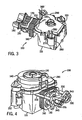
- the engine 100 is shown with the blower housing 120 removed to expose a top 290 of the crankcase 110.
- a coil 300 is shown that generates an electric current based upon rotation of the fan 130 and/or the flywheel 140, which together operate as a magneto.
- the top 290 of the crankcase 110 is shown to have a pair of.lobes 310 that cover a pair of gears 320, 325 (see Figs. 5 and 7-8 ).
- the fan 130 and the flywheel 140 are shown above the top 290 of the crankcase 110.
- FIG. 4 shows the engine 100 without the cylinder head 170 and without the rocker arm cover 180, to more clearly reveal a pair of tubes 330, 335 through which extend a pair of respective push rods 340, 345.
- the push rods 340,34.5 extend between a pair of respective rocker arms 350,355 and a pair of cams 360, 365 (see Fig. 8 ) within the crankcase 110, as discussed further below.
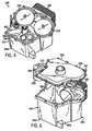
- the engine 100 is shown with the top 290 of the crankcase 110 removed from a bottom 370 of the crankcase 110 to reveal an interior 380 of the crankcase.
- the engine 100 is shown in.cut-away to exclude.portions of the engine that extend beyond the cylinder 160 such as the cylinder head 170.
- the top 290 of the crankcase 110 is shown above the bottom 370 of the crankcase in an exploded view.
- the bottom 370 includes not only a floor 390 of the crankcase, but also all six side walls 400 of the crankcase, while the top 290 only acts as the roof of the crankcase.
- the top 290 and bottom 370 are manufactured as two separate pieces such that, in order to open the crankcase 110, one physically removes the top from the bottom. Also, as shown in Fig. 5 , the pair of gears 320, 325 within the crankcase 110 are supported by and rotate upon respective shafts 410,415 (see also Fig. 8 ) which in turn are supported by the bottom 370 of the crankcase 110.
- FIG. 7 a top view of the engine 100 is provided in which additional internal components of the engine are shown.
- Fig. 7 shows the piston 210 within the cylinder 160 to be coupled to the crankshaft 220 by a connecting rod 420.
- the crankshaft 220 is in turn coupled to a rotating counterweight 430 and reciprocal weights 440, which balance the forces exerted upon the crankshaft 220 by the piston 210.
- a gear on the crankshaft 220 further is in contact with each of the gears 320,325, and thus the crankshaft communicates rotational motion to the cams 360, 365.
- the shafts 410,415 upon which the gears 320, 325 and cams 360, 365 are supported are capable of communicating oil from the floor 390 of the crankcase 110 (see Fig. 5 ) upward to the gears 320, 325.
- the incoming line 270 to the oil filter 260 is coupled to the shaft 41'0 to receive oil, while the outgoing line 280 from the oil filter is coupled to the crankshaft 220 to provide lubrication thereto.
- Fig. 7 further shows a.spark plug 450 located on the cylinder head 170, which provides sparks during power strokes of the engine to cause combustion to occur within the cylinder 160.
- the electrical energy for the spark plug 450 is provided' by the coil 300 (see Fig. 3 ).
- valve train 460 includes the gears 320,325 resting upon the shafts 410,415 and also includes the cams 360,365 underneath the gears, respectively. Additionally, respective cam follower arms 470,475 that are rotatably mounted to the crankcase 110 extend to rest upon the respective cams 360,365. The respective push rods 340,345 in turn rest upon the respective cam follower arms 470,475. As the cams 360,365 rotate, the push rods 340, 345 are temporarily forced outward away from the crankcase 110 by the cam follower arms 470,475, which slidingly interface the rotating cams.
- the engine 100 is a vertical shaft engine capable of outputting 15-20 horsepower for implementation in a variety of consumer lawn and garden machinery such as lawn mowers.
- the engine 100 can also be implemented as a horizontal shaft engine, be designed to output greater or lesser amounts of power, and/or be implemented in a variety of other types of machines, e.g., snow-blowers.
- the particular arrangement of parts within the engine 100 can vary from those shown and discussed above.
- the cams 360,365 could be located above the gears 320,325 rather than underneath the gears.
- FIG. 9 certain components of the valve train 460, particularly the cams 360,365, one of the push rods 345 and both of the cam follower arms 470,475, are shown in further detail as implemented with respect to the crankcase 110.
- Fig. 9 shows the two cam follower arms 470,475 to have respective main arm portions 580,585 that are attached to the crankcase 110 by way of respective bolts 500,505 or other fastening devices at respective pivot points 510,515 so that the cam follower arms can rotate about the pivot points.
- the respective cam follower arms 470,475 have respective shoes 520,525 that rest upon the respective cams 360,365. Bottom surfaces 530,535 of the respective shoes 520,525, which rest upon the respective cams 360,365, are convex.
- the respective push rods 340, 345 rest upon respective top surfaces 540,545 of the respective shoes 520,525.
- the top surfaces 540,545 are concave such that the push rods 340,345 remain in contact with the shoes 520,525 despite movements of the cam follower arms 470,475.
- the tips of the push rods 340.,345 also can be held in place relative to the shoes 520,525 either by way of dimples/holes in the shoes or by way of drilled guiding passage in the crankcase 110 (not shown).
- the cam follower arms 470, 475 can be made from a variety of materials, but in the present embodiment are stamped from sheet metal or made from powdered metal, to reduce manufacturing costs.
- the main arm portions 580,585 of the cam follower arms 470,475 have narrow cross sections as measured along the axes of their respective bolts 500,505 at the respective pivot points 510, 515, and the shoes 520,525 constitute flanges extending substantially perpendicularly off of the main arm portions 580,585.
- the cam follower arms 470,475 could take on any of a number of other shapes.
- the main arm portions could have a thickness that is substantially equal to the width of the shoes 520, 525.
- the pivot point 510 at which the cam follower'arm 470 is attached to the crankcase 110 by the bolt 500 (or other attachment device) can be at different locations around the cam 360.
- the other cam follower arm 475 can also be varied in its positioning with respect to its respective cam 365, by varying the pivot point 515.
- Fig. 9 in particular shows the cam follower arm 470 in first and second positions, with the first position being shown with solid lines and the second position being shown in phantom.
- the cam 360 rotates counterclockwise during operation of the engine 100.
- the second position of the cam follower arm 470 is farther counterclockwise relative to the cam 360 than the first position of the cam follower arm 470, such that the bottom surface 530 of the shoe 520 of the cam follower arm in its first position interfaces the cam 360 at a somewhat more counterclockwise location than when the cam follower arm is in its second position. Consequently, the cam follower arm 470 when in its first position provides advanced valve timing relative to when the cam follower is in its second position.
- Variation of the positioning of the cam follower arms 470,475 is not the only manner in which the timing of the valves 240,245 can be varied in relation to the crankshaft 220 and to one another.
- the valve timing can also be varied simply by varying the relative angular orientations of the cams 360, 365.
- variation of the angular orientations of the cams 360,365 is in practice limited to a discrete number of settings that correspond..to the different teeth (not shown) on the gears 320,325 that interface the crankshaft 220.
- each of the cams 360, 365 can only take on a certain number of rotational positions relative to the crankshaft and to one another, by varying which of the teeth of the gears 320,325 interface the crankshaft 220 at that particular rotational position.
- Such variation in the angular orientations of the cams 360,365 relative to the crankshaft 220 essentially allows for large changes in the timing of the cam follower arms 470,475 and corresponding large changes in the timing of the valves 240,250, both in relation to the crankshaft 220 and in relation to one another. Consequently, assuming that each tooth of the gears 320,325 occupies a certain sector on the gears and thus defines a particular angle of variation (e.g., 6 degrees), it is not necessary in practice to vary the positioning of the respective cam follower arms 470,475 in amounts greater than that particular angle, since such large variations are easily obtained simply by reorientating the gears in relation to the crankshaft.
- a particular angle of variation e.g. 6 degrees
- variation in the positioning of the respective cam follower arms 470 is typically employed to allow for "fine-tuning" of the valve timing (e.g., 2 degrees) once the positioning of the cams 360, 365 with respect to the crankshaft 220 has been set.
- the cam follower arms 470,475 are rotatably attached at the respective pivot points 510, 515 by way of the respective bolts 500, 505, which fit through corresponding holes in the crankcase 110.
- the cam follower arms 470, 475 can only be moved to different positions if other holes have been drilled (or otherwise provided) into the crankcase 110 to receive the bolts 500,505 at other locations.
- the crankcase 110 has multiple holes for receiving each of the bolts 500,505 at multiple specific locations.
- the holes for receiving the bolts 500,505 take the shape of curved slots having a width that is approximately the same as the thickness of the bolts 500, 505, but which is less than the diameter of the heads on the bolts.
- the bolts 500,505 can be positioned at any positions along the length of the slots, such that the cam follower arms 470,475 can take on any position within a range of positions.
- the positioning of the cam follower arms 470,475 is typically set during manufacture of the engine.
- the present invention is intended to encompass such alternate embodiments in which the positioning of the cam follower arms 470, 475 can be modified.after manufacture of the engine.
- such changes to the positioning of the cam follower arms 470 would have to be manually performed by a technician or other person.
- a technician could loosen the bolts 500,505, move the cam follower arms 470,475 to different positions (e-g., different positions within the curved slots discussed above), and then retighten the bolts.
- Such an adjustable positioning device could allow an operator, a mechanical component within the engine, or an engine controller to vary the positioning of the cam follower arms 470,475, and thereby adjust valve timing and engine performance.
- the adjustable positioning device would operate in response to (or include) a centrifugal governor.
- the engine 100 is shown to be a single cylinder engine having only a single intake valve 240 and a single .exhaust valve 250, and only two sets of cam follower arms 470, 475, push rods 340,345 and rocker arms 350,355. Nevertheless, in alternate embodiments, it is possible for the above-discussed cam follower arms to be implemented in engines having different configurations that can involve multiple cylinders, only one or more than two cams, and only one or more than two valves. That is, cam follower arms of the type discussed above are applicable to all types of engines that impart movement to valves by way of push rods that interface cams.
Landscapes
- Engineering & Computer Science (AREA)
- Mechanical Engineering (AREA)
- General Engineering & Computer Science (AREA)
- Chemical & Material Sciences (AREA)
- Combustion & Propulsion (AREA)
- Valve-Gear Or Valve Arrangements (AREA)
- Combustion Methods Of Internal-Combustion Engines (AREA)
Claims (13)
- Brennkraftmaschine (100), die folgendes umfasst:ein Kurbelgehäuse (110) mit einem Zylinder (160);ein erstes Ventil (240, 250);eine erste Stößelstange (340, 345);einen ersten Kipphebel (350, 355), der von dem Kurbelgehäuse (110) getragen wird und das erste Ventil (240, 250) mit der ersten Stößelstange (340, 345) koppelt;eine erste Nocke (360, 365), die drehbar von dem Kurbelgehäuse (110) getragen wird; undeinen ersten Nockenstößelarm (470, 475) mit ersten und zweiten Enden, und proximal zu dem zweiten Ende mit unteren (530, 535) und oberen (540, 545) Oberflächen;wobei der erste Nockenstößelarm (470, 475) durch das Kurbelgehäuse (110) proximal zu dem ersten Ende drehbar um einen ersten Drehpunkt (510, 515) getragen wird;wobei die untere Oberfläche (530, 535) proximal zu dem zweiten Ende gleitfähig mit der ersten Nocke (360, 365) ankoppelt;wobei die obere Oberfläche (540, 545) proximal zu dem zweiten Ende gleitfähig mit der ersten Stößelstange (340, 345) ankoppelt;wobei die Interaktion zwischen dem ersten Nockenstößelarm (470, 475) und der ersten Nocke (360, 365) und der ersten Stößelstange (340, 345) nur an der Endregion des ersten Nockenstößelarms (470, 475) auftritt und nicht in einer intermediären Region zwischen dem ersten Ende und der Endregion des ersten Nockenstößelarms (470, 475);wobei der erste Nockenstößelarm (470, 475) proximal zu dem zweiten Ende einen Schuh (520, 525) aufweist, wobei der Schuh (520, 525) die untere Oberfläche (530, 535) und die obere Oberfläche (540, 545) aufweist;wobei die untere Oberfläche (530, 535) des Schuhs (520, 525) eine im Wesentlichen konvexe Form aufweist, und wobei die obere Oberfläche (540, 545) des Schuhs (520, 525) eine im Wesentlichen konkave Form aufweist; unddadurch gekennzeichnet, dass die erste Stößelstange (340, 345) so geführt wird, dass sie eine lineare Bewegung erfährt, durch eine in das Kurbelgehäuse (110) gebohrte Halteöffnung, so dass die erste Stößelstange (340, 345) in Kontakt mit dem Schuh (520, 525) bleibt.
- Brennkraftmaschine (100) nach Anspruch 1, wobei die obere Oberfläche (540, 545) des Schuhs (520, 525) eine Vertiefung zur Aufnahme der ersten Stößelstange (340, 345) aufweist.
- Brennkraftmaschine (100) nach Anspruch 1, wobei der erste Nockenstößelarm (470, 475) aus Metallblech gefertigt ist und ein Armteilstück (580, 585) aufeist, das sich von dem ersten Ende zu dem zweiten Ende erstreckt, und wobei der Schuh (520, 525) mit dem Armteilstück (580, 585) gekoppelt ist und sich im Wesentlichen senkrecht zu diesem erstreckt.
- Brennkraftmaschine (100) nach Anspruch 1, wobei der erste Nockenstößelarm (470, 475) durch einen ersten Bolzen (500, 505), der sich von dem ersten Nockenstößelarm (470, 475) in eine erste Öffnung in dem Kurbelgehäuse (110) erstreckt, drehbar um den ersten Drehpunkt (510, 515) getragen wird.
- Brennkraftmaschine (100) nach Anspruch 4, wobei das Kurbelgehäuse (110) eine zweite Öffnung aufweist, wobei der erste Nockenstößelarm (470, 475) so neu positioniert werden kann, dass der erste Nockenstößelarm (470, 475) durch den ersten Bolzen (500, 505), der sich durch die zweite Öffnung erstreckt, drehbar um einen zweiten Drehpunkt (510, 515) getragen wird.
- Brennkraftmaschine (100) nach Anspruch 4, wobei es sich bei der ersten Öffnung um einen gekrümmten Schlitz handelt, und wobei der erste Bolzen (500, 505) entlang dem gekrümmten Schlitz neu positioniert werden kann, so dass der Nockenstößelarm (470, 475) an einer Mehrzahl unterschiedlicher Drehpunkte (510, 515) durch das Kurbelgehäuse (110) drehbar getragen wird.
- Brennkraftmaschine (100) nach Anspruch 1, wobei der erste Nockenstößelarm (470, 475) an dem Kurbelgehäuse (110) neu positioniert werden kann, so dass der erste Nockenstößelarm (470, 475) proximal zu dem ersten Ende um mindestens einen zusätzlichen Drehpunkt (510, 515) drehbar getragen wird.
- Brennkraftmaschine (100) nach Anspruch 7, wobei das neue Positionieren des ersten Nockenstößelarms (470, 475) zu einer Veränderung der Zeitsteuerung des Betriebs des ersten Ventils (240, 250) führt.
- Brennkraftmaschine (100) nach Anspruch 7, wobei der erste Nockenstößelarm (470, 475) durch eine manuelle Operation oder eine mechanische Operation neu positioniert wird.
- Brennkraftmaschine (100) nach Anspruch 9, wobei der erste Nockenstößelarm (470, 475) durch die mechanische Operation neu positioniert wird, und wobei der erste Nockenstößelarm (470, 475) als Reaktion auf die Operation eines Zentrifugalreglers neu positioniert wird, der von dem Motor (100) getragen wird.
- Brennkraftmaschine (100) nach Anspruch 1, wobei diese ferner eine Kurbelwelle (220) umfasst, die mit einem ersten Zahnrad (320, 325) ankoppelt, das mit der ersten Nocke (360, 365) gekoppelt ist, wobei die Rotation der Kurbelwelle (220) eine Rotation des ersten Zahnrads (320, 325) und folglich der ersten Nocke (360, 365) bewirkt, und wobei eine Zeitsteuerung des Betriebs des ersten Ventils (240, 250) durch Anpassen der relativen Rotationspositionierung des ersten Zahnrads (320, 325) im Verhältnis zu der Kurbelwelle (220) modifiziert werden kann, und wobei sie ferner durch Anpassen der Positionierung des ersten Nockenstößelarms (470, 475) modifiziert werden kann.
- Brennkraftmaschine (100) nach Anspruch 1, wobei diese ferner folgendes umfasst:ein zweites Ventil (240, 250);eine zweite Stößelstange (340, 345);einen zweiten Kipphebel (350, 355), der von dem Kurbelgehäuse (110) getragen wird und das zweite Ventil (240, 250) mit der zweiten Stößelstange (340, 345) koppelt;eine zweite Nocke (360, 365), die von dem Kurbelgehäuse (110) drehbar getragen wird;und einen zweiten Nockenstößelarm (470, 475) mit dritten und vierten Enden, und proximal zu dem vierten Ende mit unteren (530, 535) und oberen (540, 545) Oberflächen;wobei der zweite Nockenstößelarm (470, 475) durch das Kurbelgehäuse (110) um einen zweiten Drehpunkt (510, 515) proximal zu dem dritten Ende drehbar getragen wird;wobei die untere Oberfläche (530, 535) proximal zu dem vierten Ende mit der zweiten Nocke (360, 365) ankoppelt; undwobei die obere Oberfläche (540, 545) proximal zu dem vierten Ende mit der zweiten Stößelstange (340, 345) ankoppelt.
- Brennkraftmaschine (100) nach Anspruch 1, wobei die Einrichtung zum Ankoppeln während deren Betrieb so angepasst werden kann, dass sich dies auf die Zeitsteuerung des Betriebs des ersten Ventils (240, 250) auswirkt.
Applications Claiming Priority (3)
| Application Number | Priority Date | Filing Date | Title |
|---|---|---|---|
| US198789 | 1998-11-24 | ||
| US10/198,789 US6978751B2 (en) | 2002-07-18 | 2002-07-18 | Cam follower arm for an internal combustion engine |
| PCT/US2003/021936 WO2004009966A1 (en) | 2002-07-18 | 2003-07-15 | Cam follower arm for an internal combustion engine |
Publications (3)
| Publication Number | Publication Date |
|---|---|
| EP1540145A1 EP1540145A1 (de) | 2005-06-15 |
| EP1540145A4 EP1540145A4 (de) | 2007-03-21 |
| EP1540145B1 true EP1540145B1 (de) | 2011-02-16 |
Family
ID=30443173
Family Applications (1)
| Application Number | Title | Priority Date | Filing Date |
|---|---|---|---|
| EP03765564A Expired - Lifetime EP1540145B1 (de) | 2002-07-18 | 2003-07-15 | Nockenst sselarm f r einen verbrennungsmotor |
Country Status (10)
| Country | Link |
|---|---|
| US (1) | US6978751B2 (de) |
| EP (1) | EP1540145B1 (de) |
| CN (2) | CN100357571C (de) |
| AT (1) | ATE498764T1 (de) |
| AU (1) | AU2003253898A1 (de) |
| CA (1) | CA2492891A1 (de) |
| DE (1) | DE60336065D1 (de) |
| MX (1) | MXPA05001381A (de) |
| NZ (1) | NZ538245A (de) |
| WO (1) | WO2004009966A1 (de) |
Families Citing this family (6)
| Publication number | Priority date | Publication date | Assignee | Title |
|---|---|---|---|---|
| USD530150S1 (en) * | 2004-08-10 | 2006-10-17 | Spi, Llc | Stemware |
| CN102383887B (zh) * | 2011-10-26 | 2016-08-17 | 奇瑞汽车股份有限公司 | 一种顶置凸轮轴发动机的气门控制机构 |
| JP6089575B2 (ja) * | 2012-10-18 | 2017-03-08 | スズキ株式会社 | デコンプ装置のデコンプ部品 |
| US9133735B2 (en) | 2013-03-15 | 2015-09-15 | Kohler Co. | Variable valve timing apparatus and internal combustion engine incorporating the same |
| US20170294251A1 (en) * | 2016-04-08 | 2017-10-12 | Littelfuse, Inc. | Ultrathin positive temperature coefficient sheet and method for making same |
| CN107387190B (zh) * | 2017-08-31 | 2023-10-27 | 吉林大学 | 一种摆动式可变气门驱动装置 |
Family Cites Families (170)
| Publication number | Priority date | Publication date | Assignee | Title |
|---|---|---|---|---|
| US1172612A (en) | 1915-01-02 | 1916-02-22 | John Andrew Kremer | Internal-combustion engine. |
| US1301007A (en) | 1917-02-20 | 1919-04-15 | Laurel Motors Corp | Control means for intakes and exhausts of internal-combustion engines. |
| US1524150A (en) * | 1919-02-06 | 1925-01-27 | Willys Overland Co | Valve-operating mechanism |
| US1410019A (en) | 1920-02-16 | 1922-03-21 | Emil H Krause | Internal-combustion engine |
| US1590073A (en) | 1920-10-21 | 1926-06-22 | Birkigt Marc | Apparatus for distributing liquids by rotary spindles |
| US1469063A (en) | 1920-11-12 | 1923-09-25 | Wills Childe Harold | Oil-feeding means |
| US1684955A (en) | 1927-05-03 | 1928-09-18 | William M Goodwin | Poppet-valve actuating device |
| GB300004A (en) * | 1927-11-02 | 1928-11-08 | Joseph Bamford | Improvements in valve gear for internal combustion engines |
| GB355365A (en) | 1930-11-14 | 1931-08-27 | Robert John Greenslade | Means whereby an internal combustion engine may be used either as a side-side valve engine or as an overheadvalve engine |
| GB378216A (en) | 1931-08-26 | 1932-08-11 | Lister & Co Ltd R A | Means for the interconversion of side-valve and overhead-valve internal-combustion engines |
| DE723713C (de) | 1937-07-21 | 1942-08-10 | Bolinder Munktell | Einrichtung bei Kurbelwellenkolbenmaschinen, z. B. Brennkraftmaschinen |
| GB558839A (en) * | 1942-09-28 | 1944-01-24 | Villiers Engineering Co Ltd | Improvements in operating gear for overhead valves of internal combustion engines |
| US2459594A (en) | 1946-01-02 | 1949-01-18 | Chris Craft Corp | Manifold for two-cycle crankcase compression engines |
| US3118433A (en) | 1962-06-27 | 1964-01-21 | Briggs & Stratton Corp | Air cooled internal combustion engine |
| DE1294095B (de) | 1963-03-20 | 1969-04-30 | Porsche Kg | Brennkraftmaschine, insbesondere luftgekuehlte Brennkraftmaschine |
| US3195527A (en) * | 1963-11-07 | 1965-07-20 | Ford Motor Co | Valve gear for an internal combustion engine |
| US3195526A (en) | 1964-04-15 | 1965-07-20 | Edgar R Jordan | Two cycle engine |
| US3314408A (en) | 1965-05-17 | 1967-04-18 | Kohler Co | Centrifugally operated compression release mechanism |
| US3407741A (en) | 1966-09-15 | 1968-10-29 | Caterpillar Tractor Co | Compact oil pump for internal combustion engines |
| US3457804A (en) | 1967-09-06 | 1969-07-29 | Briggs & Stratton Corp | Counterbalance for single-cylinder engines |
| US3561416A (en) | 1969-04-25 | 1971-02-09 | Kiekhaefer Elmer Carl | Internal combustion engine cylinder block |
| US3572299A (en) * | 1969-12-15 | 1971-03-23 | Lester Ind Inc | Valve-actuating train for machinery having a cyclicly operated poppet valve |
| US3751080A (en) | 1971-01-15 | 1973-08-07 | Caterpillar Tractor Co | Connecting rod manufacturing |
| US3818577A (en) | 1971-01-15 | 1974-06-25 | Caterpillar Tractor Co | Connecting rod manufacturing |
| US4030179A (en) | 1976-01-19 | 1977-06-21 | Dunham-Bush, Inc. | Method of manufacturing low cost non-porous metal connecting rods |
| US4134371A (en) * | 1977-04-28 | 1979-01-16 | Hausknecht Louis A | Valve control system |
| US4097702A (en) | 1977-06-27 | 1978-06-27 | General Motors Corporation | Cam actuated switch |
| US4198879A (en) | 1977-11-14 | 1980-04-22 | Calnetics Corporation | Method for the manufacture of connecting rods for small reciprocating engines |
| US4185717A (en) | 1978-05-08 | 1980-01-29 | General Motors Corporation | Engine lubricating oil pump |
| DE2822147C3 (de) | 1978-05-20 | 1982-02-11 | Volkswagenwerk Ag, 3180 Wolfsburg | Nockenwellenanordnung, insbesondere für eine Brennkraftmaschine |
| GB1600888A (en) | 1978-05-31 | 1981-10-21 | Ricardo Consulting Engs Ltd | Inlet ports in ic engines |
| JPS5540277A (en) | 1978-09-18 | 1980-03-21 | Toyota Motor Corp | Intake device for internal combustion engine |
| US4193310A (en) | 1978-11-13 | 1980-03-18 | Illinois Tool Works Inc. | Idler pulley |
| JPS5913300Y2 (ja) | 1979-05-15 | 1984-04-20 | 日産自動車株式会社 | 内燃機関の吸気路装置 |
| US4283607A (en) | 1979-08-23 | 1981-08-11 | Whirlpool Corporation | Cam control mechanism |
| US4285309A (en) | 1979-11-13 | 1981-08-25 | Jonsereds Aktiebolag | Housing for an internal combustion engine |
| JPS6319567Y2 (de) | 1980-03-04 | 1988-06-01 | ||
| JPS5713209A (en) | 1980-06-27 | 1982-01-23 | Sanshin Ind Co Ltd | Lubricating device for outboard motor |
| JPS6038535B2 (ja) | 1980-07-14 | 1985-09-02 | 本田技研工業株式会社 | 内燃機関 |
| DE3120190A1 (de) | 1980-09-13 | 1982-05-06 | Volkswagenwerk Ag, 3180 Wolfsburg | Hubkolben-kurbelwellen-brennkraftmaschine |
| US4380216A (en) | 1980-09-17 | 1983-04-19 | Tecumseh Products Company | Economical engine construction |
| US4507917A (en) | 1980-09-17 | 1985-04-02 | Tecumseh Products Company | Economical engine construction having integrally cast muffler |
| US4491098A (en) * | 1980-11-10 | 1985-01-01 | Rotondo Richard D | Device for altering cam profile |
| JPS57124058A (en) | 1981-01-27 | 1982-08-02 | Honda Motor Co Ltd | Fixing device of crank case for v-type internal combustion engine |
| JPS57157412A (en) | 1981-03-24 | 1982-09-29 | Tokyo Shibaura Electric Co | Interlock condition discriminator |
| US4414934A (en) | 1981-03-30 | 1983-11-15 | Briggs & Stratton Corporation | Reciprocating piston-type internal combustion engine with improved balancing system |
| US4452194A (en) | 1981-09-10 | 1984-06-05 | Yamaha Hatsudoki Kabushiki Kaisha | Outboard motor |
| SE428051B (sv) | 1981-10-08 | 1983-05-30 | Volvo Ab | Vevaxel for forbrenningsmotorer samt sett vid dess framstellning |
| DE3146799C1 (de) | 1981-11-26 | 1983-06-01 | Audi Nsu Auto Union Ag, 7107 Neckarsulm | Hubkolben-Brennkraftmaschine |
| US4510897A (en) | 1982-06-04 | 1985-04-16 | Motorenfabrik Hatz Gmbh & Co. Kg | Mechanism for actuating the valve rockers of an internal combustion engine |
| US4458555A (en) | 1982-06-11 | 1984-07-10 | Standard Oil Company (Indiana) | Composite connecting rod and process |
| US4422348A (en) | 1982-09-27 | 1983-12-27 | Deere & Company | Connecting rod |
| JPS5967337A (ja) | 1982-10-08 | 1984-04-17 | Toyota Motor Corp | 複合材料の半溶融加工法 |
| JPS5970838A (ja) | 1982-10-15 | 1984-04-21 | Honda Motor Co Ltd | バ−チカル型汎用内燃機関 |
| JPS59166759A (ja) | 1983-03-11 | 1984-09-20 | Honda Motor Co Ltd | エンジンにおけるカム軸駆動装置 |
| GB2142975B (en) | 1983-07-05 | 1987-05-13 | Honda Motor Co Ltd | Internal combustion engine having single overhead camshaft |
| JPS6032507U (ja) | 1983-08-10 | 1985-03-05 | 川崎重工業株式会社 | エンジンのオ−トデコンプ装置 |
| JPS6040715A (ja) | 1983-08-10 | 1985-03-04 | Kawasaki Heavy Ind Ltd | 自動2輪車用エンジンのオ−トデコンプ装置 |
| JPS6037645U (ja) | 1983-08-24 | 1985-03-15 | 川崎重工業株式会社 | 往復動内燃機関のバランサ装置 |
| US4556025A (en) * | 1983-11-18 | 1985-12-03 | Mazda Motor Corporation | Engine valve mechanism having valve disabling device |
| JPS60151458A (ja) | 1984-01-20 | 1985-08-09 | Nippon Piston Ring Co Ltd | カムシヤフト |
| US4530318A (en) | 1984-01-20 | 1985-07-23 | Carol M. Semple | Intake and exhaust valve system for internal combustion engine |
| US4590905A (en) | 1984-05-04 | 1986-05-27 | Honda Giken Kogyo Kabushiki Kaisha | Process for decompression control in internal combustion engine and apparatus therefor |
| US4684267A (en) | 1984-07-02 | 1987-08-04 | General Motors Corporation | Split bearing assemblies |
| US4569109A (en) | 1984-07-02 | 1986-02-11 | General Motors Corporation | Method of making a split bearing assembly |
| US4617122A (en) | 1984-08-01 | 1986-10-14 | Donaldson Company, Inc. | Crimp seal pleated filter assembly |
| JPS6182016A (ja) | 1984-09-14 | 1986-04-25 | Honda Motor Co Ltd | 往復動機関の連接棒 |
| DE3435386A1 (de) | 1984-09-27 | 1986-04-03 | Dr.Ing.H.C. F. Porsche Ag, 7000 Stuttgart | Luftgekuehlte mehrzylinder-brennkraftmaschine |
| JPS61117204A (ja) | 1984-11-12 | 1986-06-04 | Honda Motor Co Ltd | Al合金製高強度構造用部材 |
| DE3541781C2 (de) | 1984-11-28 | 1999-09-02 | Honda Motor Co Ltd | Verfahren zur Herstellung eines Bauteils aus einer hitzebeständigen, hochfesten, gesinterten Aluminiumlegierung sowie eine hitzebeständige, hochfeste Aluminiumlegierung |
| JPS61142311A (ja) | 1984-12-14 | 1986-06-30 | Honda Motor Co Ltd | クランク軸ジヤ−ナル部の潤滑油供給装置 |
| JPS61155607A (ja) * | 1984-12-27 | 1986-07-15 | Kawasaki Heavy Ind Ltd | 頭上弁式4サイクルエンジンの弁機構 |
| GB8500684D0 (en) | 1985-01-11 | 1985-02-13 | Secretary Trade Ind Brit | Connecting road |
| US4688446A (en) | 1985-03-04 | 1987-08-25 | Union Special Corporation | Connecting rod manufacture |
| DE3610639A1 (de) | 1985-04-04 | 1986-10-16 | Kawasaki Jukogyo K.K., Kobe, Hyogo | Ventilgestaenge fuer einen viertaktmotor |
| JPS61241411A (ja) * | 1985-04-18 | 1986-10-27 | Honda Motor Co Ltd | Sohc型内燃機関における動弁装置 |
| JPS61178011U (de) | 1985-04-25 | 1986-11-06 | ||
| US4696266A (en) | 1985-05-14 | 1987-09-29 | Fuji Jukogyo Kabushiki Kaisha | Decompression apparatus for engines |
| JPS61291941A (ja) | 1985-06-19 | 1986-12-22 | Taiho Kogyo Co Ltd | Si含有量が高いAl鋳造合金 |
| JPS6213710A (ja) | 1985-07-09 | 1987-01-22 | Kawasaki Heavy Ind Ltd | エンジンの圧縮開放装置 |
| US4828632A (en) | 1985-10-02 | 1989-05-09 | Allied-Signal Inc. | Rapidly solidified aluminum based, silicon containing alloys for elevated temperature applications |
| JPS6296603A (ja) | 1985-10-22 | 1987-05-06 | Honda Motor Co Ltd | 耐熱高強度Al焼結合金製構造用部材の製造方法 |
| US4723516A (en) * | 1985-11-25 | 1988-02-09 | Slagley Michael W | Valve open duration and timing controller |
| US4651687A (en) | 1985-12-20 | 1987-03-24 | Kawasaki Jukogyo Kabushiki Kaisha | Automatic compression releasing device for four-cycle engine |
| US4691590A (en) | 1986-01-06 | 1987-09-08 | Tecumseh Products Company | Connecting rod design with voids |
| US4651887A (en) * | 1986-01-08 | 1987-03-24 | Ashland Oil, Inc. | Spill catch pan |
| US4643141A (en) * | 1986-01-26 | 1987-02-17 | Bledsoe Phillip G | Internal combustion engine valve lift and cam duration control system |
| JPS62261610A (ja) | 1986-05-09 | 1987-11-13 | Honda Motor Co Ltd | エンジンのオ−トデコンプ装置 |
| JPS62270704A (ja) | 1986-05-19 | 1987-11-25 | Kobe Steel Ltd | 加工性及び耐熱性の改善された急冷凝固アルミニウム合金の製造方法 |
| JPS6318109A (ja) | 1986-07-09 | 1988-01-26 | Honda Motor Co Ltd | 内燃機関の動弁機構 |
| JPS63147906A (ja) | 1986-12-09 | 1988-06-20 | Kawasaki Heavy Ind Ltd | エンジンのカム軸の構造 |
| DE3719112A1 (de) | 1987-06-06 | 1988-12-22 | Opel Adam Ag | Pleuelstange, insbesondere fuer brennkraftmaschinen |
| DE3841710C2 (de) | 1987-12-22 | 1994-09-08 | Bayerische Motoren Werke Ag | Brennkraftmaschine mit einem Querstrom-Zylinderkopf, insbesondere luftgekühlter Einzel-Zylinderkopf für Motorrad-Brennkraftmaschinen |
| JPH01103715U (de) * | 1987-12-28 | 1989-07-13 | ||
| US4819592A (en) | 1988-02-01 | 1989-04-11 | Ligten Robert H Van | Engine balancer |
| JPH0786324B2 (ja) | 1988-03-03 | 1995-09-20 | 川崎重工業株式会社 | エンジンの冷却装置 |
| US4819593A (en) | 1988-04-28 | 1989-04-11 | Briggs & Stratton Corporation | Pivoting balancer system |
| US4838909A (en) | 1988-09-06 | 1989-06-13 | Textron, Inc. | Cartridge air filter and method of making the same |
| US4834784A (en) | 1988-09-06 | 1989-05-30 | Textron, Inc. | Air filter choke valve method and spitback shield |
| DE3833794A1 (de) | 1988-10-06 | 1990-04-26 | Nippon Dia Clevite Co | Gleitlager und kurbelwelle zur verwendung bei einer kurbelwellen-kurbelstangen-anordnung |
| DE3834715A1 (de) * | 1988-10-12 | 1990-04-19 | Daimler Benz Ag | Verstellbarer ventiltrieb fuer ein hubventil |
| US4898133A (en) | 1988-12-07 | 1990-02-06 | Kohler Co. | Automatic compression release apparatus for an internal combustion engine |
| US4986224A (en) | 1989-02-13 | 1991-01-22 | Zuffi Natalio J | Four cycle diesel engine with pressurized air cooling system |
| US4892068A (en) | 1989-06-09 | 1990-01-09 | Kohler Co. | Geared automatic compression release for an internal combustion engine |
| US4926814A (en) | 1989-07-12 | 1990-05-22 | Tecumseh Products Company | Crankcase breather and lubrication oil system for an internal combustion engine |
| US4909197A (en) | 1989-08-16 | 1990-03-20 | Cummins Engine Company, Inc. | Cam follower assembly with pinless roller |
| JPH03107514A (ja) | 1989-09-20 | 1991-05-07 | Honda Motor Co Ltd | 内燃機関の始動負荷軽減装置 |
| EP0425899B1 (de) | 1989-11-02 | 1994-01-26 | Kubota Corporation | Brennkraftmaschine mit mechanischem Regler und Dekompressionsvorrichtung |
| US4958537A (en) | 1990-02-20 | 1990-09-25 | Saturn Corporation | Transmission casing cover with tubular conduit cast in situ |
| US4986227A (en) * | 1990-05-08 | 1991-01-22 | Dewey Iii Albert B | Variable lift valve train |
| GB9010685D0 (en) | 1990-05-12 | 1990-07-04 | Concentric Pumps Ltd | I.c.engines |
| DE4016226A1 (de) * | 1990-05-19 | 1991-11-21 | Dalibor Plesek | Reduzierung von abgasemissionen bei ventilgesteuerten verbrennungsmotoren durch variable steuerzeiten |
| DE9006391U1 (de) | 1990-06-06 | 1991-10-10 | Marantec Antriebs-und Steuerungstechnik GmbH & Co, Produktions-oHG, 4834 Marienfeld | Getriebe zur Überführung einer rotatorischen in eine translatorische Bewegung |
| US5038727A (en) | 1991-01-10 | 1991-08-13 | Briggs & Stratton Corporation | Engine balancing system having freely rotatable single counterbalance weight |
| DE4105194A1 (de) * | 1991-02-20 | 1992-08-27 | Bayerische Motoren Werke Ag | Betaetigungsvorrichtung fuer ein hubventil |
| ATE158058T1 (de) * | 1991-04-24 | 1997-09-15 | Donald Charles Wride | Ventilantriebsvorrichtung |
| US5207120A (en) | 1991-09-03 | 1993-05-04 | General Motors Corporation | Assembled crankshaft |
| US5163341A (en) | 1991-10-08 | 1992-11-17 | General Motors Corporation | Crankshaft with lubrication passages |
| US5241932A (en) * | 1991-12-02 | 1993-09-07 | Ryobi Outdoor Products | Operator carried power tool having a four-cycle engine |
| US5282397A (en) | 1992-03-19 | 1994-02-01 | Briggs & Stratton Corporation | Engine balancing system having at least one pivoting counterbalance weight |
| US5197422A (en) | 1992-03-19 | 1993-03-30 | Briggs & Stratton Corporation | Compression release mechanism and method for assembling same |
| JP2604399Y2 (ja) | 1992-03-26 | 2000-05-08 | 株式会社テネックス | 合成樹脂製のシリンダヘッドカバー |
| JP2611086B2 (ja) | 1992-04-20 | 1997-05-21 | 川崎重工業株式会社 | 4サイクルエンジン |
| WO1993025808A1 (en) | 1992-06-11 | 1993-12-23 | Generac Corporation | Internal combustion engine for portable power generating equipment |
| US5265700A (en) | 1992-08-04 | 1993-11-30 | Briggs & Stratton Corporation | Lubrication for crankpin bearing of connecting rod |
| US5197425A (en) | 1992-08-04 | 1993-03-30 | Briggs & Stratton Corporation | Crankpin bearing for connecting rod of internal combustion engine |
| US5243878A (en) | 1992-08-04 | 1993-09-14 | Briggs & Stratton Corp. | Connecting rod with improved joint design |
| US5293847A (en) | 1993-02-16 | 1994-03-15 | Hoffman Ronald J | Powdered metal camshaft assembly |
| US5357917A (en) | 1993-02-23 | 1994-10-25 | Ryobi Outdoor Products, Inc. | Stamped cam follower and method of making a stamped cam follower |
| US5370093A (en) | 1993-07-21 | 1994-12-06 | Hayes; William A. | Connecting rod for high stress applications and method of manufacture |
| US5836412A (en) | 1993-11-22 | 1998-11-17 | Textron, Inc. | Method of assembling a golf car |
| US5375571A (en) | 1994-04-08 | 1994-12-27 | Ford Motor Company | Coaxially mounted engine balance shafts |
| FR2719349B1 (fr) | 1994-04-29 | 1996-05-31 | Ascometal Sa | Bielle de moteur à combustion interne. |
| JP3354290B2 (ja) | 1994-07-12 | 2002-12-09 | 本田技研工業株式会社 | エンジンのオートデコンプ装置 |
| US5555776A (en) | 1994-11-21 | 1996-09-17 | International Business Machines Corporation | Cam integrated with a rotation sensor |
| US5615586A (en) | 1995-06-07 | 1997-04-01 | Brunswick Corporation | Cam device |
| US5755194A (en) | 1995-07-06 | 1998-05-26 | Tecumseh Products Company | Overhead cam engine with dry sump lubrication system |
| DE19532334A1 (de) * | 1995-09-01 | 1997-03-06 | Bayerische Motoren Werke Ag | Variabler Ventiltrieb, insbesondere für Brennkraftmaschinen |
| JPH0989081A (ja) | 1995-09-28 | 1997-03-31 | Fuji Heavy Ind Ltd | 汎用エンジンの射出成形ギヤ及びその製造方法 |
| US5738057A (en) * | 1995-09-29 | 1998-04-14 | Alto Automotive, Inc. | Low profile internal combustion engine |
| TW487770B (en) | 1995-12-15 | 2002-05-21 | Honda Motor Co Ltd | Lubricating system in a 4-stroke engine |
| US5651336A (en) | 1995-12-26 | 1997-07-29 | Chrysler Corporation | Variable valve timing and lift mechanism |
| CZ285909B6 (cs) | 1996-04-09 | 1999-11-17 | Motor Jikov A. S. | Dekompresní zařízení spalovacího motoru |
| US6006721A (en) | 1996-06-14 | 1999-12-28 | Ford Global Technologies, Inc. | Modular intake port for an internal combustion engine |
| FR2752022B1 (fr) | 1996-08-05 | 1998-09-04 | Ascometal Sa | Bielle de moteur a combustion interne |
| JP3366198B2 (ja) | 1996-11-29 | 2003-01-14 | 本田技研工業株式会社 | エンジンのデコンプ機構 |
| US5809958A (en) | 1997-05-08 | 1998-09-22 | Briggs & Stratton Corporation | Compression release for multi-cylinder engines |
| JP3900380B2 (ja) | 1997-03-28 | 2007-04-04 | ヤマハマリン株式会社 | 船外機のオイルパン構造 |
| US5904124A (en) | 1997-05-08 | 1999-05-18 | Briggs & Stratton Corporation | Enrichment apparatus for internal combustion engines |
| US5823153A (en) | 1997-05-08 | 1998-10-20 | Briggs & Stratton Corporation | Compressing release with snap-in components |
| US5887678A (en) | 1997-06-19 | 1999-03-30 | Briggs & Stratton Corporation | Lubrication apparatus for shaft bearing |
| JPH1193631A (ja) | 1997-09-16 | 1999-04-06 | Fuji Robin Ind Ltd | 手動始動式4サイクルエンジン用デコンプ装置 |
| US5964198A (en) | 1998-04-29 | 1999-10-12 | Industrial Technology Research Institute | Lubrication system of internal combustion engine |
| US5863424A (en) | 1998-05-05 | 1999-01-26 | Dana Corporation | Filter element for oil pans and filter element/oil pan combination |
| US6055952A (en) | 1998-06-08 | 2000-05-02 | Industrial Technology Research Institute | Automatic decompression device |
| US6116205A (en) | 1998-06-30 | 2000-09-12 | Harley-Davidson Motor Company | Motorcycle lubrication system |
| US6047667A (en) | 1998-07-24 | 2000-04-11 | Harley-Davidson Motor Company | Motorcycle camshaft support plate |
| GB2341220A (en) | 1998-09-04 | 2000-03-08 | Cummins Engine Co Ltd | Camshaft alignment and arrangement relative to crankshaft |
| US6170449B1 (en) | 1998-09-30 | 2001-01-09 | Yamaha Hatsudoki Kabushiki Kaisha | Valve operating system for engine |
| DE60018986T2 (de) | 1999-01-25 | 2006-01-26 | Briggs & Stratton Corp., Wauwatosa | Viertaktbrennkraftmaschine |
| JP4208329B2 (ja) | 1999-03-09 | 2009-01-14 | 本田技研工業株式会社 | 4サイクル内燃機関のデコンプ装置 |
| DE19916750B4 (de) | 1999-04-14 | 2008-01-31 | Andreas Stihl Ag & Co. | Anordnung aus einem Luftfilter und einem Membranvergaser |
| US6269786B1 (en) | 1999-07-21 | 2001-08-07 | Tecumseh Products Company | Compression release mechanism |
| JP3705726B2 (ja) | 1999-12-15 | 2005-10-12 | 川崎重工業株式会社 | 自動デコンプ装置 |
| DE29922748U1 (de) | 1999-12-24 | 2000-03-09 | Andreas Stihl AG & Co., 71336 Waiblingen | Anordnung aus einem Luftfilter und einem Membranvergaser |
| US6349688B1 (en) * | 2000-02-18 | 2002-02-26 | Briggs & Stratton Corporation | Direct lever overhead valve system |
| US6360705B1 (en) * | 2000-10-19 | 2002-03-26 | General Motors Corporation | Mechanism for variable valve lift and cylinder deactivation |
| US6634330B2 (en) * | 2000-11-16 | 2003-10-21 | Honda Giken Kogyo Kabushiki Kaisha | Valve system for engine |
| DE10228022B4 (de) * | 2002-06-20 | 2009-04-23 | Entec Consulting Gmbh | Ventilhubvorrichtung zur Hubverstellung der Gaswechselventile einer Verbrennungskraftmaschine |
| US6739304B2 (en) * | 2002-06-28 | 2004-05-25 | Kohler Co. | Cross-flow cylinder head |
-
2002
- 2002-07-18 US US10/198,789 patent/US6978751B2/en not_active Expired - Lifetime
-
2003
- 2003-07-15 CA CA002492891A patent/CA2492891A1/en not_active Abandoned
- 2003-07-15 MX MXPA05001381A patent/MXPA05001381A/es active IP Right Grant
- 2003-07-15 CN CNB038217007A patent/CN100357571C/zh not_active Expired - Fee Related
- 2003-07-15 AU AU2003253898A patent/AU2003253898A1/en not_active Abandoned
- 2003-07-15 EP EP03765564A patent/EP1540145B1/de not_active Expired - Lifetime
- 2003-07-15 NZ NZ538245A patent/NZ538245A/en unknown
- 2003-07-15 DE DE60336065T patent/DE60336065D1/de not_active Expired - Lifetime
- 2003-07-15 CN CN200710141820A patent/CN100585134C/zh not_active Expired - Fee Related
- 2003-07-15 AT AT03765564T patent/ATE498764T1/de not_active IP Right Cessation
- 2003-07-15 WO PCT/US2003/021936 patent/WO2004009966A1/en not_active Ceased
Also Published As
| Publication number | Publication date |
|---|---|
| NZ538245A (en) | 2006-10-27 |
| ATE498764T1 (de) | 2011-03-15 |
| CN100357571C (zh) | 2007-12-26 |
| US20040011312A1 (en) | 2004-01-22 |
| CN100585134C (zh) | 2010-01-27 |
| CA2492891A1 (en) | 2004-01-29 |
| DE60336065D1 (de) | 2011-03-31 |
| CN1682014A (zh) | 2005-10-12 |
| CN101092891A (zh) | 2007-12-26 |
| EP1540145A1 (de) | 2005-06-15 |
| WO2004009966A1 (en) | 2004-01-29 |
| US6978751B2 (en) | 2005-12-27 |
| MXPA05001381A (es) | 2005-04-28 |
| EP1540145A4 (de) | 2007-03-21 |
| AU2003253898A1 (en) | 2004-02-09 |
Similar Documents
| Publication | Publication Date | Title |
|---|---|---|
| JP2814613B2 (ja) | エンジンの弁作動装置 | |
| EP2112360B1 (de) | Monolithischer Block- und Ventiltrieb für einen Viertaktmotor | |
| CA2303736C (en) | Overhead ring cam engine with angled split housing | |
| EP2811125A1 (de) | Obenliegende Konfiguration von Ventilen und Kipphebeln für einen Kleinmotor | |
| EP0062040B1 (de) | Nockenmechanismus mit rotierenden, profilveränderlichen nocken | |
| US7905210B2 (en) | Engine vibration elimination system and variable stroke characteristic engine | |
| US6978751B2 (en) | Cam follower arm for an internal combustion engine | |
| CA2471937C (en) | Balance system for single cylinder engine | |
| US5040498A (en) | Valve arrangement for cylinders of an internal combustion engine | |
| US6672269B1 (en) | Automatic compression release mechanism | |
| US4716861A (en) | 4-Cycle engine | |
| EP1234955B1 (de) | Variable Ventilsteuervorrichtung | |
| EP1664516B1 (de) | Automatischer dekompressionsmechanismus mit einem merkmal zur verhinderung einer unbeabsichtigten ausserbetriebsetzung während motorabschaltung | |
| US20040011319A1 (en) | Crankshaft oil circuit | |
| US20070137597A1 (en) | Valve-operating mechanism | |
| JPH0452449Y2 (de) | ||
| US6092493A (en) | Power machine valve control | |
| JPH0133797Y2 (de) | ||
| JPS61185603A (ja) | 内燃機関における動弁装置 |
Legal Events
| Date | Code | Title | Description |
|---|---|---|---|
| PUAI | Public reference made under article 153(3) epc to a published international application that has entered the european phase |
Free format text: ORIGINAL CODE: 0009012 |
|
| 17P | Request for examination filed |
Effective date: 20050204 |
|
| AK | Designated contracting states |
Kind code of ref document: A1 Designated state(s): AT BE BG CH CY CZ DE DK EE ES FI FR GB GR HU IE IT LI LU MC NL PT RO SE SI SK TR |
|
| AX | Request for extension of the european patent |
Extension state: AL LT LV MK |
|
| DAX | Request for extension of the european patent (deleted) | ||
| A4 | Supplementary search report drawn up and despatched |
Effective date: 20070216 |
|
| RIC1 | Information provided on ipc code assigned before grant |
Ipc: F01L 1/34 20060101AFI20040210BHEP Ipc: F01L 1/18 20060101ALI20070213BHEP Ipc: F01L 13/00 20060101ALI20070213BHEP |
|
| 17Q | First examination report despatched |
Effective date: 20080807 |
|
| GRAP | Despatch of communication of intention to grant a patent |
Free format text: ORIGINAL CODE: EPIDOSNIGR1 |
|
| GRAS | Grant fee paid |
Free format text: ORIGINAL CODE: EPIDOSNIGR3 |
|
| GRAA | (expected) grant |
Free format text: ORIGINAL CODE: 0009210 |
|
| AK | Designated contracting states |
Kind code of ref document: B1 Designated state(s): AT BE BG CH CY CZ DE DK EE ES FI FR GB GR HU IE IT LI LU MC NL PT RO SE SI SK TR |
|
| REG | Reference to a national code |
Ref country code: GB Ref legal event code: FG4D |
|
| REG | Reference to a national code |
Ref country code: CH Ref legal event code: EP |
|
| REG | Reference to a national code |
Ref country code: IE Ref legal event code: FG4D |
|
| REF | Corresponds to: |
Ref document number: 60336065 Country of ref document: DE Date of ref document: 20110331 Kind code of ref document: P |
|
| REG | Reference to a national code |
Ref country code: DE Ref legal event code: R096 Ref document number: 60336065 Country of ref document: DE Effective date: 20110331 |
|
| REG | Reference to a national code |
Ref country code: NL Ref legal event code: VDEP Effective date: 20110216 |
|
| PG25 | Lapsed in a contracting state [announced via postgrant information from national office to epo] |
Ref country code: GR Free format text: LAPSE BECAUSE OF FAILURE TO SUBMIT A TRANSLATION OF THE DESCRIPTION OR TO PAY THE FEE WITHIN THE PRESCRIBED TIME-LIMIT Effective date: 20110517 Ref country code: PT Free format text: LAPSE BECAUSE OF FAILURE TO SUBMIT A TRANSLATION OF THE DESCRIPTION OR TO PAY THE FEE WITHIN THE PRESCRIBED TIME-LIMIT Effective date: 20110616 Ref country code: SE Free format text: LAPSE BECAUSE OF FAILURE TO SUBMIT A TRANSLATION OF THE DESCRIPTION OR TO PAY THE FEE WITHIN THE PRESCRIBED TIME-LIMIT Effective date: 20110216 Ref country code: ES Free format text: LAPSE BECAUSE OF FAILURE TO SUBMIT A TRANSLATION OF THE DESCRIPTION OR TO PAY THE FEE WITHIN THE PRESCRIBED TIME-LIMIT Effective date: 20110527 |
|
| PG25 | Lapsed in a contracting state [announced via postgrant information from national office to epo] |
Ref country code: SI Free format text: LAPSE BECAUSE OF FAILURE TO SUBMIT A TRANSLATION OF THE DESCRIPTION OR TO PAY THE FEE WITHIN THE PRESCRIBED TIME-LIMIT Effective date: 20110216 Ref country code: BE Free format text: LAPSE BECAUSE OF FAILURE TO SUBMIT A TRANSLATION OF THE DESCRIPTION OR TO PAY THE FEE WITHIN THE PRESCRIBED TIME-LIMIT Effective date: 20110216 Ref country code: CY Free format text: LAPSE BECAUSE OF FAILURE TO SUBMIT A TRANSLATION OF THE DESCRIPTION OR TO PAY THE FEE WITHIN THE PRESCRIBED TIME-LIMIT Effective date: 20110216 Ref country code: FI Free format text: LAPSE BECAUSE OF FAILURE TO SUBMIT A TRANSLATION OF THE DESCRIPTION OR TO PAY THE FEE WITHIN THE PRESCRIBED TIME-LIMIT Effective date: 20110216 Ref country code: NL Free format text: LAPSE BECAUSE OF FAILURE TO SUBMIT A TRANSLATION OF THE DESCRIPTION OR TO PAY THE FEE WITHIN THE PRESCRIBED TIME-LIMIT Effective date: 20110216 Ref country code: AT Free format text: LAPSE BECAUSE OF FAILURE TO SUBMIT A TRANSLATION OF THE DESCRIPTION OR TO PAY THE FEE WITHIN THE PRESCRIBED TIME-LIMIT Effective date: 20110216 Ref country code: BG Free format text: LAPSE BECAUSE OF FAILURE TO SUBMIT A TRANSLATION OF THE DESCRIPTION OR TO PAY THE FEE WITHIN THE PRESCRIBED TIME-LIMIT Effective date: 20110516 |
|
| PG25 | Lapsed in a contracting state [announced via postgrant information from national office to epo] |
Ref country code: DK Free format text: LAPSE BECAUSE OF FAILURE TO SUBMIT A TRANSLATION OF THE DESCRIPTION OR TO PAY THE FEE WITHIN THE PRESCRIBED TIME-LIMIT Effective date: 20110216 Ref country code: EE Free format text: LAPSE BECAUSE OF FAILURE TO SUBMIT A TRANSLATION OF THE DESCRIPTION OR TO PAY THE FEE WITHIN THE PRESCRIBED TIME-LIMIT Effective date: 20110216 |
|
| PG25 | Lapsed in a contracting state [announced via postgrant information from national office to epo] |
Ref country code: RO Free format text: LAPSE BECAUSE OF FAILURE TO SUBMIT A TRANSLATION OF THE DESCRIPTION OR TO PAY THE FEE WITHIN THE PRESCRIBED TIME-LIMIT Effective date: 20110216 Ref country code: CZ Free format text: LAPSE BECAUSE OF FAILURE TO SUBMIT A TRANSLATION OF THE DESCRIPTION OR TO PAY THE FEE WITHIN THE PRESCRIBED TIME-LIMIT Effective date: 20110216 Ref country code: SK Free format text: LAPSE BECAUSE OF FAILURE TO SUBMIT A TRANSLATION OF THE DESCRIPTION OR TO PAY THE FEE WITHIN THE PRESCRIBED TIME-LIMIT Effective date: 20110216 |
|
| PLBE | No opposition filed within time limit |
Free format text: ORIGINAL CODE: 0009261 |
|
| STAA | Information on the status of an ep patent application or granted ep patent |
Free format text: STATUS: NO OPPOSITION FILED WITHIN TIME LIMIT |
|
| 26N | No opposition filed |
Effective date: 20111117 |
|
| PG25 | Lapsed in a contracting state [announced via postgrant information from national office to epo] |
Ref country code: MC Free format text: LAPSE BECAUSE OF NON-PAYMENT OF DUE FEES Effective date: 20110731 |
|
| REG | Reference to a national code |
Ref country code: CH Ref legal event code: PL |
|
| REG | Reference to a national code |
Ref country code: DE Ref legal event code: R097 Ref document number: 60336065 Country of ref document: DE Effective date: 20111117 |
|
| REG | Reference to a national code |
Ref country code: IE Ref legal event code: MM4A |
|
| PG25 | Lapsed in a contracting state [announced via postgrant information from national office to epo] |
Ref country code: CH Free format text: LAPSE BECAUSE OF NON-PAYMENT OF DUE FEES Effective date: 20110731 Ref country code: LI Free format text: LAPSE BECAUSE OF NON-PAYMENT OF DUE FEES Effective date: 20110731 |
|
| PG25 | Lapsed in a contracting state [announced via postgrant information from national office to epo] |
Ref country code: IT Free format text: LAPSE BECAUSE OF FAILURE TO SUBMIT A TRANSLATION OF THE DESCRIPTION OR TO PAY THE FEE WITHIN THE PRESCRIBED TIME-LIMIT Effective date: 20110216 |
|
| PG25 | Lapsed in a contracting state [announced via postgrant information from national office to epo] |
Ref country code: IE Free format text: LAPSE BECAUSE OF NON-PAYMENT OF DUE FEES Effective date: 20110715 |
|
| PGFP | Annual fee paid to national office [announced via postgrant information from national office to epo] |
Ref country code: GB Payment date: 20120723 Year of fee payment: 10 |
|
| PG25 | Lapsed in a contracting state [announced via postgrant information from national office to epo] |
Ref country code: LU Free format text: LAPSE BECAUSE OF NON-PAYMENT OF DUE FEES Effective date: 20110715 |
|
| PG25 | Lapsed in a contracting state [announced via postgrant information from national office to epo] |
Ref country code: TR Free format text: LAPSE BECAUSE OF FAILURE TO SUBMIT A TRANSLATION OF THE DESCRIPTION OR TO PAY THE FEE WITHIN THE PRESCRIBED TIME-LIMIT Effective date: 20110216 |
|
| PG25 | Lapsed in a contracting state [announced via postgrant information from national office to epo] |
Ref country code: HU Free format text: LAPSE BECAUSE OF FAILURE TO SUBMIT A TRANSLATION OF THE DESCRIPTION OR TO PAY THE FEE WITHIN THE PRESCRIBED TIME-LIMIT Effective date: 20110216 |
|
| GBPC | Gb: european patent ceased through non-payment of renewal fee |
Effective date: 20130715 |
|
| PG25 | Lapsed in a contracting state [announced via postgrant information from national office to epo] |
Ref country code: GB Free format text: LAPSE BECAUSE OF NON-PAYMENT OF DUE FEES Effective date: 20130715 |
|
| REG | Reference to a national code |
Ref country code: FR Ref legal event code: PLFP Year of fee payment: 14 |
|
| REG | Reference to a national code |
Ref country code: FR Ref legal event code: PLFP Year of fee payment: 15 |
|
| REG | Reference to a national code |
Ref country code: FR Ref legal event code: PLFP Year of fee payment: 16 |
|
| PGFP | Annual fee paid to national office [announced via postgrant information from national office to epo] |
Ref country code: FR Payment date: 20180612 Year of fee payment: 16 |
|
| PGFP | Annual fee paid to national office [announced via postgrant information from national office to epo] |
Ref country code: DE Payment date: 20180703 Year of fee payment: 16 |
|
| REG | Reference to a national code |
Ref country code: DE Ref legal event code: R119 Ref document number: 60336065 Country of ref document: DE |
|
| PG25 | Lapsed in a contracting state [announced via postgrant information from national office to epo] |
Ref country code: DE Free format text: LAPSE BECAUSE OF NON-PAYMENT OF DUE FEES Effective date: 20200201 |
|
| PG25 | Lapsed in a contracting state [announced via postgrant information from national office to epo] |
Ref country code: FR Free format text: LAPSE BECAUSE OF NON-PAYMENT OF DUE FEES Effective date: 20190731 |