EP1540188B1 - Systeme et procede de detection du decollement rotatif dans un compresseur centrifuge - Google Patents
Systeme et procede de detection du decollement rotatif dans un compresseur centrifuge Download PDFInfo
- Publication number
- EP1540188B1 EP1540188B1 EP03793048A EP03793048A EP1540188B1 EP 1540188 B1 EP1540188 B1 EP 1540188B1 EP 03793048 A EP03793048 A EP 03793048A EP 03793048 A EP03793048 A EP 03793048A EP 1540188 B1 EP1540188 B1 EP 1540188B1
- Authority
- EP
- European Patent Office
- Prior art keywords
- pass filter
- signal
- stall
- low pass
- rotating stall
- Prior art date
- Legal status (The legal status is an assumption and is not a legal conclusion. Google has not performed a legal analysis and makes no representation as to the accuracy of the status listed.)
- Expired - Lifetime
Links
- 238000000034 method Methods 0.000 title claims abstract description 35
- 230000004044 response Effects 0.000 claims abstract description 7
- 238000001914 filtration Methods 0.000 claims description 10
- 230000003750 conditioning effect Effects 0.000 claims description 3
- 238000009434 installation Methods 0.000 claims 1
- 238000001514 detection method Methods 0.000 abstract description 7
- 230000009471 action Effects 0.000 abstract description 6
- 230000008859 change Effects 0.000 abstract description 6
- 239000003507 refrigerant Substances 0.000 description 18
- 239000007788 liquid Substances 0.000 description 12
- 230000007246 mechanism Effects 0.000 description 6
- 230000008569 process Effects 0.000 description 6
- 238000012545 processing Methods 0.000 description 5
- XLYOFNOQVPJJNP-UHFFFAOYSA-N water Substances O XLYOFNOQVPJJNP-UHFFFAOYSA-N 0.000 description 5
- 239000002131 composite material Substances 0.000 description 4
- 238000001816 cooling Methods 0.000 description 4
- 230000007423 decrease Effects 0.000 description 4
- 239000002243 precursor Substances 0.000 description 4
- 230000008901 benefit Effects 0.000 description 3
- 238000007906 compression Methods 0.000 description 3
- FAPWRFPIFSIZLT-UHFFFAOYSA-M Sodium chloride Chemical compound [Na+].[Cl-] FAPWRFPIFSIZLT-UHFFFAOYSA-M 0.000 description 2
- 239000012267 brine Substances 0.000 description 2
- 230000006835 compression Effects 0.000 description 2
- 230000001143 conditioned effect Effects 0.000 description 2
- 230000001419 dependent effect Effects 0.000 description 2
- 239000012530 fluid Substances 0.000 description 2
- 238000005057 refrigeration Methods 0.000 description 2
- HPALAKNZSZLMCH-UHFFFAOYSA-M sodium;chloride;hydrate Chemical compound O.[Na+].[Cl-] HPALAKNZSZLMCH-UHFFFAOYSA-M 0.000 description 2
- UXVMQQNJUSDDNG-UHFFFAOYSA-L Calcium chloride Chemical compound [Cl-].[Cl-].[Ca+2] UXVMQQNJUSDDNG-UHFFFAOYSA-L 0.000 description 1
- VGGSQFUCUMXWEO-UHFFFAOYSA-N Ethene Chemical compound C=C VGGSQFUCUMXWEO-UHFFFAOYSA-N 0.000 description 1
- 239000005977 Ethylene Substances 0.000 description 1
- 230000002411 adverse Effects 0.000 description 1
- 230000000740 bleeding effect Effects 0.000 description 1
- 239000001110 calcium chloride Substances 0.000 description 1
- 229910001628 calcium chloride Inorganic materials 0.000 description 1
- 238000012937 correction Methods 0.000 description 1
- 238000013461 design Methods 0.000 description 1
- 238000005259 measurement Methods 0.000 description 1
- 230000002028 premature Effects 0.000 description 1
- 230000010349 pulsation Effects 0.000 description 1
- 238000000926 separation method Methods 0.000 description 1
- 238000004904 shortening Methods 0.000 description 1
- 239000011780 sodium chloride Substances 0.000 description 1
- 239000007858 starting material Substances 0.000 description 1
- 230000003068 static effect Effects 0.000 description 1
Images

Classifications
-
- F—MECHANICAL ENGINEERING; LIGHTING; HEATING; WEAPONS; BLASTING
- F04—POSITIVE - DISPLACEMENT MACHINES FOR LIQUIDS; PUMPS FOR LIQUIDS OR ELASTIC FLUIDS
- F04D—NON-POSITIVE-DISPLACEMENT PUMPS
- F04D27/00—Control, e.g. regulation, of pumps, pumping installations or pumping systems specially adapted for elastic fluids
- F04D27/001—Testing thereof; Determination or simulation of flow characteristics; Stall or surge detection, e.g. condition monitoring
-
- F—MECHANICAL ENGINEERING; LIGHTING; HEATING; WEAPONS; BLASTING
- F04—POSITIVE - DISPLACEMENT MACHINES FOR LIQUIDS; PUMPS FOR LIQUIDS OR ELASTIC FLUIDS
- F04D—NON-POSITIVE-DISPLACEMENT PUMPS
- F04D27/00—Control, e.g. regulation, of pumps, pumping installations or pumping systems specially adapted for elastic fluids
-
- F—MECHANICAL ENGINEERING; LIGHTING; HEATING; WEAPONS; BLASTING
- F04—POSITIVE - DISPLACEMENT MACHINES FOR LIQUIDS; PUMPS FOR LIQUIDS OR ELASTIC FLUIDS
- F04D—NON-POSITIVE-DISPLACEMENT PUMPS
- F04D15/00—Control, e.g. regulation, of pumps, pumping installations or systems
-
- F—MECHANICAL ENGINEERING; LIGHTING; HEATING; WEAPONS; BLASTING
- F04—POSITIVE - DISPLACEMENT MACHINES FOR LIQUIDS; PUMPS FOR LIQUIDS OR ELASTIC FLUIDS
- F04D—NON-POSITIVE-DISPLACEMENT PUMPS
- F04D27/00—Control, e.g. regulation, of pumps, pumping installations or pumping systems specially adapted for elastic fluids
- F04D27/02—Surge control
- F04D27/0253—Surge control by throttling
-
- F—MECHANICAL ENGINEERING; LIGHTING; HEATING; WEAPONS; BLASTING
- F04—POSITIVE - DISPLACEMENT MACHINES FOR LIQUIDS; PUMPS FOR LIQUIDS OR ELASTIC FLUIDS
- F04D—NON-POSITIVE-DISPLACEMENT PUMPS
- F04D29/00—Details, component parts, or accessories
- F04D29/40—Casings; Connections of working fluid
- F04D29/42—Casings; Connections of working fluid for radial or helico-centrifugal pumps
- F04D29/44—Fluid-guiding means, e.g. diffusers
- F04D29/46—Fluid-guiding means, e.g. diffusers adjustable
- F04D29/462—Fluid-guiding means, e.g. diffusers adjustable especially adapted for elastic fluid pumps
- F04D29/464—Fluid-guiding means, e.g. diffusers adjustable especially adapted for elastic fluid pumps adjusting flow cross-section, otherwise than by using adjustable stator blades
-
- F—MECHANICAL ENGINEERING; LIGHTING; HEATING; WEAPONS; BLASTING
- F05—INDEXING SCHEMES RELATING TO ENGINES OR PUMPS IN VARIOUS SUBCLASSES OF CLASSES F01-F04
- F05D—INDEXING SCHEME FOR ASPECTS RELATING TO NON-POSITIVE-DISPLACEMENT MACHINES OR ENGINES, GAS-TURBINES OR JET-PROPULSION PLANTS
- F05D2250/00—Geometry
- F05D2250/50—Inlet or outlet
- F05D2250/52—Outlet
-
- Y—GENERAL TAGGING OF NEW TECHNOLOGICAL DEVELOPMENTS; GENERAL TAGGING OF CROSS-SECTIONAL TECHNOLOGIES SPANNING OVER SEVERAL SECTIONS OF THE IPC; TECHNICAL SUBJECTS COVERED BY FORMER USPC CROSS-REFERENCE ART COLLECTIONS [XRACs] AND DIGESTS
- Y10—TECHNICAL SUBJECTS COVERED BY FORMER USPC
- Y10S—TECHNICAL SUBJECTS COVERED BY FORMER USPC CROSS-REFERENCE ART COLLECTIONS [XRACs] AND DIGESTS
- Y10S415/00—Rotary kinetic fluid motors or pumps
- Y10S415/914—Device to control boundary layer
Definitions
- the present invention relates generally to the detection of rotating stall in a centrifugal compressor. More specifically, the present invention relates to a system and a method of detecting rotating stall in the diffuser portion of a centrifugal compressor by sensing acoustic energy changes in the discharge from the compressor.
- Rotating stall in a centrifugal compressor can occur in the rotating impeller or rotor of the compressor or in the stationary diffuser of the compressor downstream from the impeller.
- the frequencies of the energy associated with rotating stall are typically within a common range of values whether the rotating stall is occurring in the impeller region (impeller rotating stall) or in the diffuser region (diffuser rotating stall). In both cases, the presence of rotating stall can adversely affect performance of the compressor and/or system.
- impeller rotating stall is typically of greater interest because it can affect impeller reliability, especially in axial flow compressors such as aircraft engines, while diffuser rotating stall typically impacts the overall sound and vibration levels of a system.
- Some techniques for detecting and correcting impeller rotating stall use a plurality of sensors circumferentially positioned adjacent to the rotating impeller. The sensors are used to detect disturbances at individual locations. The disturbances are then compared to values at other locations or values corresponding to optimal operating conditions. Often, very complicated computations are performed to determine precursors to the onset of impeller rotating stall. Once impeller rotating stall is detected, some corrective actions include bleeding discharge gas back to the suction inlet of the compressor or modifying suction inlet flow angles using baffles or varying the position of the vanes.
- U.S. Patent No. 6,010,303 the '303 Patent
- the '303 Patent is directed to the prediction of aerodynamic and aeromechanical instabilities in turbofan engines.
- An instability precursor signal is generated in real-time to predict engine surge, stall or blade flutter in aeropropulsion compression systems for turbofan engines which utilize multistage axial flow compressors.
- Energy waves associated with aerodynamic or aeromechanical resonances in a compression system for a turbofan engine are detected and a signal indicative of the frequencies of resonance is generated.
- Static pressure transducers or strain gauges are mounted near or on the fan blades to detect the energy of the system.
- the real-time signal is band pass filtered within a predetermined range of frequencies associated with an instability of interest, e.g. 250-310 Hz.
- the band pass signal is then squared in magnitude.
- the squared signal is then low pass filtered to form an energy instability precursor signal.
- the low pass filter provides an average of the sum of the squares of each frequency.
- the precursor signal is then used to predict and prevent aerodynamic and aeromechanical instability from occurring in a turbofan engine.
- One drawback of this technique is that it is only for the detection of impeller rotating stall in an axial flow compressor and does not discuss diffuser rotating stall. Further methods of sensing stall in blades of compressors are known from US-A-4 967 550 or US-A-5 005 353 , which are relevant to the subject-matter of the present invention only in what sensing stall in general is concerned.
- Diffuser rotating stall results in the creation of low frequency sound energy or pulsations in the gas flow passages at fundamental frequencies that are generally less than the rotating frequency of the compressor's impeller. This low frequency sound energy and its associated harmonics propagate downstream through the compressor gas passageways into pipes, heat exchangers and other vessels.
- the low frequency sound energy or acoustic disturbances can have high magnitudes and are undesirable because the presence of acoustic disturbances may result in the premature failure of the compressor, its controls, or other associated parts/systems.
- the present invention can use either analog or digital circuits (or a combination of the two) to detect the presence of rotating stall in the diffuser as defined in claims 1 and 14.
- the circuits process a signal from a pressure transducer located in the diffuser or downstream from the diffuser using a high pass filter with a break frequency of 10 Hz to be able to analyze the AC (or dynamic) fluctuations from the pressure transducer.
- a low pass filter is used to attenuate frequencies above a break frequency of 300 Hz.
- the operation of the low pass and the high pass filter can be considered to be similar to a band pass filter with a bandwidth of 10 to 300 Hz.
- the 10-300 Hz range is important because AC components in this range increase in amplitude as the operation of the centrifugal compressor moves into rotating stall.
- the output of the low pass filter or band pass filter is processed with an active full wave active rectifier to obtain a signal which is only positive and includes a composite of AC components superimposed on a DC component.
- the composite signal yields a DC (or average) value, which DC value is required for subsequent processing, that increases in magnitude as the stall frequencies energies increase in amplitude.
- a low pass filter follows the full wave active rectifier.
- the low pass filter has a very low cutoff frequency of approximately 0.16 Hz, to pass only the DC component of the waveform because the DC portion of this waveform provides a representation of the stall fluctuation amplitude of the pressure transducer.
- the DC component or signal is then compared to a threshold value to determine the presence of rotating stall.
- the threshold value for determining rotating stall is dependent on the amount of gain applied to the signal from the pressure transducer and the amount of rotating stall that can be tolerated in the diffuser before correction is required.
- the present invention is directed to a method for correcting rotating stall in a radial diffuser of a centrifugal compressor.
- the method includes the step of measuring a value representative of acoustical energy associated with rotating stall in a radial diffuser of a centrifugal compressor.
- the method further includes the steps of filtering the measured value with a bandpass filter to obtain a filtered value, rectifying the filtered value with a full wave rectifier to obtain a rectified value, and filtering the rectified value with a low pass filter to obtain a stall energy component.
- the method includes the steps of comparing the stall energy component with a predetermined value to determine rotating stall in the radial diffuser, wherein rotating stall is present in the radial diffuser when the stall energy component is greater than the predetermined value, and sending a control signal to the centrifugal compressor to adjust an operational configuration of the centrifugal compressor in response to a determination of rotating stall.
- Another embodiment of the present invention is directed to a system for correcting rotating stall in a radial diffuser of a centrifugal compressor.
- the system includes the features of claim 14.
- the present invention is directed to a system for correcting rotating stall in a radial diffuser of a centrifugal compressor.
- the system includes a sensor configured to measure a parameter representative of acoustical energy associated with rotating stall in a radial diffuser of a centrifugal compressor and generate a sensor signal corresponding to the measured parameter.
- An analog to digital converter converts the sensor signal to a digital signal.
- the system also includes a digital signal processor that receives the digital signal from the digital to analog converter.
- the digital signal processor includes a high pass filter having a break frequency of 10 Hz, a first low pass filter having a break frequency of 300 Hz, a full wave rectifier, and a second low pass filter.
- the high pass filter is configured to receive the digital signal and output a high pass filtered signal.
- the first low pass filter is configured to receive the high pass filtered signal from the high pass filter and output a low pass filtered signal.
- the full wave rectifier is configured to receive the low pass filtered signal and output a rectified signal.
- the second low pass filter is configured to receive the rectified signal and output a stall energy component signal having only the average value of the rectified signal.
- a digital to analog converter is used to convert the stall energy component signal to an analog signal.
- the system has control circuitry configured to determine rotating stall in the radial diffuser using the analog signal and output a control signal to adjust an operational configuration of the centrifugal compressor in response to a determination of rotating stall.
- One advantage of the present invention is that it uses a simplified package of electronics and hardware to detect rotating stall in the diffuser portion of the compressor.
- Another advantage of the present invention is that the determination of rotating stall can be used to make decisions on possible techniques to reduce or eliminate the rotating stall noise generated in the diffuser.
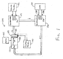
- Figure 1 illustrates schematically a refrigeration system of the present invention.
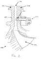
- Figure 2 illustrates a partial sectional view of a centrifugal compressor and diffuser of the present invention.
- Figure 3 illustrates a flow chart for detecting and correcting a rotating stall condition in one embodiment of the present invention.
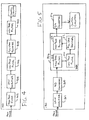
- FIG. 4 illustrates schematically one embodiment of an analog circuit for use with the present invention.
- Figure 5 illustrates schematically one embodiment of a digital circuit for use with the present invention.
- the HVAC, refrigeration or liquid chiller system 100 includes a compressor 108, a condenser 112, a water chiller or evaporator 126, and a control panel 140.
- the control panel 140 receives input signals from the system 100 that indicate the performance of the system 100 and transmits signals to components of the system 100 to control the operation of the system 100.
- the conventional liquid chiller system 100 includes many other features that are not shown in Figure 1 . These features have been purposely omitted to simplify the drawing for ease of illustration.
- Compressor 108 compresses a refrigerant vapor and delivers the vapor to the condenser 112 through a discharge line.
- the compressor 108 is preferably a centrifugal compressor; however, the present invention can be used with any type of compressor that can experience a rotating stall condition or operate at a flow where rotating stall can occur.
- the refrigerant vapor delivered to the condenser 112 enters into a heat exchange relationship with a fluid, e.g. air or water, and undergoes a phase change to a refrigerant liquid as a result of the heat exchange relationship with the fluid.
- the condensed liquid refrigerant from condenser 112 flows to an evaporator 126.
- the refrigerant vapor in the condenser 112 enters into the heat exchange relationship with water, flowing through a heat-exchanger coil 116 connected to a cooling tower 122.
- the refrigerant vapor in the condenser 112 undergoes a phase change to a refrigerant liquid as a result of the heat exchange relationship with the water in the heat-exchanger coil 116.
- the evaporator 126 can preferably include a heat-exchanger coil 128 having a supply line 128S and a return line 128R connected to a cooling load 130.
- the heat-exchanger coil 128 can include a plurality of tube bundles within the evaporator 126.
- a secondary liquid which is preferably water, but can be any other suitable secondary liquid, e.g. ethylene, calcium chloride brine or sodium chloride brine, travels into the evaporator 126 via return line 128R and exits the evaporator 126 via supply line 128S.
- the liquid refrigerant in the evaporator 126 enters into a heat exchange relationship with the secondary liquid in the heat-exchanger coil 128 to chill the temperature of the secondary liquid in the heat-exchanger coil 128.
- the refrigerant liquid in the evaporator 126 undergoes a phase change to a refrigerant vapor as a result of the heat exchange relationship with the secondary liquid in the heat-exchanger coil 128.
- the vapor refrigerant in the evaporator 126 exits the evaporator 126 and returns to the compressor 108 by a suction line to complete the cycle.
- system 100 has been described in terms of preferred embodiments for the condenser 112 and evaporator 126, it is to be understood that any suitable configuration of condenser 112 and evaporator 126 can be used in system 100, provided that the appropriate phase change of the refrigerant in the condenser 112 and evaporator 126 is obtained.
- pre-rotation vanes or inlet guide vanes 120 that control the flow of refrigerant to the compressor 108.
- An actuator is used to open the pre-rotation vanes 120 to increase the amount of refrigerant to the compressor 108 and thereby increase the cooling capacity of the system 100.
- an actuator is used to close the pre-rotation vanes 120 to decrease the amount of refrigerant to the compressor 108 and thereby decrease the cooling capacity of the system 100.
- the system 100 includes a motor or drive mechanism 152 for compressor 108.
- motor is used with respect to the drive mechanism for the compressor 108, it is to be understood that the term “motor” is not limited to a motor but is intended to encompass any component that can be used in conjunction with the driving of motor 152, such as a variable speed drive and a motor starter.
- the motor or drive mechanism 152 is an electric motor and associated components.
- other drive mechanisms such as steam or gas turbines or engines and associated components can be used to drive the compressor 108.
- FIG. 2 illustrates a partial sectional view of the compressor 108 of a preferred embodiment of the present invention.
- the compressor 108 includes an impeller 202 for compressing the refrigerant vapor.
- the compressed vapor then passes through a diffuser 119.
- the diffuser 119 is preferably a vaneless radial diffuser and has a diffuser space 204 formed between a diffuser plate 206 and a nozzle base plate 208 for the passage of the refrigerant vapor.
- the nozzle base plate 208 is configured for use with a diffuser ring 210.
- the diffuser ring 210 is used to control the velocity of refrigerant vapor that passes through the diffuser passage 202.
- the diffuser ring 210 can be extended into the diffuser passage 202 to increase the velocity of the vapor flowing through the passage and can be retracted from the diffuser passage 202 to decrease the velocity of the vapor flowing through the passage.
- the diffuser ring 210 can be extended and retracted using an adjustment mechanism 212.
- the system 100 also includes a sensor 160 for sensing an operating condition of system 100 that can be used to determine a rotating stall condition in the diffuser 119.
- the sensor 160 can be placed anywhere in the gas flow path downstream of the impeller 202 of the compressor 108. However, the sensor 160 is preferably positioned in the compressor discharge passage (as shown schematically in Figure 1 ) or the diffuser 119.
- the sensor 160 is preferably a pressure transducer for measuring an acoustic or sound pressure phenomenon, however, other types of sensors may also be employed.
- an accelerometer can be used to measure stall related vibration.
- the pressure transducer generates a signal that is representative of the stall energies present in the discharge line.
- the signal from the sensor 160 is transferred over a line to the control panel 140 for subsequent processing to determine and correct rotating stall in the diffuser 119.
- the output of sensor 160 used to measure the energy associated with rotating stall is preferably conditioned so as to differentiate between stall-related acoustic energy and energy due to other sources of sound or vibration.
- the conditioning can occur by simply measuring the amount of energy within a range of frequencies that includes the fundamental stall frequency and its major harmonics. In other conditioning schemes, some frequencies within the stall-related region that are not related to stall could be sensed and removed from the analysis in order to enhance the ability to detect the presence of only rotating stall energies.
- the conditioned output signal from sensor 160 can be used in conjunction with the process discussed below to take corrective action to avoid significant amounts of rotating stall noise being generated by the compressor 108.
- FIG 3 illustrates one process for detecting and correcting rotating stall in the diffuser 119 of the compressor 108.
- the process can be implemented on the control panel 140 using analog components (a portion of which is shown schematically in Figure 4 ), digital components (a portion of which is shown schematically in Figure 5 ) or a combination of analog and digital components (not shown).
- the process begins at step 302 with the control panel 140 receiving a signal from sensor 160.
- the signal received from sensor 160 corresponds to an amount of energy which may indicate the onset of rotating stall.
- the direct measurement of the sound pressure phenomenon with the pressure transducer 160 in the preferred embodiment provides a more reliable indication of the existence of rotating stall and avoids other, non-stall related acoustic signals.
- any vibration due to the unbalance of the compressor's motor 152, or gear, or impeller 202 which may be in the same frequency range as the rotating stall noise can provide signals of such magnitudes that they may interfere with the ability to detect only the rotating stall noise related components.
- the signal from sensor 160 is passed through a high pass filter.
- the high pass filter is used to remove the DC portion of the signal.
- the high pass filter preferably has a break frequency of about 10 Hz.
- the break frequency can be set to any appropriate value that removes the DC portion of the signal while leaving a sufficient AC portion of the signal for analysis depending the desired accuracy of the detection.
- the high pass filter can include a single pole RC high pass filter which results in an input signal attenuation of 0.707 at 10 Hz which decreases below this frequency to zero at DC (0 Hertz).
- higher order high pass filters can be used for filtering the signal from the sensor 160.
- the signal After passing through the high pass filter and a gain amplifier (if necessary), the signal is then passed through a low pass filter in step 306.
- the low pass filter is used to attenuate frequencies above a break or cutoff frequency, which break frequency defines the upper frequency level associated with rotating stall conditions.
- the upper frequency or break frequency associated with rotating stall energy is about 300 Hz.
- a six order Butterworth low pass filter is used to eliminate frequency components above the stall frequency range (approximately 10-300 Hz) not related to rotating stall which could result in a false indication of rotating stall.
- different order, preferably larger order, low pass filters can be used to remove the higher frequencies.
- steps 304 and 306 can be combined into a single step.
- a band pass filter instead of using both a high pass filter (step 304) and a low pass filter (step 306), a band pass filter can be used to remove both the DC component and the higher frequencies from the sensor signal.
- the band pass filter preferably has a frequency range of about 10-300 Hz, which is the equivalent frequency range after the high pass and low pass filters of steps 304 and 306.
- the signal After passing through the low pass filter in step 306, the signal is passed through an active full wave rectifier in step 308.
- the active full wave rectifier is used to convert or "flip" the negative portions of the AC signal to an equivalent positive value while having no impact on the positive portion of the AC signal.
- the full wave rectified signal has only positive components and includes a composite of AC components superimposed on DC components.
- the composite signal yields an average (or DC) value which increases in magnitude as the energies at the stall frequencies increase in amplitude.
- the signal from the active full wave rectifier is passed through a low pass filter having a low cutoff frequency to pass only the DC component.
- the DC component portion of the full wave rectified waveform provides a representation of the stall fluctuation amplitude of the sensor 160, thus only the DC component of the signal is necessary for the detection of rotating stall.
- the low pass filter can have a cutoff frequency of 0.16 Hz. However, this frequency is not critical and other cutoff frequencies, e.g., 0.1 Hz, can be used for passing only the DC component.
- FIG 4 illustrates schematically an analog circuit for completing steps 304-310.
- a high pass filter 402 receives the signal from sensor 160, which high pass filter 402 filters the signal as described with regard to step 304.
- a gain amplifier 404 can be used to boost or strengthen the output from the high pass filter 402.
- the gain amplifier 404 can be used to boost the signal from the high pass filter 402 to an appropriate value for comparison to a threshold value representative of a rotating stall condition.
- a low pass filter 406 receives a signal from the gain amplifier 404 or the high pass filter 402 and filters the signal as described above with regard to step 306.
- An active full wave rectifier 408 is used to rectify the signal from the low pass filter 406 as described above with regard to step 308.
- An active full wave rectifier 408 is preferred in order to eliminate DC offsets that may be created by using a full wave bridge rectifier.
- the full wave rectified signal from the active full wave rectifier 408 is filtered using a low pass filter 410, which filters the signal as described above with regard to step 310 and sends a signal to control circuitry, which control circuitry may include a microprocessor and/or comparator, for subsequent processing of the signal from the low pass filter 410.
- FIG. 5 illustrates schematically a digital circuit for completing steps 304-310.
- a gain amplifier 502 can be used to boost or strengthen the signal from sensor 160 to an appropriate value for comparison to a threshold value representative of a rotating stall condition.
- the signal from gain amplifier 502 or the sensor 160 is then passed through an A/D converter 504 to convert the analog signal to a digital signal.
- the digital signal from the A/D converter 504 is then preferably provided to digital signal processor (DSP) circuitry 506 for completing steps 304-310.
- DSP digital signal processor
- a high pass filter 508 receives the signal from A/D converter 504, which high pass filter 508 filters the signal as described with regard to step 304.
- a low pass filter 510 receives a signal from the high pass filter 508 and filters the signal as described with regard to step 306.
- a full wave rectifier 512 is used to rectify the signal from the low pass filter 510 as described with regard to step 308.
- the full wave rectified signal from the full wave rectifier 512 is filtered using a low pass filter 514, which filters the signal as described with regard to step 310.
- the signal from the low pass filter 514 of DSP circuitry 506 is then passed through a D/A converter 516, which generates an analog signal and sends the analog signal to control circuitry, which may include a microprocessor and/or comparator, for subsequent processing of the analog signal.
- the low pass filtered signal having only a DC component from step 310 is then compared with a threshold value to determine the presence of rotating stall in step 312.
- a threshold value can be set to a value equal to a multiple of the normal operating value for the DC component, i.e., the value of the DC component when there is no rotating stall.
- the threshold value can be two to six times the normal operating value.
- the threshold values for detecting rotating stall can be between 0.8-1.2 VDC.
- the values for normal operation and threshold are dependent on the amount of gain that is applied to the signal. In other words, when more gain is applied to a signal, the normal operating value will be larger and the threshold value will be larger. If rotating stall is not detected in step 312, the process returns to step 302 and a new signal from sensor 160 is obtained for processing.
- Corrective action can include, but is not limited to, narrowing the width of the diffuser space 204 of the radial diffuser 119, shortening the length of the radial diffuser 119, or increasing flow to the compressor 108 at the compressor inlet or downstream of the impeller 202.
- the control panel 140 upon the detection of rotating stall the control panel 140 sends a signal to the diffuser 119 and specifically, adjustment mechanism 212 of the diffuser 119 to adjust the position of the diffuser ring 210 to correct the rotating stall condition.
- the diffuser ring 210 is inserted into the diffuser space 204 to narrow the width of the diffuser space 204 in order to correct the rotating stall condition.
Landscapes
- Engineering & Computer Science (AREA)
- Mechanical Engineering (AREA)
- General Engineering & Computer Science (AREA)
- Control Of Positive-Displacement Air Blowers (AREA)
- Structures Of Non-Positive Displacement Pumps (AREA)
Abstract
Claims (25)
- Procédé de rectification du décollement rotatif dans un diffuseur radial (119) d'un compresseur centrifuge (108), le procédé comprenant les étapes consistant à :mesurer, dans le diffuseur radial (119) ou en aval du diffuseur dans le passage de décharge du compresseur centrifuge (108), une valeur représentative de l'énergie acoustique associée au décollement rotatif (302) dans ledit diffuseur radial ;filtrer la valeur mesurée à l'aide d'un filtre passe-bande afin d'obtenir une valeur filtrée (304, 306) ;redresser la valeur filtrée à l'aide d'un redresseur pleine onde (408, 512) afin d'obtenir une valeur redressée (308) ;filtrer la valeur redressée à l'aide d'un filtre passe-bas (410, 514) afin d'obtenir une composante d'énergie de décollement (310) ;comparer la composante d'énergie de décollement à une valeur prédéterminée afin de déterminer le décollement rotatif dans le diffuseur radial (119), cas dans lequel le décollement rotatif est présent dans le diffuseur radial (119) lorsque la composante d'énergie de décollement est supérieure à la valeur prédéterminée (312) ; etenvoyer un signal de commande au compresseur centrifuge (108) afin d'ajuster une configuration opérationnelle du compresseur centrifuge (108) en réaction à une détermination du décollement rotatif (314).
- Procédé selon la revendication 1, l'étape de filtrage de la valeur mesurée à l'aide d'un filtre passe-bande (304, 306) englobant les étapes consistant à :filtrer la valeur mesurée à l'aide d'un filtre passe-haut (402, 508) ayant une fréquence de rupture de 10 Hz afin d'obtenir une valeur intermédiaire (304) ; etfiltrer la valeur intermédiaire à l'aide d'un filtre passe-bas (406, 510) ayant une fréquence de rupture de 300 Hz (306).
- Procédé selon la revendication 2, le filtre passe-haut (402) étant un filtre passe-haut RC à un seul pôle et le filtre passe-bas (406) étant un filtre passe-bas de Butterworth de sixième ordre.
- Procédé selon la revendication 2, comprenant en outre l'étape consistant à amplifier la valeur intermédiaire à l'aide d'un amplificateur de gain (404).
- Procédé selon la revendication 1, le redresseur pleine onde (408) étant un redresseur pleine onde actif.
- Procédé selon la revendication 1, l'étape de filtrage de la valeur redressée à l'aide d'un filtre passe-bas afin d'obtenir une composante d'énergie de décollement (310) englobant les étapes consistant à filtrer la valeur redressée à l'aide d'un filtre passe-bas (410) ayant une fréquence de coupure de 0,16 Hz.
- Procédé selon la revendication 1, la valeur prédéterminée étant un multiple de la composante d'énergie de décollement calculée pendant le fonctionnement normal du compresseur centrifuge (108) sans décollement rotatif.
- Procédé selon la revendication 1, l'étape d'envoi d'un signal de commande au compresseur centrifuge (108) englobant l'étape consistant à envoyer un signal de commande au diffuseur radial (119).
- Procédé selon la revendication 1, comprenant en outre l'étape de conditionnement de la valeur mesurée afin de supprimer les énergies acoustiques non associées au décollement rotatif.
- Procédé selon la revendication 1, l'étape de mesure d'une valeur représentative de l'énergie acoustique associée au décollement rotatif (302) englobant l'étape consistant à mesurer une pression acoustique dans un diffuseur radial (119) du compresseur centrifuge (108) à l'aide d'un transducteur de pression.
- Procédé selon la revendication 10, le transducteur de pression étant positionné dans un passage de décharge du compresseur.
- Procédé selon la revendication 8, comprenant en outre l'étape de réglage d'une bague de diffuseur afin de rétrécir une largeur d'un espace de diffusion (204) dans le diffuseur radial (119) en réaction au fait que le signal de commande génère est envoyé au diffuseur radial (119).
- Procédé selon la revendication 1, comprenant en outre l'étape d'amplification de la valeur mesurée à l'aide d'un amplificateur de gain (502).
- Système comprenant :un compresseur centrifuge (108) muni d'un diffuseur radial (119) ;un capteur (160) lequel est positionné dans ledit diffuseur (119) ou en aval dudit diffuseur dans le passage de décharge dudit compresseur, qui mesure un paramètre représentatif de l'énergie acoustique associée au décollement rotatif dans ledit diffuseur radial (119) et génère un signal de capteur qui correspond au paramètre mesuré ;un filtre passe-haut (402, 508) ayant une fréquence de rupture de 10 Hz, le filtre passe-haut (402, 508) étant configuré de façon à recevoir le signal de capteur et à produire un signal filtré passe-haut ;un premier filtre passe-bas (406, 510) ayant une fréquence de rupture de 300 Hz, le premier filtre passe-bas (406, 510) étant configuré de façon à recevoir le signal filtré passe-liaut à partir du filtre passe-haut (402, 508) et à produire un signal filtré passe-bas ;un redresseur pleine onde (408, 512), le redresseur pleine onde (408, 512) étant configuré de façon à recevoir le signal filtré passe-bas et à produire un signal redressé ;un deuxième filtre passe-bas (410, 514), le deuxième filtre passe-bas (410, 514), étant configuré de façon à recevoir le signal redressé et à produire un signal de composante d'énergie de décollement ; etdes circuits de commande, les circuits de commande étant configurés de façon à déterminer le décollement rotatif dans le diffuseur radial (119) en utilisant le signal de composante d'énergie de décollement et à produire un signal de commande afin d'ajuster une configuration opérationnelle du compresseur centrifuge (108) en réaction à une détermination du décollement rotatif.
- Système selon la revendication 14, le filtre passe-haut (402) étant un filtre passe-haut RC à un seul pôle.
- Système selon la revendication 14, le premier filtre passe-bas (406) étant un filtre passe-bas de Butterworth de sixième ordre.
- Système selon la revendication 14 comprenant en outre un amplificateur de gain (404), l'amplificateur de gain (404) étant configuré de façon à recevoir le signal filtré passe-haut et à présenter un signal amplifié au premier filtre passe-bas (406).
- Système selon la revendication 14, le redresseur pleine onde (408) étant un redresseur pleine onde actif.
- Système selon la revendication 14, le deuxième filtre passe-bas (410, 514) ayant une fréquence de rupture de 0,16 Hz.
- Système selon la revendication 14 comprenant en outre :un convertisseur analogique/numérique (504) afin de convertir le signal de capteur en un signal numérique ;un processeur de signaux numériques (506), le processeur de signaux numériques (506) recevant le signal numérique à partir du convertisseur analogique/numérique (504), et le processeur de signaux numériques comprenant :le filtre passe-haut (508), le filtre passe-haut (508) étant configuré de façon à recevoir le signal numérique ;le premier filtre passe-bas (510),le redresseur pleine onde (512),le deuxième filtre passe-bas (514) etun convertisseur numérique/analogique (516) pour convertir le signal de composante d'énergie de décollement en un signal analogique ; etles circuits de commande étant configurés de façon à déterminer le décollement rotatif dans le diffuseur radial (119) en utilisant le signal analogique.
- Système selon la revendication 14 ou 20, le capteur (160) comprenant un transducteur de pression afin de mesurer une pression acoustique dans le diffuseur radial (119) du compresseur centrifuge (108).
- Système selon la revendication 21, le transducteur de pression étant disposé dans un passage de décharge du compresseur centrifuge (108) lors de l'installation du transducteur de pression.
- Système selon la revendication 20 comprenant en outre un amplificateur de gain (502), l'amplificateur de gain (502) étant configuré de façon à recevoir le paramètre mesuré et à présenter un signal amplifié au convertisseur analogique/numérique (504).
- Système selon la revendication 14 ou 20,
les circuits de commande comprenant un comparateur destiné à comparer le signal de composante d'énergie de décollement à une valeur prédéterminée ;
les circuits de commande produisant le signal de commande en réaction au fait que le signal de composante d'énergie de décollement est supérieur à la valeur prédéterminée ; et
la valeur prédéterminée étant un multiple de la composante d'énergie de décollement calculée pendant le fonctionnement normal du compresseur centrifuge (108) sans décollement rotatif. - Procédé selon la revendication 7 ou système selon la revendication 24, la valeur prédéterminée étant égale à 2 à 6 fois la valeur de la composante d'énergie de décollement calculée pendant le fonctionnement normal du compresseur centrifuge (108) sans décollement rotatif.
Applications Claiming Priority (3)
| Application Number | Priority Date | Filing Date | Title |
|---|---|---|---|
| US40537402P | 2002-08-23 | 2002-08-23 | |
| US405374P | 2002-08-23 | ||
| PCT/US2003/025378 WO2004018880A1 (fr) | 2002-08-23 | 2003-08-14 | Systeme et procede de detection du decollement rotatif dans un compresseur centrifuge |
Publications (2)
| Publication Number | Publication Date |
|---|---|
| EP1540188A1 EP1540188A1 (fr) | 2005-06-15 |
| EP1540188B1 true EP1540188B1 (fr) | 2011-04-20 |
Family
ID=31946864
Family Applications (1)
| Application Number | Title | Priority Date | Filing Date |
|---|---|---|---|
| EP03793048A Expired - Lifetime EP1540188B1 (fr) | 2002-08-23 | 2003-08-14 | Systeme et procede de detection du decollement rotatif dans un compresseur centrifuge |
Country Status (10)
| Country | Link |
|---|---|
| US (1) | US6857845B2 (fr) |
| EP (1) | EP1540188B1 (fr) |
| JP (1) | JP4017631B2 (fr) |
| KR (1) | KR100667599B1 (fr) |
| CN (2) | CN100350158C (fr) |
| AU (1) | AU2003258214A1 (fr) |
| CA (1) | CA2493197C (fr) |
| DE (1) | DE60336827D1 (fr) |
| TW (1) | TWI233467B (fr) |
| WO (1) | WO2004018880A1 (fr) |
Families Citing this family (45)
| Publication number | Priority date | Publication date | Assignee | Title |
|---|---|---|---|---|
| US7905102B2 (en) * | 2003-10-10 | 2011-03-15 | Johnson Controls Technology Company | Control system |
| US7356999B2 (en) * | 2003-10-10 | 2008-04-15 | York International Corporation | System and method for stability control in a centrifugal compressor |
| US7326027B1 (en) * | 2004-05-25 | 2008-02-05 | The United States Of America As Represented By The Administrator Of The National Aeronautics And Space Administration | Devices and methods of operation thereof for providing stable flow for centrifugal compressors |
| DE102004044185A1 (de) | 2004-09-13 | 2006-03-30 | Avicomp Controls Gmbh | Verfahren und Vorrichtung zum Ermitteln eines Fehlerzustandes eines rotierenden Verdichters |
| US7578659B2 (en) * | 2005-01-31 | 2009-08-25 | York International Corporation | Compressor discharge muffler |
| US7398186B2 (en) * | 2005-08-17 | 2008-07-08 | Xtek, Inc. | Data acquisition system for system monitoring |
| NO324581B1 (no) * | 2006-01-26 | 2007-11-26 | Dynatrend As | Fremgangsmate og anordning for a kunne bestemme nar det forekommer roterende stall i en kompressors turbinblad II |
| US7824147B2 (en) * | 2006-05-16 | 2010-11-02 | United Technologies Corporation | Airfoil prognosis for turbine engines |
| DE102006034478A1 (de) * | 2006-07-26 | 2008-01-31 | Oerlikon Leybold Vacuum Gmbh | Verfahren zur Ermittlung einer Aussage über einen Zustand einer Turbomolekularpumpe sowie eine Turbomolekularpumpe |
| US7798777B2 (en) * | 2006-12-15 | 2010-09-21 | General Electric Company | Engine compressor assembly and method of operating the same |
| US7905702B2 (en) * | 2007-03-23 | 2011-03-15 | Johnson Controls Technology Company | Method for detecting rotating stall in a compressor |
| US8204701B2 (en) * | 2007-06-15 | 2012-06-19 | United Technologies Corporation | Aeroelastic model using the principal shapes of modes (AMPS) |
| DE102007035712B4 (de) * | 2007-07-30 | 2009-12-17 | Siemens Ag | Verfahren zum Erkennen eines Störfalles "Rotating Stall" bei einem umrichtergespeisten Verdichter |
| US7895003B2 (en) * | 2007-10-05 | 2011-02-22 | Emerson Climate Technologies, Inc. | Vibration protection in a variable speed compressor |
| US8459053B2 (en) | 2007-10-08 | 2013-06-11 | Emerson Climate Technologies, Inc. | Variable speed compressor protection system and method |
| BE1017905A3 (nl) * | 2007-10-29 | 2009-11-03 | Atlas Copco Airpower Nv | Werkwijze voor het vermijden van een onstabiele werkingstoestand bij centrifugaalcompressoren en centrifugaalcompressor voorzien van middelen waarmee zulke werkwijze automatisch wordt toegepast. |
| TWI437167B (zh) * | 2007-10-31 | 2014-05-11 | Johnson Controls Tech Co | 控制系統 |
| US7650777B1 (en) * | 2008-07-18 | 2010-01-26 | General Electric Company | Stall and surge detection system and method |
| US11378088B2 (en) | 2009-06-05 | 2022-07-05 | Johnson Controls Tyco IP Holdings LLP | Control system for centrifugal compressor |
| US9500553B2 (en) * | 2009-11-09 | 2016-11-22 | Kulite Semiconductor Products, Inc. | Systems and methods for improved dynamic pressure measurements |
| GB2468571B (en) * | 2010-03-01 | 2011-01-26 | Flakt Woods Ltd | A method of detecting and controlling stall in an axial fan |
| FR2962500B1 (fr) * | 2010-07-08 | 2012-09-14 | Snecma | Procede et dispositif de detection d'un decollement tournant affectant un compresseur de turbomachine |
| CN103814261B (zh) * | 2011-09-14 | 2016-06-15 | 丹佛斯公司 | 离心压缩机的扩散器控制 |
| ITCO20110056A1 (it) | 2011-12-02 | 2013-06-03 | Nuovo Pignone Spa | Metodo ed apparecchiatura per rilevare stallo rotativo e compressore |
| EP2618002B1 (fr) * | 2012-01-17 | 2016-05-04 | ABB Technology Oy | Procédé pour détecter le sens de rotation correct d'un appareil centrifuge et ensemble formant l'appareil centrifuge |
| US9624936B2 (en) | 2012-05-16 | 2017-04-18 | Compressor Controls Corporation | Turbocompressor antisurge control by vibration monitoring |
| US8854626B2 (en) | 2012-07-20 | 2014-10-07 | Prime Photonics, Lc | Rotating stall detection using optical measurement of blade untwist |
| EP2885543B1 (fr) | 2012-08-17 | 2019-01-16 | Dresser-Rand Company | Système et procédé de détection de décrochage ou pompage dans des compresseurs radiaux |
| EP3171034B1 (fr) * | 2012-11-09 | 2020-10-07 | Johnson Controls Technology Company | Diffuseur à géométrie variable doté de déplacement étendu |
| US9823005B2 (en) | 2013-01-25 | 2017-11-21 | Trane International Inc. | Methods and systems for detecting and recovering from control instability caused by impeller stall |
| CN103216461B (zh) * | 2013-04-17 | 2016-01-13 | 南京航空航天大学 | 轴流式压气机的失速先兆识别方法 |
| CN103511314A (zh) * | 2013-10-08 | 2014-01-15 | 无锡杰尔压缩机有限公司 | 一种喘振传感器 |
| US9188133B1 (en) * | 2015-01-09 | 2015-11-17 | Borgwarner Inc. | Turbocharger compressor active diffuser |
| EP3045676A1 (fr) * | 2015-01-13 | 2016-07-20 | Siemens Aktiengesellschaft | Procédé destiné à éviter un détachement de courant rotatif |
| CN105485039B (zh) * | 2015-12-11 | 2017-05-10 | 中国北方发动机研究所(天津) | 基于动态压力测量的压气机失速测试结构及测试方法 |
| CN106321465A (zh) * | 2016-08-22 | 2017-01-11 | 江苏大学 | 一种离心泵叶轮旋转失速的动力学表征方法 |
| EP3312432B1 (fr) | 2016-10-19 | 2021-06-23 | IFP Energies nouvelles | Diffuseur pour dispositif de compression de fluide, comprenant au moins une aube avec ouverture |
| TWI855391B (zh) | 2017-09-25 | 2024-09-11 | 美商江森自控技術公司 | 用於離心壓縮機之擴散器系統及用於用來壓縮流體的可變容量離心壓縮機之系統 |
| KR102102805B1 (ko) | 2018-03-14 | 2020-04-22 | 두산중공업 주식회사 | 고장 감지 장치 및 가스터빈 |
| CN110360130B (zh) | 2018-04-09 | 2022-12-27 | 开利公司 | 可变扩压器驱动系统 |
| US10690081B2 (en) * | 2018-04-23 | 2020-06-23 | Fca Us Llc | Diagnostic techniques for a surge valve of a turbocharged engine |
| US11206743B2 (en) | 2019-07-25 | 2021-12-21 | Emerson Climate Technolgies, Inc. | Electronics enclosure with heat-transfer element |
| CN110925233A (zh) * | 2019-12-05 | 2020-03-27 | 中国航发四川燃气涡轮研究院 | 一种基于声学信号的压气机喘振故障诊断方法 |
| CN112632719B (zh) * | 2020-12-11 | 2022-05-17 | 哈尔滨工程大学 | 一种基于一维平均流线法的多级轴流压气机特性校正方法 |
| KR102566306B1 (ko) * | 2021-11-04 | 2023-08-11 | 현대위아 주식회사 | 선택적으로 개폐되는 냉각 유로를 구비한 모터 냉각 구조 |
Family Cites Families (32)
| Publication number | Priority date | Publication date | Assignee | Title |
|---|---|---|---|---|
| US4573358A (en) | 1984-10-22 | 1986-03-04 | Westinghouse Electric Corp. | Turbine blade vibration detection apparatus |
| US4581900A (en) | 1984-12-24 | 1986-04-15 | Borg-Warner Corporation | Method and apparatus for detecting surge in centrifugal compressors driven by electric motors |
| US5082421A (en) * | 1986-04-28 | 1992-01-21 | Rolls-Royce Plc | Active control of unsteady motion phenomena in turbomachinery |
| US4967550A (en) * | 1987-04-28 | 1990-11-06 | Rolls-Royce Plc | Active control of unsteady motion phenomena in turbomachinery |
| KR920005348Y1 (ko) | 1988-03-01 | 1992-08-03 | 미쓰비시전기주식회사 | 압력센서 |
| US4971516A (en) | 1988-05-04 | 1990-11-20 | Exxon Research & Engineering Company | Surge control in compressors |
| JP2865834B2 (ja) | 1990-09-05 | 1999-03-08 | 株式会社日立製作所 | 遠心圧縮機 |
| US5097711A (en) | 1990-10-29 | 1992-03-24 | Westinghouse Electric Corp. | Shrouded turbine blade vibration monitor and target therefor |
| JP2743658B2 (ja) | 1991-10-21 | 1998-04-22 | 株式会社日立製作所 | 遠心圧縮機 |
| WO1994003862A1 (fr) | 1992-08-10 | 1994-02-17 | Dow Deutschland Inc. | Procede et dispositif de controle et de regulation d'un compresseur |
| EP0654163B1 (fr) | 1992-08-10 | 2000-07-26 | Dow Deutschland Inc. | Procede et dispositif permettant de surveiller l'excitation vibratoire d'un compresseur axial |
| JPH06147189A (ja) | 1992-11-11 | 1994-05-27 | Hitachi Ltd | 圧縮機の旋回失速防止装置 |
| EP0673505A1 (fr) | 1992-12-08 | 1995-09-27 | Skf Condition Monitoring, Inc. | Systeme d'amelioration de l'enveloppe pour la detection des mesures de vibration anormales |
| US5448881A (en) | 1993-06-09 | 1995-09-12 | United Technologies Corporation | Gas turbine engine control based on inlet pressure distortion |
| US5726891A (en) | 1994-01-26 | 1998-03-10 | Sisson; Patterson B. | Surge detection system using engine signature |
| CA2149576A1 (fr) | 1994-05-19 | 1995-11-20 | Hideomi Harada | Dispositif de detection de surtension et turbomachines connexes |
| US5618160A (en) | 1994-05-23 | 1997-04-08 | Ebara Corporation | Turbomachinery with variable angle fluid guiding devices |
| US5851103A (en) | 1994-05-23 | 1998-12-22 | Ebara Corporation | Turbomachinery with variable angle fluid guiding devices |
| WO1997000381A1 (fr) | 1994-12-14 | 1997-01-03 | United Technologies Corporation | Limitation du decrochage tournant et des cretes dans un compresseur, a l'aide de mesures d'asymetrie d'ecoulement d'air |
| US5719791A (en) | 1995-03-17 | 1998-02-17 | Georgia Tech Research Corporation | Methods, apparatus and systems for real time identification and control of modes of oscillation |
| US5746062A (en) | 1996-04-11 | 1998-05-05 | York International Corporation | Methods and apparatuses for detecting surge in centrifugal compressors |
| US5984625A (en) | 1996-10-15 | 1999-11-16 | California Institute Of Technology | Actuator bandwidth and rate limit reduction for control of compressor rotating stall |
| US6098010A (en) | 1997-11-20 | 2000-08-01 | The Regents Of The University Of California | Method and apparatus for predicting and stabilizing compressor stall |
| US6092029A (en) | 1998-02-19 | 2000-07-18 | Bently Nevada Corporation | Method and apparatus for diagnosing and controlling rotating stall and surge in rotating machinery |
| US6139262A (en) | 1998-05-08 | 2000-10-31 | York International Corporation | Variable geometry diffuser |
| US6036432A (en) | 1998-07-09 | 2000-03-14 | Carrier Corporation | Method and apparatus for protecting centrifugal compressors from rotating stall vibrations |
| US6010303A (en) * | 1998-08-05 | 2000-01-04 | United Technologies Corporation | Apparatus and method of predicting aerodynamic and aeromechanical instabilities in turbofan engines |
| US6354071B2 (en) | 1998-09-25 | 2002-03-12 | General Electric Company | Measurement method for detecting and quantifying combustor dynamic pressures |
| US6195982B1 (en) | 1998-12-30 | 2001-03-06 | United Technologies Corporation | Apparatus and method of active flutter control |
| US6298718B1 (en) | 2000-03-08 | 2001-10-09 | Cummins Engine Company, Inc. | Turbocharger compressor diagnostic system |
| US6536284B2 (en) * | 2001-06-12 | 2003-03-25 | General Electric Company | Method and apparatus for compressor control and operation via detection of stall precursors using frequency demodulation of acoustic signatures |
| CN2545370Y (zh) * | 2002-06-13 | 2003-04-16 | 中国科学院工程热物理研究所 | 拓宽多级、轴流压气机稳定运行区域的装置 |
-
2003
- 2003-08-14 US US10/641,277 patent/US6857845B2/en not_active Expired - Lifetime
- 2003-08-14 DE DE60336827T patent/DE60336827D1/de not_active Expired - Lifetime
- 2003-08-14 CN CNB038196077A patent/CN100350158C/zh not_active Expired - Lifetime
- 2003-08-14 EP EP03793048A patent/EP1540188B1/fr not_active Expired - Lifetime
- 2003-08-14 CA CA002493197A patent/CA2493197C/fr not_active Expired - Fee Related
- 2003-08-14 AU AU2003258214A patent/AU2003258214A1/en not_active Abandoned
- 2003-08-14 KR KR1020057002777A patent/KR100667599B1/ko not_active Expired - Fee Related
- 2003-08-14 WO PCT/US2003/025378 patent/WO2004018880A1/fr not_active Ceased
- 2003-08-14 JP JP2004530997A patent/JP4017631B2/ja not_active Expired - Fee Related
- 2003-08-14 CN CN2007101028305A patent/CN101082344B/zh not_active Expired - Lifetime
- 2003-08-22 TW TW092123146A patent/TWI233467B/zh not_active IP Right Cessation
Also Published As
| Publication number | Publication date |
|---|---|
| AU2003258214A1 (en) | 2004-03-11 |
| CA2493197C (fr) | 2008-06-03 |
| KR20050050089A (ko) | 2005-05-27 |
| US20040037693A1 (en) | 2004-02-26 |
| KR100667599B1 (ko) | 2007-01-16 |
| EP1540188A1 (fr) | 2005-06-15 |
| CA2493197A1 (fr) | 2004-03-04 |
| CN100350158C (zh) | 2007-11-21 |
| CN1675470A (zh) | 2005-09-28 |
| US6857845B2 (en) | 2005-02-22 |
| JP4017631B2 (ja) | 2007-12-05 |
| DE60336827D1 (de) | 2011-06-01 |
| WO2004018880A1 (fr) | 2004-03-04 |
| TW200406544A (en) | 2004-05-01 |
| TWI233467B (en) | 2005-06-01 |
| CN101082344B (zh) | 2010-06-16 |
| CN101082344A (zh) | 2007-12-05 |
| JP2005535834A (ja) | 2005-11-24 |
Similar Documents
| Publication | Publication Date | Title |
|---|---|---|
| EP1540188B1 (fr) | Systeme et procede de detection du decollement rotatif dans un compresseur centrifuge | |
| US8337144B2 (en) | Method for detecting rotating stall in a compressor | |
| US5913248A (en) | Surge detection device and turbomachinery therewith | |
| EP2438304B1 (fr) | Système de commande | |
| JP2000513430A (ja) | ファジィ論理を用いた遠心型冷却機の可変速度制御 | |
| NO754197L (fr) | ||
| US9823005B2 (en) | Methods and systems for detecting and recovering from control instability caused by impeller stall | |
| US7293954B2 (en) | Centrifugal compressor for turbo chiller, turbo chiller, and control method therefor | |
| JPH01394A (ja) | 圧縮機のサ−ジング防止装置 | |
| JP3110258B2 (ja) | 非対称遠心圧縮機ディフューザによるサージ検知装置 | |
| JPH07117075B2 (ja) | ターボ圧縮機におけるサージング検出装置 | |
| JPH0819918B2 (ja) | ターボ冷凍機のサージング防止装置 | |
| JPH03213696A (ja) | 圧縮機の旋回失速防止装置 | |
| Smith et al. | Experiences with nonsynchronous forced vibration in centrifugal compressors | |
| JPH0658295A (ja) | 圧縮機の制御装置 |
Legal Events
| Date | Code | Title | Description |
|---|---|---|---|
| PUAI | Public reference made under article 153(3) epc to a published international application that has entered the european phase |
Free format text: ORIGINAL CODE: 0009012 |
|
| 17P | Request for examination filed |
Effective date: 20050117 |
|
| AK | Designated contracting states |
Kind code of ref document: A1 Designated state(s): AT BE BG CH CY CZ DE DK EE ES FI FR GB GR HU IE IT LI LU MC NL PT RO SE SI SK TR |
|
| AX | Request for extension of the european patent |
Extension state: AL LT LV MK |
|
| DAX | Request for extension of the european patent (deleted) | ||
| RBV | Designated contracting states (corrected) |
Designated state(s): DE FR GB |
|
| 17Q | First examination report despatched |
Effective date: 20100526 |
|
| GRAP | Despatch of communication of intention to grant a patent |
Free format text: ORIGINAL CODE: EPIDOSNIGR1 |
|
| GRAS | Grant fee paid |
Free format text: ORIGINAL CODE: EPIDOSNIGR3 |
|
| GRAA | (expected) grant |
Free format text: ORIGINAL CODE: 0009210 |
|
| AK | Designated contracting states |
Kind code of ref document: B1 Designated state(s): DE FR GB |
|
| REG | Reference to a national code |
Ref country code: GB Ref legal event code: FG4D |
|
| REF | Corresponds to: |
Ref document number: 60336827 Country of ref document: DE Date of ref document: 20110601 Kind code of ref document: P |
|
| REG | Reference to a national code |
Ref country code: DE Ref legal event code: R096 Ref document number: 60336827 Country of ref document: DE Effective date: 20110601 |
|
| PLBE | No opposition filed within time limit |
Free format text: ORIGINAL CODE: 0009261 |
|
| STAA | Information on the status of an ep patent application or granted ep patent |
Free format text: STATUS: NO OPPOSITION FILED WITHIN TIME LIMIT |
|
| 26N | No opposition filed |
Effective date: 20120123 |
|
| REG | Reference to a national code |
Ref country code: DE Ref legal event code: R097 Ref document number: 60336827 Country of ref document: DE Effective date: 20120123 |
|
| PGFP | Annual fee paid to national office [announced via postgrant information from national office to epo] |
Ref country code: GB Payment date: 20130816 Year of fee payment: 11 Ref country code: FR Payment date: 20130821 Year of fee payment: 11 |
|
| PGFP | Annual fee paid to national office [announced via postgrant information from national office to epo] |
Ref country code: DE Payment date: 20131016 Year of fee payment: 11 |
|
| REG | Reference to a national code |
Ref country code: DE Ref legal event code: R119 Ref document number: 60336827 Country of ref document: DE |
|
| GBPC | Gb: european patent ceased through non-payment of renewal fee |
Effective date: 20140814 |
|
| REG | Reference to a national code |
Ref country code: DE Ref legal event code: R119 Ref document number: 60336827 Country of ref document: DE Effective date: 20150303 |
|
| REG | Reference to a national code |
Ref country code: FR Ref legal event code: ST Effective date: 20150430 |
|
| PG25 | Lapsed in a contracting state [announced via postgrant information from national office to epo] |
Ref country code: DE Free format text: LAPSE BECAUSE OF NON-PAYMENT OF DUE FEES Effective date: 20150303 Ref country code: GB Free format text: LAPSE BECAUSE OF NON-PAYMENT OF DUE FEES Effective date: 20140814 |
|
| PG25 | Lapsed in a contracting state [announced via postgrant information from national office to epo] |
Ref country code: FR Free format text: LAPSE BECAUSE OF NON-PAYMENT OF DUE FEES Effective date: 20140901 |