EP1540246B1 - Appareil de nettoyage - Google Patents
Appareil de nettoyage Download PDFInfo
- Publication number
- EP1540246B1 EP1540246B1 EP03798132A EP03798132A EP1540246B1 EP 1540246 B1 EP1540246 B1 EP 1540246B1 EP 03798132 A EP03798132 A EP 03798132A EP 03798132 A EP03798132 A EP 03798132A EP 1540246 B1 EP1540246 B1 EP 1540246B1
- Authority
- EP
- European Patent Office
- Prior art keywords
- cleaning appliance
- appliance according
- steam
- heat insulation
- insulation part
- Prior art date
- Legal status (The legal status is an assumption and is not a legal conclusion. Google has not performed a legal analysis and makes no representation as to the accuracy of the status listed.)
- Expired - Lifetime
Links
- 238000004140 cleaning Methods 0.000 title claims abstract description 55
- 238000009413 insulation Methods 0.000 claims abstract description 31
- 238000005192 partition Methods 0.000 claims description 12
- 239000000463 material Substances 0.000 claims 1
- 238000000465 moulding Methods 0.000 claims 1
- 230000002093 peripheral effect Effects 0.000 claims 1
- 229920003023 plastic Polymers 0.000 claims 1
- 239000004033 plastic Substances 0.000 claims 1
- 239000003570 air Substances 0.000 description 20
- 238000010438 heat treatment Methods 0.000 description 9
- 239000012080 ambient air Substances 0.000 description 3
- 230000002349 favourable effect Effects 0.000 description 3
- 239000012530 fluid Substances 0.000 description 3
- 230000005855 radiation Effects 0.000 description 3
- 230000015572 biosynthetic process Effects 0.000 description 2
- 238000001704 evaporation Methods 0.000 description 2
- 238000009434 installation Methods 0.000 description 2
- 238000004519 manufacturing process Methods 0.000 description 2
- 238000010137 moulding (plastic) Methods 0.000 description 2
- 238000004804 winding Methods 0.000 description 2
- 239000012459 cleaning agent Substances 0.000 description 1
- 230000017525 heat dissipation Effects 0.000 description 1
- 239000012774 insulation material Substances 0.000 description 1
- 239000007788 liquid Substances 0.000 description 1
- XLYOFNOQVPJJNP-UHFFFAOYSA-N water Substances O XLYOFNOQVPJJNP-UHFFFAOYSA-N 0.000 description 1
Images


Classifications
-
- B—PERFORMING OPERATIONS; TRANSPORTING
- B08—CLEANING
- B08B—CLEANING IN GENERAL; PREVENTION OF FOULING IN GENERAL
- B08B3/00—Cleaning by methods involving the use or presence of liquid or steam
-
- F—MECHANICAL ENGINEERING; LIGHTING; HEATING; WEAPONS; BLASTING
- F22—STEAM GENERATION
- F22B—METHODS OF STEAM GENERATION; STEAM BOILERS
- F22B1/00—Methods of steam generation characterised by form of heating method
- F22B1/28—Methods of steam generation characterised by form of heating method in boilers heated electrically
-
- B—PERFORMING OPERATIONS; TRANSPORTING
- B08—CLEANING
- B08B—CLEANING IN GENERAL; PREVENTION OF FOULING IN GENERAL
- B08B2230/00—Other cleaning aspects applicable to all B08B range
- B08B2230/01—Cleaning with steam
Definitions
- the invention relates to a cleaning device with a housing which surrounds a steam generator, wherein the steam generator comprises an electrically heatable steam boiler for generating steam, which can be applied to a surface to be cleaned, and a heat insulating member surrounding the boiler at least partially.
- the steam generator comprises an electrically heatable steam boiler for generating steam, which can be applied to a surface to be cleaned, and a heat insulating member surrounding the boiler at least partially.
- Such cleaning devices are used for cleaning a wide variety of surfaces, especially hard surfaces, for example, for cleaning floor surfaces used. They comprise a steam generator with an electrically heatable steam boiler for evaporating a liquid cleaning agent, for example for evaporating water. The steam thus generated can be applied to the surface to be cleaned.
- the electrically heatable steam boiler leads during operation of the cleaning device to a considerable heating of the interior of the housing. This can result in damage to other mechanical or electrical components of the cleaning device. To avoid unacceptably high temperatures in the housing interior, it is therefore customary to wrap the steam boiler with an insulating mat. However, the achievable thermal insulation of the boiler is limited.
- Object of the present invention is therefore to develop a cleaning device of the type mentioned in such a way that it has an improved thermal insulation of the boiler and is inexpensive to produce.
- the heat insulating member has a rigid wall and surrounds the boiler at least partially forming a gap between a wall of the heat insulating member and the boiler.
- the heat insulating member has a rigid wall which is positioned at a distance from the steam boiler, so that on the one hand and by the steam boiler on the other hand, a gap is defined by the wall of the heat insulating part, in which an air cushion is formed, which ensures a very good thermal insulation of the boiler ,
- the heat released from the boiler by heat losses to the environment is given off by convection to a large extent and by radiation to a lesser extent.
- the heat insulation part is placed on the steam boiler.
- the steam boiler thus forms a holder for the heat insulating part, so that additional holding elements can be omitted within the housing for the heat insulating part.
- this ensures that at least the - based on the position of use of the cleaning device - upper side the steam boiler is covered by the heat insulating part and thus in this upper area an air cushion can form in the space between the heat insulating part and the boiler. Since the heated air from the boiler rises upward, a very good thermal insulation is ensured by the upper end of the steam generator in the form of heat insulation part.
- the heat insulation part can then cover not only a top of the boiler, but it can also spread over the boiler laterally. This achieves increased thermal shielding.
- the heat insulation part has a plurality of partitions, which divide the intermediate space honeycomb-like. Due to the honeycomb-like subdivision of the intermediate space, a plurality of separate air cushions are formed in the latter, which are in fluid communication with each other only to a very limited extent. Thus, a circulation of the air within the gap is virtually prevented. It has been shown that thus the thermal insulation of the heat insulating part can be further improved.
- the heat insulating part comprises a spaced apart from the steam boiler supporting wall, from which the steam boiler facing underside protrude the intermediate walls.
- the latter can be held on the supporting wall, in particular can be provided that the intermediate walls are integrally connected to the support wall. In the operating position of the cleaning device, the intermediate walls can be aligned substantially vertically, while the support wall is arranged virtually horizontally.
- the heat insulation part comprises a side wall arranged at a distance from the steam boiler, which surrounds the steam boiler at least in regions in the circumferential direction.
- the arrangement of the side wall at a distance from the steam boiler allows the formation of an annular space surrounding the steam boiler, which leads to an improved thermal insulation of the steam generator. It is particularly advantageous in this case if the side wall is aligned substantially vertically in the position of use of the cleaning device.
- the side wall may be integrally connected to the support wall.
- the heat insulation part is designed as a plastic molding. As a result, the production cost of the steam generator can be considerably reduced.
- the heat insulating part forms a support for electrical components, in particular for electrical switching elements, of the cleaning device.
- the heat insulating part thus not only serves the thermal insulation of the steam boiler, but it also serves to establish electrical components, without additional support elements must be provided within the housing. The manufacturing cost of the cleaning device can be further reduced.
- the cleaning device comprises a Jardinaufrollvortechnische with a rotatable cable reel for the automatic winding of an electrical connection cable.
- the handling of the cleaning device is simplified by the electrical connection cable of the cleaning device can be rolled up in a simple manner by means of an incoming roll-up spring.
- a considerable electric current which leads to self-heating of the cable winder.
- this self-heating does not impair the device function in the cleaning device according to the invention, since the further heat source, namely the steam generator, is thermally very well insulated by the use of the heat-insulating part.
- the cable reeling device is positioned adjacent to a bottom wall of the housing of the cleaning device.
- the arrangement of the cable reeling device below the steam generator ensures that ambient air heated by heat losses of the steam generator flows in the direction away from the cable reeling device, namely upwards, and thus does not lead to additional heating of the cable reeling device.
- a particularly low overall height of the cleaning device can be achieved in that the axis of rotation of the cable roller is vertically aligned in the operating position of the cleaning device.
- the cable retractor disposed within the housing is configured substantially in the form of a cylinder, wherein the cylinder axis is predetermined by the axis of rotation of the cable reel.
- the cylinder is in this case made relatively flat, so that despite the arrangement of the cable winder below the steam generator results in a low overall height for the cleaning device according to the invention.
- a partition wall is arranged between the steam generator and the cable winder.
- the partition wall forms a radiation shield so that thermal radiation emanating from the steam generator is reflected to a not inconsiderable proportion by the partition wall, thereby reducing the heating of the cable reeling device.
- the partition has at least one opening.
- Such an opening can form an air flow originating from the cable reeling device upwards within the housing. In this way, heated air can flow upwards out of the area of the cable reel from the cable reeling device. It is advantageous if the housing above the partition air outlet openings, so that the heated air can be discharged to the outside.
- the cable reel has two spaced-apart cheeks, which receive between them the electrical connection cable and which are aligned parallel to the partition wall.
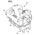
- a generally designated by the reference numeral 10 cleaning device is shown with a housing 12 which surrounds an interior 14 in which a steam generator 16 with a steam boiler 18 and a heat insulating member in the form of an insulating hood 20 are arranged.
- the steam boiler 18 is connected via known per se and therefore not shown in the drawing electrical connecting lines with a disposed within the housing 12 below the steam generator 16
- Jardinauerauervorraum 22 having a rotatably mounted within the housing 12 cable reel 24 for automatically winding a known per se and Therefore, in the drawing, not shown electrical connection cable which can be introduced via a housing opening 26 in the two spaced-apart cheeks 27, 29 limited area of the cable roller 24.
- a partition wall 30 having an opening 32.
- the region of the cable reeling device 22 is in fluid communication with the region of the interior 14 surrounding the steam generator 16 via the opening 32.
- the cleaning device 10 also includes a per se known and therefore not shown in the drawing for clarity in the drawing, which is in fluid communication with the boiler 18 in the usual manner and at the free end of a cleaning nozzle can be attached, so that within the boiler 18 generated steam on the steam line and the cleaning nozzle on the surface to be cleaned, for example, a hard surface, preferably a bottom surface, can be applied.
- the steam boiler 18 is formed in two parts and comprises a lower boiler part 34 and a boiler shell 36, which are screwed vapor-tightly together via bolts, not shown in the drawing.
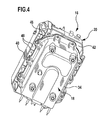
- the integrally formed as a rigid plastic molding insulating cover 20 20 engages over the boiler shell and includes a in the use position of the cleaning device 10 horizontally aligned Supporting wall 38, of which a side wall 40 surrounding the boiler shell 36 in the circumferential direction and arranged at a distance from the boiler shell 36 projects vertically downwards. Between the side wall 40 and the steam boiler 18 thus extends an open at the bottom annular space 42nd
- the support wall 38 is disposed at a distance from the steam boiler 18, wherein from the steam boiler 18 facing bottom 44 of the support wall 38 projecting a plurality of vertically aligned intermediate walls 46 down, forming a total of a honeycomb-like structure with a plurality of underside open air chambers 48th , which are each separated by partitions 46 from each other. This becomes clear in particular from FIG.
- the air chambers 48 form a gap which is limited on the one hand by the support wall 38 and the side wall 40 and on the other hand by the boiler shell 36 of the boiler 18 and an air cushion is formed for thermal insulation of the boiler 18.
- the partitions 46 form no circulating air flow, and also the air exchange between the area surrounding the steam generator 16 of the inner space 14 and the above-mentioned gap is greatly reduced.
- the steam generator 16 is characterized by a very good thermal insulation. This makes it possible to position within the housing 12 in addition to the steam generator 16, a further heat source in the form of Jardinaufrollvoriques 22. This is subject to considerable self-heating due to the current that is within the cable reel 24 on that in the drawing not shown electrical connection cable flows. It should be noted that the cable is usually unwound during operation of the cleaning device 10 only a part of the cable reel. Much of the heat generated by the cable winder 22 is dissipated to the ambient air below the dividing wall 30, and the heated air can flow through the opening 32 into the area above the dividing wall 30. About known per se and therefore not shown in the drawing air outlet openings, which are formed in the housing 12, the heated air can be discharged to the outside, while fresh air (not shown) can enter into the housing 12 via molded into the bottom wall 28 air inlet openings.
- the Jardinaufrollvortechnische 22 Since the Jardinaufrollvoriques 22 is disposed below the steam generator, it is subject to virtually no noticeable heating by the steam generator 16, because by heat loss of the steam generator 16 heated ambient air also flows upwards, ie in the cable reeling device 22 opposite direction. An additional heating of the cable winder 22 by the heat loss of the steam generator 16 is thus avoided.
Landscapes
- Engineering & Computer Science (AREA)
- Life Sciences & Earth Sciences (AREA)
- Sustainable Development (AREA)
- Sustainable Energy (AREA)
- Physics & Mathematics (AREA)
- Thermal Sciences (AREA)
- Mechanical Engineering (AREA)
- General Engineering & Computer Science (AREA)
- Cleaning By Liquid Or Steam (AREA)
- Dry Shavers And Clippers (AREA)
- Electrical Discharge Machining, Electrochemical Machining, And Combined Machining (AREA)
- Manufacturing Of Electric Cables (AREA)
Claims (14)
- Appareil de nettoyage comportant un boîtier (12) qui entoure un générateur de vapeur (16), le générateur de vapeur (16) comportant une chaudière à vapeur (18) pouvant être chauffée par des moyens électriques afin de générer de la vapeur qui peut être appliquée sur une surface à nettoyer, ainsi qu'une pièce d'isolation thermique (20) qui entoure la chaudière à vapeur (18) au moins par portions, caractérisé en ce que la pièce d'isolation thermique (20) comporte une paroi rigide (38, 40) et entoure la chaudière à vapeur (18) au moins par portions en ménageant un espace intermédiaire (42, 48) entre une paroi (38, 40) de la pièce d'isolation thermique (20) et la chaudière à vapeur (18).
- Appareil de nettoyage selon la revendication 1, caractérisé en ce que la pièce d'isolation thermique (20) est montée sur la chaudière à vapeur (18).
- Appareil de nettoyage selon la revendication 1 ou 2, caractérisé en ce que la pièce d'isolation thermique (20) a la forme d'un capot.
- Appareil de nettoyage selon la revendication 1, 2 ou 3, caractérisé en ce que la pièce d'isolation thermique (20) comporte une pluralité de parois intermédiaires (46) qui divisent l'espace intermédiaire de façon alvéolaire.
- Appareil de nettoyage selon la revendication 4, caractérisé en ce que la pièce d'isolation thermique (20) comporte une paroi porteuse (38) qui est placée à distance de la chaudière à vapeur (18), et de la partie inférieure (44) de laquelle, dirigée vers la chaudière à vapeur (18), saillent les parois intermédiaires (46).
- Appareil de nettoyage selon l'une des revendications précédentes, caractérisé en ce que la pièce d'isolation thermique (20) comporte une paroi latérale (40) qui est placée à distance de la chaudière à vapeur (18), et qui entoure la chaudière à vapeur (18) au moins par portions dans une direction circonférentielle.
- Appareil de nettoyage selon l'une des revendications précédentes, caractérisé en ce que la pièce d'isolation thermique (20) forme un support destiné à des composants électriques, notamment des éléments de commutation électrique, de l'appareil de nettoyage (10).
- Appareil de nettoyage selon l'une des revendications précédentes, caractérisé en ce que la pièce d'isolation thermique (20) est conformée en une pièce de matière plastique moulée.
- Appareil de nettoyage selon l'une des revendications précédentes, caractérisé en ce que l'appareil de nettoyage (10) comporte un dispositif d'enroulement de câble (22) comportant un rouleau de câble rotatif (24) pour l'enroulement automatique d'un câble de raccordement électrique.
- Appareil de nettoyage selon la revendication 9, caractérisé en ce que le dispositif d'enroulement de câble (22) est disposé au-dessous du générateur de vapeur (16).
- Appareil de nettoyage selon la revendication 9 ou 10, caractérisé en ce que l'axe de rotation du rouleau de câble (24) est orienté verticalement dans la position d'utilisation de l'appareil de nettoyage (10).
- Appareil de nettoyage selon la revendication 9, 10 ou 11, caractérisé en ce qu'une paroi de séparation (30) est agencée entre le générateur de vapeur (16) et le dispositif d'enroulement de câble (22).
- Appareil de nettoyage selon la revendication 12, caractérisé en ce que la paroi de séparation (30) comporte au moins une ouverture (32).
- Appareil de nettoyage selon la revendication 12 ou 13, caractérisé en ce que le rouleau de câble (24) comporte deux joues distantes l'une de l'autre, qui sont orientées parallèlement à la paroi de séparation (30) et qui reçoivent entre elles le câble de raccordement électrique.
Applications Claiming Priority (3)
| Application Number | Priority Date | Filing Date | Title |
|---|---|---|---|
| DE10245012A DE10245012B3 (de) | 2002-09-20 | 2002-09-20 | Reinigungsgerät |
| DE10245012 | 2002-09-20 | ||
| PCT/EP2003/009467 WO2004029509A1 (fr) | 2002-09-20 | 2003-08-27 | Appareil de nettoyage |
Publications (3)
| Publication Number | Publication Date |
|---|---|
| EP1540246A1 EP1540246A1 (fr) | 2005-06-15 |
| EP1540246B1 true EP1540246B1 (fr) | 2006-07-26 |
| EP1540246B8 EP1540246B8 (fr) | 2006-10-04 |
Family
ID=31984120
Family Applications (1)
| Application Number | Title | Priority Date | Filing Date |
|---|---|---|---|
| EP03798132A Expired - Lifetime EP1540246B8 (fr) | 2002-09-20 | 2003-08-27 | Appareil de nettoyage |
Country Status (5)
| Country | Link |
|---|---|
| EP (1) | EP1540246B8 (fr) |
| AT (1) | ATE334342T1 (fr) |
| AU (1) | AU2003258670A1 (fr) |
| DE (1) | DE10245012B3 (fr) |
| WO (1) | WO2004029509A1 (fr) |
Families Citing this family (1)
| Publication number | Priority date | Publication date | Assignee | Title |
|---|---|---|---|---|
| US20080282995A1 (en) * | 2005-07-28 | 2008-11-20 | Koninklijke Philips Electronics N.V. | Assembly of a Housing and a Steam Generator Device |
Family Cites Families (4)
| Publication number | Priority date | Publication date | Assignee | Title |
|---|---|---|---|---|
| US2785272A (en) * | 1955-04-25 | 1957-03-12 | Hal H Baly | Steam generator |
| US2886689A (en) * | 1958-04-15 | 1959-05-12 | Garth Harold | Steam generator |
| DE4309241A1 (de) * | 1993-03-23 | 1994-09-29 | Wagner Gmbh J | Vorrichtung zum Ablösen von Tapeten |
| DE20201959U1 (de) * | 2002-02-08 | 2002-06-06 | Kable Enterprises Co., Ltd., Taipeh/T'ai-pei | Dampfreinigungsvorrichtung |
-
2002
- 2002-09-20 DE DE10245012A patent/DE10245012B3/de not_active Expired - Fee Related
-
2003
- 2003-08-27 AU AU2003258670A patent/AU2003258670A1/en not_active Abandoned
- 2003-08-27 AT AT03798132T patent/ATE334342T1/de not_active IP Right Cessation
- 2003-08-27 EP EP03798132A patent/EP1540246B8/fr not_active Expired - Lifetime
- 2003-08-27 WO PCT/EP2003/009467 patent/WO2004029509A1/fr not_active Ceased
Also Published As
| Publication number | Publication date |
|---|---|
| EP1540246A1 (fr) | 2005-06-15 |
| EP1540246B8 (fr) | 2006-10-04 |
| ATE334342T1 (de) | 2006-08-15 |
| WO2004029509A1 (fr) | 2004-04-08 |
| AU2003258670A1 (en) | 2004-04-19 |
| DE10245012B3 (de) | 2004-04-08 |
Similar Documents
| Publication | Publication Date | Title |
|---|---|---|
| DE1429926C3 (de) | Elektrisches Röstgerät | |
| DE102017210633B4 (de) | Batteriepackung | |
| DE29615089U1 (de) | Bürstenloser Gleichstromlüfter | |
| EP0333906B1 (fr) | Résistance chauffante à coefficient de température positif | |
| DE7907457U1 (de) | Tauchfaehige, elektrische heizvorrichtung | |
| EP2466222A1 (fr) | Dispositif de chauffage électrique | |
| EP1540246B1 (fr) | Appareil de nettoyage | |
| WO1988009911A1 (fr) | Accumulateur de chaleur, en particulier pour systemes de chauffage de vehicules a moteur alimentes par la chaleur perdue du moteur | |
| DE29906894U1 (de) | Einsetzstruktur einer Ölsammelplatte für einen Elektro-Ofen | |
| DE19609535A1 (de) | Destilliervorrichtung | |
| DE2614564A1 (de) | Verfahren und vorrichtung zur steuerung des verhaeltnisses strahlung- konvektion bei heizgeraeten | |
| EP4016783B1 (fr) | Chargeur pourvu d'unité d'électronique de charge et structure de guidage d'air de refroidissement | |
| DE3332309A1 (de) | Geraet zum raclettieren, grillen oder ueberbacken | |
| DE2751991A1 (de) | Kocheinheit mit einer von abgeflachten rohrheizkoerpern gebildeten kochflaeche | |
| DE10019238A1 (de) | Wasserkocher mit einstellbarer Wassertemperatur | |
| DE2451130C3 (de) | Dampfdruckgargerät für Speisen | |
| DE60320353T2 (de) | Gekühlter Elektronikschrank, insbesondere für Fernsprechanlagen | |
| EP0023532B1 (fr) | Unité d'émetteur radar | |
| DE1464641A1 (de) | Elektrische Vorrichtung mit Kuehlanordnung | |
| DE10203615B4 (de) | Backofenmuffel | |
| DE3408856A1 (de) | Warmwasserboiler | |
| DE1579819A1 (de) | Elektrischer Waermespeicher | |
| CH667357A5 (de) | Raumheizgeraet. | |
| DE202024105506U1 (de) | Heißluftfritteuse mit hinterliegender Heißluftvorrichtung zum Blasen der Heißluft nach vorne | |
| DE3427459A1 (de) | Geschlossenes oelgefaess fuer elektrische geraete |
Legal Events
| Date | Code | Title | Description |
|---|---|---|---|
| PUAI | Public reference made under article 153(3) epc to a published international application that has entered the european phase |
Free format text: ORIGINAL CODE: 0009012 |
|
| 17P | Request for examination filed |
Effective date: 20050129 |
|
| AK | Designated contracting states |
Kind code of ref document: A1 Designated state(s): AT BE BG CH CY CZ DK EE ES FI FR GB GR HU IE IT LI LU MC NL PT RO SE SI SK TR |
|
| AX | Request for extension of the european patent |
Extension state: AL LT LV MK |
|
| DAX | Request for extension of the european patent (deleted) | ||
| GRAP | Despatch of communication of intention to grant a patent |
Free format text: ORIGINAL CODE: EPIDOSNIGR1 |
|
| GRAS | Grant fee paid |
Free format text: ORIGINAL CODE: EPIDOSNIGR3 |
|
| GRAA | (expected) grant |
Free format text: ORIGINAL CODE: 0009210 |
|
| AK | Designated contracting states |
Kind code of ref document: B1 Designated state(s): AT BE BG CH CY CZ DK EE ES FI FR GB GR HU IE IT LI LU MC NL PT RO SE SI SK TR |
|
| PG25 | Lapsed in a contracting state [announced via postgrant information from national office to epo] |
Ref country code: CZ Free format text: LAPSE BECAUSE OF FAILURE TO SUBMIT A TRANSLATION OF THE DESCRIPTION OR TO PAY THE FEE WITHIN THE PRESCRIBED TIME-LIMIT Effective date: 20060726 Ref country code: RO Free format text: LAPSE BECAUSE OF FAILURE TO SUBMIT A TRANSLATION OF THE DESCRIPTION OR TO PAY THE FEE WITHIN THE PRESCRIBED TIME-LIMIT Effective date: 20060726 Ref country code: GB Free format text: LAPSE BECAUSE OF FAILURE TO SUBMIT A TRANSLATION OF THE DESCRIPTION OR TO PAY THE FEE WITHIN THE PRESCRIBED TIME-LIMIT Effective date: 20060726 Ref country code: FI Free format text: LAPSE BECAUSE OF FAILURE TO SUBMIT A TRANSLATION OF THE DESCRIPTION OR TO PAY THE FEE WITHIN THE PRESCRIBED TIME-LIMIT Effective date: 20060726 Ref country code: SK Free format text: LAPSE BECAUSE OF FAILURE TO SUBMIT A TRANSLATION OF THE DESCRIPTION OR TO PAY THE FEE WITHIN THE PRESCRIBED TIME-LIMIT Effective date: 20060726 Ref country code: SI Free format text: LAPSE BECAUSE OF FAILURE TO SUBMIT A TRANSLATION OF THE DESCRIPTION OR TO PAY THE FEE WITHIN THE PRESCRIBED TIME-LIMIT Effective date: 20060726 Ref country code: IE Free format text: LAPSE BECAUSE OF FAILURE TO SUBMIT A TRANSLATION OF THE DESCRIPTION OR TO PAY THE FEE WITHIN THE PRESCRIBED TIME-LIMIT Effective date: 20060726 |
|
| REG | Reference to a national code |
Ref country code: GB Ref legal event code: FG4D Free format text: NOT ENGLISH |
|
| REG | Reference to a national code |
Ref country code: CH Ref legal event code: NV Representative=s name: ISLER & PEDRAZZINI AG Ref country code: CH Ref legal event code: EP |
|
| REG | Reference to a national code |
Ref country code: IE Ref legal event code: FG4D Free format text: LANGUAGE OF EP DOCUMENT: GERMAN |
|
| PG25 | Lapsed in a contracting state [announced via postgrant information from national office to epo] |
Ref country code: BE Free format text: LAPSE BECAUSE OF NON-PAYMENT OF DUE FEES Effective date: 20060831 Ref country code: MC Free format text: LAPSE BECAUSE OF NON-PAYMENT OF DUE FEES Effective date: 20060831 |
|
| PG25 | Lapsed in a contracting state [announced via postgrant information from national office to epo] |
Ref country code: SE Free format text: LAPSE BECAUSE OF FAILURE TO SUBMIT A TRANSLATION OF THE DESCRIPTION OR TO PAY THE FEE WITHIN THE PRESCRIBED TIME-LIMIT Effective date: 20061026 Ref country code: BG Free format text: LAPSE BECAUSE OF FAILURE TO SUBMIT A TRANSLATION OF THE DESCRIPTION OR TO PAY THE FEE WITHIN THE PRESCRIBED TIME-LIMIT Effective date: 20061026 Ref country code: DK Free format text: LAPSE BECAUSE OF FAILURE TO SUBMIT A TRANSLATION OF THE DESCRIPTION OR TO PAY THE FEE WITHIN THE PRESCRIBED TIME-LIMIT Effective date: 20061026 |
|
| PG25 | Lapsed in a contracting state [announced via postgrant information from national office to epo] |
Ref country code: ES Free format text: LAPSE BECAUSE OF FAILURE TO SUBMIT A TRANSLATION OF THE DESCRIPTION OR TO PAY THE FEE WITHIN THE PRESCRIBED TIME-LIMIT Effective date: 20061106 |
|
| PG25 | Lapsed in a contracting state [announced via postgrant information from national office to epo] |
Ref country code: PT Free format text: LAPSE BECAUSE OF FAILURE TO SUBMIT A TRANSLATION OF THE DESCRIPTION OR TO PAY THE FEE WITHIN THE PRESCRIBED TIME-LIMIT Effective date: 20061226 |
|
| GBV | Gb: ep patent (uk) treated as always having been void in accordance with gb section 77(7)/1977 [no translation filed] |
Effective date: 20060726 |
|
| REG | Reference to a national code |
Ref country code: IE Ref legal event code: FD4D |
|
| ET | Fr: translation filed | ||
| PLBE | No opposition filed within time limit |
Free format text: ORIGINAL CODE: 0009261 |
|
| STAA | Information on the status of an ep patent application or granted ep patent |
Free format text: STATUS: NO OPPOSITION FILED WITHIN TIME LIMIT |
|
| 26N | No opposition filed |
Effective date: 20070427 |
|
| REG | Reference to a national code |
Ref country code: CH Ref legal event code: PCAR Free format text: ISLER & PEDRAZZINI AG;POSTFACH 1772;8027 ZUERICH (CH) |
|
| PG25 | Lapsed in a contracting state [announced via postgrant information from national office to epo] |
Ref country code: AT Free format text: LAPSE BECAUSE OF NON-PAYMENT OF DUE FEES Effective date: 20060827 |
|
| BERE | Be: lapsed |
Owner name: ALFRED KARCHER G.M.B.H. & CO. KG Effective date: 20060831 |
|
| PG25 | Lapsed in a contracting state [announced via postgrant information from national office to epo] |
Ref country code: GR Free format text: LAPSE BECAUSE OF FAILURE TO SUBMIT A TRANSLATION OF THE DESCRIPTION OR TO PAY THE FEE WITHIN THE PRESCRIBED TIME-LIMIT Effective date: 20061027 |
|
| PG25 | Lapsed in a contracting state [announced via postgrant information from national office to epo] |
Ref country code: EE Free format text: LAPSE BECAUSE OF FAILURE TO SUBMIT A TRANSLATION OF THE DESCRIPTION OR TO PAY THE FEE WITHIN THE PRESCRIBED TIME-LIMIT Effective date: 20060726 |
|
| PG25 | Lapsed in a contracting state [announced via postgrant information from national office to epo] |
Ref country code: HU Free format text: LAPSE BECAUSE OF FAILURE TO SUBMIT A TRANSLATION OF THE DESCRIPTION OR TO PAY THE FEE WITHIN THE PRESCRIBED TIME-LIMIT Effective date: 20070127 Ref country code: TR Free format text: LAPSE BECAUSE OF FAILURE TO SUBMIT A TRANSLATION OF THE DESCRIPTION OR TO PAY THE FEE WITHIN THE PRESCRIBED TIME-LIMIT Effective date: 20060726 Ref country code: LU Free format text: LAPSE BECAUSE OF NON-PAYMENT OF DUE FEES Effective date: 20060827 |
|
| PG25 | Lapsed in a contracting state [announced via postgrant information from national office to epo] |
Ref country code: CY Free format text: LAPSE BECAUSE OF FAILURE TO SUBMIT A TRANSLATION OF THE DESCRIPTION OR TO PAY THE FEE WITHIN THE PRESCRIBED TIME-LIMIT Effective date: 20060726 |
|
| PGFP | Annual fee paid to national office [announced via postgrant information from national office to epo] |
Ref country code: NL Payment date: 20140809 Year of fee payment: 12 Ref country code: CH Payment date: 20140812 Year of fee payment: 12 |
|
| PGFP | Annual fee paid to national office [announced via postgrant information from national office to epo] |
Ref country code: FR Payment date: 20140808 Year of fee payment: 12 |
|
| PGFP | Annual fee paid to national office [announced via postgrant information from national office to epo] |
Ref country code: IT Payment date: 20140820 Year of fee payment: 12 |
|
| REG | Reference to a national code |
Ref country code: CH Ref legal event code: PL |
|
| PG25 | Lapsed in a contracting state [announced via postgrant information from national office to epo] |
Ref country code: LI Free format text: LAPSE BECAUSE OF NON-PAYMENT OF DUE FEES Effective date: 20150831 Ref country code: IT Free format text: LAPSE BECAUSE OF NON-PAYMENT OF DUE FEES Effective date: 20150827 Ref country code: CH Free format text: LAPSE BECAUSE OF NON-PAYMENT OF DUE FEES Effective date: 20150831 |
|
| REG | Reference to a national code |
Ref country code: NL Ref legal event code: MM Effective date: 20150901 |
|
| REG | Reference to a national code |
Ref country code: FR Ref legal event code: ST Effective date: 20160429 |
|
| PG25 | Lapsed in a contracting state [announced via postgrant information from national office to epo] |
Ref country code: NL Free format text: LAPSE BECAUSE OF NON-PAYMENT OF DUE FEES Effective date: 20150901 |
|
| PG25 | Lapsed in a contracting state [announced via postgrant information from national office to epo] |
Ref country code: FR Free format text: LAPSE BECAUSE OF NON-PAYMENT OF DUE FEES Effective date: 20150831 |