EP1540866B1 - Verfahren und vorrichtung zum zuverlässigen übermitteln von informationspaketen in einem drahtlosen kommunikationsnetz - Google Patents
Verfahren und vorrichtung zum zuverlässigen übermitteln von informationspaketen in einem drahtlosen kommunikationsnetz Download PDFInfo
- Publication number
- EP1540866B1 EP1540866B1 EP03788321.2A EP03788321A EP1540866B1 EP 1540866 B1 EP1540866 B1 EP 1540866B1 EP 03788321 A EP03788321 A EP 03788321A EP 1540866 B1 EP1540866 B1 EP 1540866B1
- Authority
- EP
- European Patent Office
- Prior art keywords
- information
- information packet
- wireless
- time
- wireless communication
- Prior art date
- Legal status (The legal status is an assumption and is not a legal conclusion. Google has not performed a legal analysis and makes no representation as to the accuracy of the status listed.)
- Expired - Lifetime
Links
- 238000004891 communication Methods 0.000 title claims description 106
- 238000000034 method Methods 0.000 title claims description 44
- 230000005540 biological transmission Effects 0.000 claims description 73
- 230000006870 function Effects 0.000 claims description 14
- 238000012545 processing Methods 0.000 claims description 9
- 238000011022 operating instruction Methods 0.000 claims description 8
- 230000008569 process Effects 0.000 claims description 7
- 230000004044 response Effects 0.000 claims description 5
- 238000010586 diagram Methods 0.000 description 12
- 238000005259 measurement Methods 0.000 description 10
- 230000008901 benefit Effects 0.000 description 9
- 230000001934 delay Effects 0.000 description 9
- 238000001228 spectrum Methods 0.000 description 5
- 230000015556 catabolic process Effects 0.000 description 3
- 230000001413 cellular effect Effects 0.000 description 3
- 238000006731 degradation reaction Methods 0.000 description 3
- 208000032369 Primary transmission Diseases 0.000 description 2
- 238000005516 engineering process Methods 0.000 description 2
- 238000004519 manufacturing process Methods 0.000 description 2
- 238000012986 modification Methods 0.000 description 2
- 230000004048 modification Effects 0.000 description 2
- 238000012544 monitoring process Methods 0.000 description 2
- 238000013442 quality metrics Methods 0.000 description 2
- 238000011084 recovery Methods 0.000 description 2
- 230000004075 alteration Effects 0.000 description 1
- 125000004122 cyclic group Chemical group 0.000 description 1
- 230000000593 degrading effect Effects 0.000 description 1
- 230000001419 dependent effect Effects 0.000 description 1
- 238000013461 design Methods 0.000 description 1
- 238000011161 development Methods 0.000 description 1
- 230000000694 effects Effects 0.000 description 1
- 238000013213 extrapolation Methods 0.000 description 1
- 230000002349 favourable effect Effects 0.000 description 1
- 230000006872 improvement Effects 0.000 description 1
- 230000000977 initiatory effect Effects 0.000 description 1
- 230000002452 interceptive effect Effects 0.000 description 1
- 230000007246 mechanism Effects 0.000 description 1
- 238000010295 mobile communication Methods 0.000 description 1
- 230000000737 periodic effect Effects 0.000 description 1
- 230000003252 repetitive effect Effects 0.000 description 1
- 230000003595 spectral effect Effects 0.000 description 1
- 230000007704 transition Effects 0.000 description 1
Images



Classifications
-
- H—ELECTRICITY
- H04—ELECTRIC COMMUNICATION TECHNIQUE
- H04L—TRANSMISSION OF DIGITAL INFORMATION, e.g. TELEGRAPHIC COMMUNICATION
- H04L1/00—Arrangements for detecting or preventing errors in the information received
- H04L1/12—Arrangements for detecting or preventing errors in the information received by using return channel
- H04L1/16—Arrangements for detecting or preventing errors in the information received by using return channel in which the return channel carries supervisory signals, e.g. repetition request signals
- H04L1/18—Automatic repetition systems, e.g. Van Duuren systems
-
- H—ELECTRICITY
- H04—ELECTRIC COMMUNICATION TECHNIQUE
- H04L—TRANSMISSION OF DIGITAL INFORMATION, e.g. TELEGRAPHIC COMMUNICATION
- H04L1/00—Arrangements for detecting or preventing errors in the information received
- H04L1/12—Arrangements for detecting or preventing errors in the information received by using return channel
- H04L1/16—Arrangements for detecting or preventing errors in the information received by using return channel in which the return channel carries supervisory signals, e.g. repetition request signals
- H04L1/18—Automatic repetition systems, e.g. Van Duuren systems
- H04L1/1867—Arrangements specially adapted for the transmitter end
- H04L1/1893—Physical mapping arrangements
-
- H—ELECTRICITY
- H04—ELECTRIC COMMUNICATION TECHNIQUE
- H04L—TRANSMISSION OF DIGITAL INFORMATION, e.g. TELEGRAPHIC COMMUNICATION
- H04L1/00—Arrangements for detecting or preventing errors in the information received
- H04L1/02—Arrangements for detecting or preventing errors in the information received by diversity reception
-
- H—ELECTRICITY
- H04—ELECTRIC COMMUNICATION TECHNIQUE
- H04L—TRANSMISSION OF DIGITAL INFORMATION, e.g. TELEGRAPHIC COMMUNICATION
- H04L1/00—Arrangements for detecting or preventing errors in the information received
- H04L1/22—Arrangements for detecting or preventing errors in the information received using redundant apparatus to increase reliability
Definitions
- the present invention relates generally to wireless communication networks and, in particular, to reliably communicating information packets in such networks so as to account for bursts of unplanned interference.
- Wireless communication networks are known and come in a variety of forms. Notable networks include cellular telephone networks, classic land mobile radio networks and satellite transmission networks. These networks are typically characterized as wide area networks. More recently, wireless local area networks and wireless home networks have been proposed, and standards, such as Bluetooth and IEEE 802.11, have been introduced to govern the development of wireless equipment for such localized networks.
- wireless home networks will use unlicensed frequency spectrum most likely in the newly opened five Gigahertz (5 GHz) frequency range. Consequently, each wireless home network has the possibility of encountering substantial, unpredictable interference due to the presence of neighboring home networks (e.g., in apartment buildings, condominiums, and town homes) operating on common frequencies. Adding further to the complexity of wireless home networks, such networks will likely be required to support real-time information, such as audio and video services, in such a manner that users of the networks cannot notably distinguish the reception of real-time information (e.g., a cable television signal or a cordless telephone signal) over a wireless home network from the reception of such information over a typical wired or cabled network. In other words, users of wireless home networks will expect the same quality of service with wireless home networks as they currently receive from their wired networks. The provision of such quality of service is rendered quite difficult in an environment of unpredictable interference that can unexpectedly corrupt transmitted information.
- real-time information e.g., a cable television signal or a cordless telephone signal
- Wide area data networks commonly utilize automatic repeat request (ARQ) or selective ARQ (SARQ) schemes in which a transmitting device retransmits unacknowledged or negatively acknowledged data packets or portions thereof to a receiving device over a traffic channel assigned for the data communication in the event that the data packets or the data packet portions are received with errors by the receiving device.
- ARQ automatic repeat request
- SARQ selective ARQ
- a transmitting device retransmits unacknowledged or negatively acknowledged data packets or portions thereof to a receiving device over a traffic channel assigned for the data communication in the event that the data packets or the data packet portions are received with errors by the receiving device.
- ARQ automatic repeat request
- SARQ selective ARQ
- Some cellular networks allocate a group of secondary traffic channels in each cell for emergency use in the event that the signal qualities of primary traffic channels degrade significantly during voice calls.
- the system controller attempts to re-assign the call to one of the secondary traffic channels. If a secondary channel is available, the system controller re-assigns the call to the secondary channel and the call continues; otherwise, the call is dropped or terminated. In either event, the primary traffic channel is de-allocated and becomes available for a new call. While the allocation and use of a secondary traffic channel facilitates continuation of the call, it does not insure the reliability of the transmitted information. That is, any information that is lost during the transition from the primary traffic channel to the secondary traffic channel is never recovered.
- US patent application publication no. US2002/0071407 describes a method for transmitting packet data and side information including a sequence number of the packet data in a CDMA mobile communication system employing a HARQ scheme for performing retransmission in response to a retransmission request message after initial transmission.
- the method comprises transmitting the packet data and the side information over a dedicated channel during the initial transmission and transmitting the packet data and the side information over a common channel during the retransmission.
- the dedicated channel is a dedicated physical channel (DPCH) and the common channel is a physical downlink shared channel (DSCH).
- DPCH dedicated physical channel
- DSCH physical downlink shared channel
- European patent application publication no. EP0735701 describes a switched antenna diversity transmission method and system for use with an ARQ error protection protocol.
- the transmitter includes a first antenna for transmitting the modulated information packets over a first forward channel of a wireless communication medium to a receiver.
- the transmitter further includes a switch for switching from the first antenna to a second antenna for transmitting the information packets over a second forward channel of a wireless communication medium in response to a negative acknowledgment from the receiver transmitted over a feedback channel of the wireless communication medium.
- the present invention encompasses a method and apparatus for reliably communicating information packets in a wireless communication network.
- a first wireless device in the network e.g., a wireless base transceiver station system
- transmits an information packet to a second wireless device in the network e.g., a wireless audio/video device
- the first device determines (e.g., via an acknowledgment received from the second device) whether the information packet was successfully received by the second device. If the information packet was not successfully received by the second device, the first device retransmits the information packet to the second device over a second wireless communication channel.
- the first device transmits a second information packet to the second device over the first channel in an effort to communicate an information sequence to the second device with minimal delay associated with use of a reliable protocol.
- the present invention facilitates reliable communication of real-time information, such as audio and video information, without introducing undesirable delays that could negatively impact the high quality of service typically expected by real-time information users.
- FIG. 1 is a block diagram of a wireless communication network 100 in accordance with the present invention.
- the wireless communication network 100 includes a plurality of wireless devices, such as a wireless base transceiver station (BTS) system 101 and one or more wireless electronic devices 103-107 (five shown for illustration purposes).
- the wireless devices 101-107 communicate information packets in the network 100 over wireless carrier frequencies 109-111, each of which includes one or more wireless communication channels depending on the multiple access scheme utilized in the network 100.
- BTS wireless base transceiver station
- the multiple access scheme used in the network 100 may be any one or more of time division multiple access (TDMA), direct sequence or frequency hopping code division multiple access (CDMA), frequency division multiple access (FDMA), orthogonal frequency division multiplexing (OFDM), opportunity division multiple access (ODMA), a combination of any of the foregoing multiple access technologies, a multiple access technology in which portions of the frequency spectrum to be used are determined by local signal quality measurements and in which multiple portions of the frequency spectrum may be used simultaneously, or any other multiple access or multiplexing methodology or combination thereof.
- the wireless communication network 100 employs a TDMA access scheme that utilizes time division duplex (TDD) wireless channels on each carrier frequency to implement primary and secondary (rescue) channels, as later described.
- TDD time division duplex
- the wireless communication network 100 is preferably a wireless home network or wireless local area network, although the present invention is applicable to any localized or wide area wireless network.
- the wireless electronic devices 103-107 comprise any wireless devices capable of receiving packetized audio, video and/or data information. As illustrated in FIG. 1 , each wireless electronic device 103-107 may comprise any one of the following conventional household electronic devices adapted for wireless transmissions in accordance with the present invention: a conventional cellular or cordless telephone (e.g., wireless device 103), a standard definition or high definition television (e.g., wireless device 104), a computer (e.g., wireless device 105), conventional analog or digital audio equipment (e.g., wireless device 106), and a conventional home appliance (e.g., wireless device 107).
- a preferred wireless electronic device 103-107 is described below with respect to FIG. 3 .
- electronic devices may be adapted for wireless transmissions in accordance with the present invention by incorporating an appropriate processor, transmitter, receiver and antenna into such devices as described in more detail below with respect to FIG. 3 .
- electronic devices may be adapted for wireless use in accordance with the present invention by including a conventional hardware and software interface capable of interacting with a wireless local area network (LAN) card, such as the CISCO AIRONET 350 Series Wireless LAN Adapter that is commercially available from Cisco Systems, Inc. of San Jose, California, United States of America, or some other wireless transceiver card (e.g., any wireless transceiver card that complies with the Personal Computer Memory Card International Association (PCMCIA) standard) and its accompanying software.
- LAN wireless local area network
- PCMCIA Personal Computer Memory Card International Association
- the wireless device 103-107 referred to herein might constitute the LAN or PCMCIA card alone or the combination of the LAN or PCMCIA card and other circuitry of the electronic device depending on the particular hardware and software implementation selected by the wireless device designer.
- the wireless BTS system 101 is preferably coupled to one or more sources of audio, video and/or data information.
- the wireless BTS system 101 may be coupled to a very high speed digital subscriber line (VDSL) service provider for purposes of receiving audio, video, and data from the Internet, a cable termination system (CTS) for purposes of receiving cable and/or pay-per-view television programming, the public switched telephone network (PSTN) for purposes of receiving telephone calls, and a direct satellite system (DSS) for purposes of receiving satellite programming. While not expressly shown in FIG.
- VDSL very high speed digital subscriber line
- CTS cable termination system
- PSTN public switched telephone network
- DSS direct satellite system
- the wireless BTS system 101 may additionally or alternatively be coupled to other sources of audio, video and/or data information, such as an integrated digital services network (ISDN) service provider, an asymmetric or symmetric digital subscriber line (DSL) service provider, a fiber-to-the-home provider, or the like.
- ISDN integrated digital services network
- DSL digital subscriber line
- a preferred embodiment of the wireless BTS system 100 is described below with respect to FIG. 2 .
- FIG. 2 is a block diagram of a wireless BTS system 101 in accordance with the present invention.
- the wireless BTS system 101 includes, inter alia , a controller 201, a transmitter 203, a receiver 205, an antenna 206, a program memory 209 for storing operating instructions that are executed by the controller 201, a buffer memory 211, and appropriate hardware and software interfaces 213 to allow the controller 201 to interact with various sources of audio, video and/or data information.
- the wireless BTS system 101 also preferably includes an antenna switch, duplexer, circulator, or other highly isolative means (herein referred to as an "antenna switch/duplexer 207") for intermittently providing information packets from the transmitter to the antenna 206 and from the antenna 206 to the receiver 205.
- the wireless BTS system 101 is preferably an integrated unit containing at least all the elements 201-213 depicted in FIG. 2 .
- the wireless BTS system 101 may comprise a collection of appropriately interconnected units or devices, wherein such units or devices perform functions that are equivalent to the functions performed by the elements 201-213 of the wireless BTS system 101 as described below.
- the controller 201 preferably includes one or more microprocessors, microcontrollers, digital signal processors (DSPs), state machines, logic circuitry, or any other device or devices that process information based on operational or programming instructions.
- Such operational or programming instructions are preferably stored in the program memory 209, which memory 209 may be an integrated circuit (IC) memory chip containing any form of random access memory (RAM) or read only memory (ROM), a floppy disk, a compact disk read only memory (CD-ROM), a hard disk drive, a digital versatile disk (DVD), a flash memory card or any other medium for storing digital information.
- IC integrated circuit
- the controller 201 has one or more of its functions performed by a state machine or logic circuitry
- the memory 209 containing the corresponding operational instructions may be embedded within the state machine or logic circuitry. The operations performed by the controller 201 and the rest of the wireless BTS system 101 are described in detail below.
- the transmitter 203 and the receiver 205 are well-known components of two-way wireless communication devices.
- the transmitter 203 and the receiver 205 enable the wireless BTS system 101 to communicate information packets to and acquire information packets from the other wireless devices 103-107.
- the transmitter 203 and the receiver 205 include appropriate, conventional circuitry to enable digital or analog transmissions over a wireless communication channel.
- the implementations of the transmitter 203 and the receiver 205 depend on the implementation of the wireless BTS system 101.
- the transmitter 203 and the receiver 205 may be implemented as an appropriate wireless modem, or as conventional transmitting and receiving components of two-way wireless devices.
- the wireless modem may be located on a PCMCIA card that may be inserted into the controller 201 to facilitate wireless communications.
- Wireless modems are well known; thus no further discussion of them will be presented except to facilitate an understanding of the present invention.
- the controller 201, the transmitter 203 and the receiver 205 have been artificially partitioned herein to facilitate a better understanding of the present invention.
- the antenna 206 preferably comprises any known or developed structure for radiating and receiving electromagnetic energy in the frequency range containing the wireless carrier frequencies 109-111.
- the buffer memory 211 may be any form of volatile memory, such as RAM, and is used for temporarily storing transmitted information packets in accordance with the present invention.
- the interfaces 213 are conventional hardware and/or software interfaces, including appropriate analog and/or digital modems, amplifiers, filters, encoders, decoders, and so forth, that enable the controller 201 to exchange audio, video and data information, as applicable, with various sources and sinks of such information.
- FIG. 3 is a block diagram of a wireless electronic device 103-107 in accordance with the present invention.
- the wireless device 103-107 includes, inter alia , a processor 301, a transmitter 303, a receiver 305, an antenna 306, a program memory 309 for storing operating instructions that are executed by the processor 301, and a buffer memory 311.
- the wireless device 103-107 also preferably includes an antenna switch, duplexer, circulator, or other highly isolative means (herein referred to as an "antenna switch/duplexer 307") for intermittently providing information packets from the transmitter 303 to the antenna 306 and from the antenna 306 to the receiver 305.
- an antenna switch, duplexer, circulator, or other highly isolative means herein referred to as an "antenna switch/duplexer 307"
- the wireless device 103-107 is preferably an integrated unit containing at least all the elements 301-311 depicted in FIG. 3 , as well as any other elements necessary for the device 103-107 to perform its particular electronic function.
- the wireless device 103-107 may comprise a collection of appropriately interconnected units or devices, wherein such units or devices perform functions that are equivalent to the functions performed by the elements 301-311 of the wireless device 103-107 as described below.
- wireless device 105 may comprise a laptop computer and a wireless LAN card.
- the processor 301 preferably includes one or more microprocessors, microcontrollers, DSPs, state machines, logic circuitry, or any other device or devices that process information based on operational or programming instructions. Such operational or programming instructions are preferably stored in the program memory 309, which memory 309 may be an IC memory chip containing any form of RAM or ROM, a floppy disk, a CD-ROM, a hard disk drive, a DVD, a flash memory card or any other medium for storing digital information.
- the processor 301 has one or more of its functions performed by a state machine or logic circuitry, the memory 309 containing the corresponding operational instructions may be embedded within the state machine or logic circuitry. The operations performed by the processor 301 and the rest of the wireless electronic device 103-107 are described in detail below.
- the transmitter 303 and the receiver 305 are well-known components of two-way wireless communication devices.
- the transmitter 303 and the receiver 305 enable the wireless device 103-107 to communicate information packets to and acquire information packets from the other wireless devices 102-107.
- the transmitter 303 and the receiver 305 include appropriate, conventional circuitry to enable digital or analog transmissions over a wireless communication channel.
- the transmitter 303 and the receiver 305 depend on the implementation of the wireless device 103-107.
- the transmitter 303 and the receiver 305 may be implemented as an appropriate wireless modem, or as conventional transmitting and receiving components of two-way wireless devices.
- the modem may be internal to the wireless device 103-107 or insertable into the wireless device 103-107 (e.g., embodied in a wireless RF modem implemented on a PCMCIA card).
- the transmitter 303 and the receiver 305 are preferably implemented as part of the wireless device hardware and software architecture in accordance with known techniques.
- processor 301 the processor 301, the transmitter 303, and the receiver 305 have been artificially partitioned herein to facilitate a better understanding of the present invention.
- the antenna 306 preferably comprises any known or developed structure for radiating and receiving electromagnetic energy in the frequency range containing the wireless carrier frequencies 109-111.
- the buffer memory 311 may be any form of volatile memory, such as RAM, and is used for temporarily storing received information packets in accordance with the present invention.
- the wireless device 103-107 When the wireless device 103-107 is constructed to receive video information from a video source (e.g., a VDSL service provider, a cable provider or a DSS provider), the wireless device 103-107 preferably further includes a video decoder capable of decoding the current Moving Picture Experts Group (MPEG) standard or some other video decoding standard, such as the National Television System Committee (NTSC) standard, the Phase Alternate Line (PAL) standard or the Sequential Couleur Avec Memoire (SECAM) standard.
- MPEG Moving Picture Experts Group
- NTSC National Television System Committee
- PAL Phase Alternate Line
- SECAM Sequential Couleur Avec Memoire
- the wireless device 103-107 When the wireless device 103-107 is further capable of transmitting video information, the wireless device 103-107 preferably further includes a video encoder capable of encoding the video data into at least one of the foregoing video standards. Such video encoder and decoder is preferably implemented as part of the processor 301 in
- FIG. 4 illustrates exemplary TDD channels communicated over wireless carrier frequencies 109-111 supporting a TDMA access scheme in accordance with the present invention.
- each carrier frequency 109-111 is assigned for use by one or more wireless devices 102-107 on a time-periodic basis.
- the usage of each carrier frequency 109-111 is divided into time slots 401-406 arranged into periodically repetitive time frames 412-414.
- Each TDD channel includes a forward time slot (e.g., time slot 401 or time slot 403) and a reverse time slot (e.g., time slot 402 or time slot 404) in each assigned time frame 412-414.
- the forward time slot is used to transmit information packets from the wireless BTS system 101 to a wireless device 103-107; whereas, the reverse time slot is used to transmit information packets from a wireless device 103-107 to the wireless BTS system 101.
- the reverse time slot (e.g., time slot 404) of a particular time frame (e.g., time frame 412) occurs later in time than the forward time slot (e.g., time slot 403) of the same time frame 412, but earlier in time than the commencement of the next time frame (e.g., time frame 413).
- the length of each time slot 401-406 depends upon the type of information and the size of the information packet to be transmitted in the particular time slot 401-406. For example, traffic information packets (e.g., audio, video, and large amounts of data) are typically assigned longer time slots than are control information packets (e.g., acknowledgment messages, registration messages, synchronization messages, channel assignment messages, signal quality information, and so forth).
- each wireless device 103-107 Upon being powered on, the processor 301 of each wireless device 103-107 instructs its applicable receiver 305 to scan a list of wireless carrier frequencies 109-111 that has been preprogrammed into the device's program memory 309 to detect the presence of broadcast control messages in a forward time slot 401 on one of the frequencies (e.g., frequency 109).
- the forward time slot 401 or group of forward time slots 401 containing such broadcast control messages is referred to herein as a broadcast control channel.
- the broadcast control channel may reside on any of the wireless carrier frequencies 109-111.
- the broadcast control channel 401 preferably includes synchronization information to enable the processor 301 of each wireless device 103-107 to acquire time synchronization with the controller 201 of the wireless BTS system 101, as is necessary in TDMA systems.
- the wireless device 103-107 registers with the wireless BTS system 101 by transmitting a registration message to the wireless BTS system 101 over a reverse time slot 402 assigned to the wireless carrier frequency 109 containing the detected broadcast control channel 401.
- the program memory 209 of each wireless device 103-107 includes appropriate information to enable the wireless device processor 301 to determine the location of the reverse time slot 402 for transmission of control information.
- the reverse time slots 402, 404, 406 are randomly accessed by the wireless device processors 301 in accordance with known techniques for purposes of communicating control information to the wireless BTS system controller 201.
- each wireless device processor 301 determines signal quality levels for some or all of the wireless channels in the network 100 in an effort to assist the wireless BTS system controller 201 in selecting one or more secondary or rescue channels for use in retransmitting certain information in accordance with the present invention.
- the wireless devices 103-107 preferably scan each carrier frequency 109-111 and measure the received signal strength or other indication of channel quality (e.g., carrier-to-interference plus noise ratio) of the scanned carrier frequency 109-111 during one or more time slots.
- the wireless BTS system 101 may instruct the wireless devices 103-107 to measure the signal quality levels of only certain channels, such as those intended for use as temporary rescue channels.
- the wireless BTS system 101 would inform the wireless devices 103-107 of the list of channels to measure through transmissions over the broadcast control channel 401.
- the wireless device 103-107 does not have time upon start up to immediately perform the channel scan and signal quality determination due, for example, to the need to receive real-time or data information (e.g., when the wireless device 104 is a television that, immediately after synchronization and registration, begins receiving audio and video information)
- such device 103-107 may perform the signal quality determination during time slots that are not assigned to the device 103-107 for receiving real-time or data information.
- the wireless device 103-107 transmits the signal quality information to the wireless BTS system controller 201 for processing.
- the wireless BTS system controller 201 While the wireless devices 103-107 are determining and reporting communication channel signal quality levels from their perspective, the wireless BTS system controller 201 likewise determines the signal quality levels of some or all of the wireless communication channels from its perspective by instructing the wireless BTS system receiver 205 to scan the applicable wireless carrier frequencies 109-111 and then measuring the received signal strength or some other signal quality metric of each scanned frequency 109-111 during one or more time slots. Upon determining its own signal quality levels for the wireless communication channels and receiving the signal quality levels from the wireless devices 103-107, the system controller 201 selects one or a group of wireless communication channels as secondary or rescue channels for use in retransmitting unsuccessfully received traffic information.
- a single rescue channel may be selected for communications with all the wireless devices 103-107 or more than one rescue channel may be selected to support communications with the devices 103-107 depending on the collective signal quality information and the number of available channels.
- the list of selected rescue channels is then stored in the program memory 209 or another memory area for subsequent use.
- the list is also transmitted to the wireless devices 103-107 over the broadcast control channel 401.
- the wireless BTS system 101 and the wireless devices 103-107 work together to select one or a group of secondary rescue channels for use in retransmitting information packets preferably prior to initiating transmissions of information packets to the wireless devices 103-107.
- the various wireless devices 103-107 may be turned on and off at different times.
- the wireless BTS system controller 201 and the wireless device processors 301 are preferably programmed to select a rescue channel for use by the particular wireless device 103-107 before any real-time information (i.e., information most affected by a degradation in quality of service) is transmitted from the wireless BTS system 101 to the particular wireless device 103-107.
- the wireless BTS system controller 201 preferably selects the rescue channel as described above based on the signal quality information already obtained and any new signal quality information transmitted by the recently powered-up device 103-107.
- the wireless communication network 100 is capable of supporting various types of information, including audio, video and data. Consequently, the wireless BTS system controller 201 preferably allocates the wireless communication channels to support particular types of information. For example, the wireless BTS system controller 201 may allocate some of the wireless channels to support the transmission of non-real-time information, such as packetized data, while other wireless channels are allocated to support the transmission of real-time information, such as audio and/or video. In such a case, the wireless BTS system controller 201 preferably selects the rescue channels from the group of channels allocated to support the transmission of non-real-time information.
- non-real-time information such as packetized data
- real-time information such as audio and/or video
- wireless channels that primarily support the transmission of non-real-time-information packets are optimal candidates for secondary use as rescue channels. Also, by preferably selecting a packet data channel or other channel used primarily to support the transmission of non-real-time-information packets as the rescue channel, a dedicated rescue channel need not be maintained, thereby increasing the bandwidth and spectral efficiency of the wireless communication network 100.
- the wireless BTS system 101 begins processing incoming information intended for the wireless device 103-107. Except as otherwise noted herein, the remainder of the description of the operation of the wireless communication network 100 shall be provided based on the wireless BTS system's receipt of real-time information intended for wireless device 104. All the operations of the BTS system controller 201 and the wireless device processor 301 relating to the present invention are performed in accordance with operating instructions stored in the applicable program memory 209, 309 and executed by the BTS system controller 201 and the wireless device processor 301, as the case may be.
- An interface 213 of the wireless BTS system 101 receives a sequence of information intended for the wireless device 104 from one of the information sources (e.g., from the CTS provider).
- the interface 213 passes the information along to the BTS system controller 201.
- the BTS system controller 201 divides the received sequence of information into information packets and processes the information for transmission over a wireless communication channel.
- the BTS system controller 201 also allocates a wireless communication channel to support the transmission of information packets to the wireless device 104. For example, in the preferred TDMA/TDD embodiment, the BTS system controller 201 might allocate one time slot 403 per time frame 412-414 for transmission of the information packets.
- the BTS system controller 201 generates a channel assignment message and instructs the transmitter 303 to transmit the message to the wireless device 104 in a forward time slot 401 of the broadcast control channel. Upon receiving the channel assignment, the wireless device 104 acknowledges the assignment over the reverse or return time slot 402 of the control channel.
- the BTS system controller 201 After receiving the channel assignment acknowledgment, the BTS system controller 201 transmits one of the generated information packets to the wireless device 104 over the allocated wireless communication channel (e.g., time slot 403 in each time frame 412-414 over wireless carrier frequency 110). In addition, the BTS system controller 201 stores the transmitted information in the buffer memory 211 for retransmission purposes, if necessary, as described below.
- the allocated wireless communication channel e.g., time slot 403 in each time frame 412-414 over wireless carrier frequency 110.
- the wireless device processor 301 Upon receipt of the information packet at the wireless device 104 and appropriate demodulating, decoding and other processing by the wireless device receiver 305, the wireless device processor 301 determines whether the received information packet was received successfully. In the preferred embodiment, the wireless device processor 301 determines bit error rate in accordance with known techniques (e.g., by computing a cyclic redundancy check (CRC) or frame check sequence (FCS) and comparing it to the CRC or FCS embedded in the information packet).
- CRC cyclic redundancy check
- FCS frame check sequence
- the wireless device processor 301 In the event that the information packet was received successfully (e.g., with no bit errors or with a quantity of bit errors low enough to permit successful recovery of the transmitted information), the wireless device processor 301 generates a positive acknowledgment message (ACK) and instructs the wireless device transmitter 303 to transmit the ACK to the wireless BTS system 101 in the reverse time slot 404 of the allocated wireless communication channel. In the event that the information packet was received unsuccessfully (e.g., with too many bit errors to permit successful recovery of the transmitted information), the wireless device processor 301 generates a negative acknowledgment message (NACK) and instructs the wireless device transmitter 303 to transmit the NACK to the wireless BTS system 101 in the reverse time slot 404 of the allocated wireless communication channel.
- ACK positive acknowledgment message
- NACK negative acknowledgment message
- unsuccessful receipt of the information packet may be indicated simply by not sending a NACK or anything else back to the wireless BTS system 101 instead of positively sending a NACK.
- the operating instructions executed by the wireless BTS system controller 201 would cause the BTS system controller 201 to determine that the information packet was not successfully received in the event that the BTS system controller 201 did not receive a positive acknowledgment message (ACK) within the reverse time slot 404.
- ACK positive acknowledgment message
- the BTS system controller 201 determines whether or not the wireless device 104 successfully received the information packet.
- "successfully received” refers to the receipt of an information packet that is in such a state or condition that the information contained in the information packet can be substantially recovered by the wireless device 103-107 that received the packet.
- the successful or unsuccessful receipt of the transmitted information packet is determined by the presence of an ACK or a NACK, respectively, in the reverse time slot 404 of the allocated TDD communication channel.
- the absence of an ACK or a NACK in the reverse time slot 404 of the allocated TDD communication channel may be used to determine that the information packet was not successfully received by the wireless device 104.
- the BTS system controller 201 determines that the information packet was received successfully by the wireless device 104 (e.g., due to the presence of an ACK in the reverse time slot 404), the BTS system controller 201 deletes the information packet from the buffer memory 211, stores the next information packet in the buffer memory 211, and transmits the newly stored information packet in the assigned time slot 403 of the next time frame 413 in accordance with the communication channel allocation established by the BTS system controller 201.
- the BTS system controller 201 determines that the information packet was not received successfully by the wireless device 104 (e.g., due to the presence of a NACK in the reverse time slot 404), the BTS system controller 201 retrieves the information packet from the buffer memory 211 and instructs the BTS system transmitter 203 to retransmit the information packet to the wireless device 104 over a wireless rescue channel.
- the rescue channel is a TDD communication channel (forward time slot 405 and reverse time slot 406 in each time frame 412-414) operating on a wireless carrier frequency 111 that is different than the wireless carrier frequency 110 supporting the primary wireless communication channel.
- the selection of different wireless carrier frequencies 110, 111 for the primary communication channel and the secondary rescue channel reduces the likelihood that the rescue channel is subject to the same type and magnitude of interference that resulted in failure of the information packet to be received successfully over the primary channel in the first place.
- the rescue channel is preferably supported by a different wireless carrier frequency 111
- the rescue channel may alternatively comprise a TDD or TDMA channel on the same wireless carrier frequency 110 as the primary channel.
- the rescue channel is preferably a different time slot or set of time slots 405, 406 on the same wireless carrier frequency 110 that is supporting the primary channel.
- the rescue channel is a packet data channel or other channel primarily used for the transmission of non-real-time information packets
- the BTS system controller 201 temporarily interrupts the transmission of the non-real-time information packets, if necessary, in order to facilitate retransmission of the missed information packet over the rescue channel.
- the BTS system controller 201 instructs the BTS system transmitter 203 to transmit the next information packet of the information sequence over the primary channel.
- the wireless communication network 100 preferably supports the transmission of real-time information.
- excessive transmission delays of real-time information are readily apparent to wireless device users, resulting in poor perceived quality of service.
- the BTS system controller 201 continues the transmission of the information packets in parallel with any retransmissions of missed or unsuccessfully received information packets.
- the retransmitted information packet is transmitted in the same time frame as the next information packet of the information sequence. As illustrated in FIG. 4 , the retransmitted information packet is transmitted on wireless carrier frequency 111 in time slot 405 of time frame 413; whereas, the next new information packet is transmitted on wireless carrier frequency 110 in time slot 403 of the same time frame 413.
- the BTS system controller 201 transmits new information packets substantially contemporaneous with (e.g., within the same time frame as) the retransmission of unsuccessfully received information packets.
- the BTS system controller 201 also stores the newly transmitted information packet in the buffer memory 211.
- the information packets preferably remain in the buffer memory 211 until deleted by the BTS system controller 201 upon receipt of acknowledgments from the wireless device 104 that the wireless device 104 has successfully received the packets.
- each information packet may be stored in the buffer memory 211 for no longer than a predetermined period of time equivalent to a predetermined number of time frames (e.g., three time frames), even if an ACK is never received for the particular packet, in order to provide efficient memory utilization of the buffer memory 211.
- the predetermined time for storage of an information packet in the buffer memory 211 may be varied based on the information packet's communication type. For example, data packets may be stored longer than audio or video packets.
- the wireless device 104 After transmitting its ACK, NACK or nothing, as applicable, in response to receipt of an information packet, the wireless device 104 awaits receipt of another information packet. If the wireless device 104 transmitted a NACK or nothing to indicate that the prior packet was not successfully received, the wireless device processor 301 instructs the receiver to receive incoming signals on both the primary channel and the rescue channel(s). As discussed above, the rescue channel(s) is selected by the BTS system controller 201 based on signal quality information and communicated to the wireless device 104 prior to commencing transmission of information packets to the wireless device 104. Thus, the wireless device processor 301 knows which channel(s) to monitor for retransmitted information packets. As described in more detail below, the rescue channel is occasionally re-selected by the BTS system controller 201 based on signal quality information to insure that the rescue channel is a high quality channel in the event that its use becomes necessary.
- the wireless device processor 301 Upon receipt of an information packet over the rescue channel or the primary channel, the wireless device processor 301 determines whether the packet was received successfully and preferably transmits an ACK or NACK to the wireless BTS system 101 over the reverse time slot of the applicable TDD channel (e.g., time slot 404 of time frame 413 on wireless carrier frequency 110 for an information packet received over the primary channel and time slot 406 of time frame 413 on wireless carrier frequency 111 for an information packet received over the rescue channel) or another assigned reverse communication channel.
- the applicable TDD channel e.g., time slot 404 of time frame 413 on wireless carrier frequency 110 for an information packet received over the primary channel and time slot 406 of time frame 413 on wireless carrier frequency 111 for an information packet received over the rescue channel
- the protocol between the wireless device processor 301 and the other applicable audio/video/data circuitry of the wireless device 104 is such that the wireless device processor 301 can store information packets in the buffer memory 311 for a predetermined time period equivalent to a predetermined number of time frames (e.g., three time frames) before such information is needed by the applicable circuitry. If an information packet was previously received unsuccessfully (e.g., with an uncorrectable number of errors), the wireless device processor 301 stores the information packet in the buffer memory 311 until successful receipt of the same information packet or expiration of the predetermined period of time.
- Each information packet preferably includes a packet header that contains, inter alia , a wireless device identifier and a sequence identifier generated by the BTS system controller 201 in accordance with known techniques.
- the wireless device identifier identifies the wireless device 104 for which the information packet is intended.
- the sequence identifier indicates the sequence number of the information packet in the information sequence. Therefore, if an information packet with sequence number ten (10) is corrupted, the wireless device processor 30 stores the corrupted packet in the buffer memory 311 until an information packet with sequence number ten (10) is received successfully over the rescue channel or the time period for retaining packet number ten expires.
- the wireless device 104 Upon receiving another information packet either over the primary channel or over the rescue channel, the wireless device 104 determines whether the packet was received successfully and transmits an applicable ACK, NACK or nothing in the reverse time slot 404, 406 of the corresponding wireless communication channel. In addition, the wireless device processor 301 stores the received packet in the buffer memory 311 to allow the wireless device processor 301 to arrange and retrieve the received packets in the proper order to reconstruct the sequence of information. If the received packet was received over the rescue channel and is received successfully, the wireless device processor 301 preferably replaces the stored, corrupted packet with the received packet having an identical sequence number to form the corrected packet for further processing.
- the wireless device processor 301 might selectively combine the stored, corrupted packet with the newly received packet in accordance with known techniques to produce the corrected packet for further processing. For example, the wireless device processor 301 might measure and store signal qualities for each symbol contained in the originally received, corrupted packet. The wireless device processor 301 would also measure the signal qualities for each symbol in the packet received over the rescue channel. The wireless processor could then first compare the symbols of the two packets for similarities and differences. When a symbol in the stored, corrupted packet is substantially identical to the same symbol in the retransmitted packet, the wireless device processor 301 could assume that the symbol is correct and include such symbol in the corrected packet. When a symbol in the stored, corrupted packet is different than the same symbol in the retransmitted packet, the wireless device processor 301 could then compare the signal qualities of the two received symbols and select the symbol with the better signal quality for inclusion in the corrected packet.
- the corrected information packet is then retrieved from the buffer memory 311 at the applicable time and processed by the wireless device processor 301 to reconstruct the information sequence or the applicable portion thereof.
- the reconstructed sequence is then supplied to the applicable audio/video/data circuitry of the wireless device 104 for further processing as applicable.
- the wireless device processor 301 If the most recent information packet received over the primary channel is received successfully (e.g., the packet received in time slot 403 of time frame 413), then the wireless device processor 301 so informs the wireless BTS system controller 201 (e.g., through transmission of an ACK in time slot 404 of time frame 413) and the BTS system controller 201 continues transmitting the next information packet, if necessary, over the primary wireless channel (e.g., in time slot 403 of the next time frame 414).
- the present invention provides a wireless rescue channel for use on a temporary, intermittent basis to provide a high quality transmission path in the event that the primary transmission path is corrupted for some reason, such as due to the presence of co-channel or adjacent channel interference from neighboring communication networks.
- wireless carrier frequencies 109-111 are frequencies in the unlicensed frequency spectrum currently being targeted for use in wireless home networks (e.g., 5 GHz frequency range). Consequently, each frequency 109-111 has the possibility of encountering substantial, unpredictable interference due to the presence of similar neighboring networks (e.g., in apartment buildings, condominiums, and town homes) operating on common frequencies.
- the wireless BTS system controller 201 and the wireless device processors 301 preferably determine the signal quality levels of the current rescue channel(s) and other candidate rescue channels (e.g., channels primarily supporting packet data communications or other non-real-time information transmissions) on a regular basis in order to permit the BTS system controller 201 to continuously maintain a rescue channel that has an overall expected signal quality that meets a predetermined criteria (e.g., meets or exceeds a network-dependent signal quality level).
- a predetermined criteria e.g., meets or exceeds a network-dependent signal quality level
- the wireless device processors 301 and the BTS system controller 201 may periodically (e.g., during an unused time slot of each frame if such an unused time slot exists) measure the signal quality levels of the current rescue channel and other candidate rescue channels and report such levels back to the BTS system controller 201.
- the BTS system controller 201 then computes overall signal quality levels for the current and candidate rescue channels based on such signal quality information (e.g., as the lowest signal quality levels measured by the BTS system controller 201 or reported by the wireless devices 103-107, as an average of the reported signal quality levels, or in some other manner) and determines signal quality trends or expectations for the channels. For example, if the signal quality levels are degrading or improving, the BTS system controller can detect such degradation or improvement over time based on the measured and reported signal quality levels.
- the BTS system controller 201 regularly determines which channel should be the current rescue channel. If the channel presently assigned as the rescue channel does not have the best overall signal quality level of all the candidate rescue channels, the BTS system controller 201 preferably selects the highest quality candidate as the rescue channel and transmits this new rescue channel allocation to the wireless device 104 or devices 103-107, as applicable, over the broadcast control channel.
- the BTS system 101 and the wireless devices 103-107 regularly measure and report rescue channel signal quality, and the BTS system controller 201 re-allocates or reassigns the rescue channel as necessary to maintain a high quality channel as the rescue channel.
- the BTS system controller 201 preferably temporarily and regularly (e.g., periodically) interrupts packet transmissions on the channel to permit the wireless devices 103-107 and the BTS system controller 201 to measure the signal quality levels (e.g., levels of interference) of the channel.
- the timing of such interruptions is preferably scheduled by the BTS system controller 201 through transmissions of a rescue channel bit or other indicia over the broadcast control channel.
- the interrupt periods are preferably scheduled periodically or pseudo-randomly to substantially reduce the likelihood that neighboring wireless networks (e.g., other wireless home networks or LANs) will simultaneously interrupt interfering transmissions, thereby possibly causing inaccurate signal quality level determinations.
- the wireless devices 103-107 after determining rescue channel signal quality during each scheduled interrupt period, transmit their signal quality determinations to the BTS system controller 201 over the reverse control channel (e.g., in reverse control time slots 404, 406).
- the BTS system controller 201 then computes an overall signal quality level based on the signal quality information received from the wireless devices 103-107 and its own signal quality levels that were determined during the interrupt period. If the current rescue channel has acceptable signal quality (e.g., measured and reported interference levels are below a threshold), the BTS system controller 201 maintains the allocation of the current rescue channel.
- the BTS system controller 201 selects another rescue channel having acceptable, or at least better, signal quality and the prior rescue channel is reassigned to its pre-rescue channel function (e.g., use as a packet data channel).
- the BTS system controller 201 might select the candidate rescue channel with the better signal quality as the new rescue channel and transmit the identification of the new rescue channel to the wireless devices 103-107 over the broadcast control channel.
- each wireless device processor 301 In addition to regularly measuring the signal quality of the rescue channel and other candidate rescue channels, each wireless device processor 301 also preferably determines the signal quality of its primary channel (i.e., the channel assigned for primary transmission of information packets to the particular wireless device 103-107) and reports the determined signal quality levels back to the BTS system controller 201.
- the BTS system controller 201 determines that the signal quality of the primary channel has degraded to an unacceptable level or has remained below an acceptable level for a predetermined period of time (e.g., the average signal quality is below an acceptable level), the BTS system controller 201 selects a new primary channel with a better signal quality (as determined based on measured and reported signal quality levels), which new channel may be the current rescue channel, and informs the applicable wireless device 103-107 over the broadcast control channel in accordance with known primary channel handoff techniques. If the current rescue channel is selected as the new primary channel, the BTS system controller 201 selects a new rescue channel from the list of rescue channel candidates based on the measured and reported signal quality levels of such candidate rescue channels.
- the present invention provides a wireless communication network that includes one or more rescue channels to facilitate the retransmission of unsuccessfully received information packets, while minimizing the delays in transmitting subsequent information packets that are typically encountered when employing conventional retransmission schemes.
- the present invention is particularly, although not solely, applicable for use in wireless home networks, wireless LANs or other wireless networks that are subject to intermittently high levels of interference and/or utilize unlicensed frequency spectrum for communicating real-time information or other information that requires a high quality of service.
- wireless devices can receive real-time information reliably, without substantial delays that could result in unacceptable quality of service.
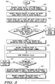
- FIG. 5 is a logic flow diagram of steps executed by a wireless BTS system or other system control device in accordance with one embodiment of the present invention.
- the logic flow begins (501) when the system control device allocates a rescue channel for use in transmitting information packets that have not been successfully received by one or more of the other wireless devices in the network.
- the system control device determines (503) respective signal quality levels for channels that are available for use as rescue channels.
- Such channels may be channels dedicated for use as rescue channels or channels assigned primarily for other uses, such as for supporting the transmission of non-real-time information packets (e.g., packet data), and only secondarily functioning as rescue channels.
- the system control device instructs (505) the other wireless devices in the network to also measure the signal quality levels of all candidate rescue channels (e.g., as identified by channel identifiers transmitted along with a measurement instruction communicated over a broadcast control channel) and report such signal quality information to the system control device over a reverse control channel.
- the wireless network utilizes time division duplex channels; thus, the broadcast control channel and the reverse control channel are different sets of time slots in each time division multiplexed time frame as illustrated in FIG. 4 .
- the signal quality levels are preferably received signal strength indication (RSSI) measurements indicating the levels of interference present on the measured channels, although other conventional signal quality metrics may be used.
- RSSI received signal strength indication
- the control device selects (507) the rescue channel based on its own measured signal quality levels and the signal quality levels reported by the other wireless devices. For example, the system control device may select the rescue channel as the candidate rescue channel that exhibits the best downlink signal quality (as measured by the wireless devices other than the system control device) and the best uplink signal quality (as measured by the system control device). If such a candidate rescue channel does not exist, then a weighting may be applied to the signal quality measurements to determine the selected rescue channel (e.g., the downlink signal quality measurements may be given a higher weighting than the uplink measurements).
- the rescue channel is preferably selected to have a carrier frequency that is different than the carrier frequencies of the primary channels used to convey real-time information in order to reduce the likelihood that the rescue channel is being subject to the same levels and type of interference as those that resulted in corruption of a transmitted packet to the extent that a retransmission was required.
- the identity of the rescue channel is transmitted over the broadcast control channel.
- the selection of the rescue channel preferably occurs before any information packets (or at least any real-time information packets) are conveyed to the wireless devices in order to establish a channel arrangement that facilitates reliable communications with minimal delay.
- the rescue channel identification may be periodically transmitted to the wireless devices over the broadcast control channel to insure that each wireless device, as it is powered up and registers in the system, is informed of which channel to switch to for retransmissions of corrupted information packets.
- the rescue channel may be selected on a communication-by-communication basis just prior to assignment of a primary channel for transmission of information packets to a target wireless device. That is, when information is received by the system control device that is intended for one of the target devices, the system control device retrieves previously stored signal quality information for the candidate rescue channels and then selects the best rescue channel based on the stored data. The system control device then communicates the selection of the rescue channel to the target device at substantially the same time as the system control device informs the target device of the primary channel assignment.
- Such an embodiment provides greater flexibility for proper selection of the rescue channel on a just-in-time basis, increasing the likelihood that the rescue channel selected for a particular communication will be the best one available.
- the system control device After the rescue channel is originally established, the system control device performs regular (e.g., periodic or as often as reasonable given the particular loading of the network) determinations (509) of the signal qualities of the current rescue channel and of the other candidate rescue channels in an attempt to maintain, on a substantially continuous basis, the highest quality rescue channel for use in retransmitting unsuccessfully received information packets. To effectuate these determinations, the system control device regularly measures the uplink signal qualities of the current rescue channel and the other candidate rescue channels (e.g., channels being utilized primarily for the transmission of non-real-time information) and regularly instructs the other wireless devices in the network (or at least those devices that are targets for the transmission of real-time information) to measure the downlink signal qualities of such channels.
- regular e.g., periodic or as often as reasonable given the particular loading of the network
- the system control device and the other wireless devices measure the current rescue channel and the other candidate rescue channels during time slots that are not being used by the particular devices to transmit or received information packets.
- the transmissions on such channels are temporarily interrupted on a regular basis to enable the wireless devices to perform interference level and other signal quality measurements.
- the system control device determines (509) that the current rescue channel has an unacceptable signal quality (e.g., interference levels that exceed a threshold) or that the actual or expected signal quality level of another candidate rescue channel is better or more favorable than the actual or expected signal quality of the current rescue channel, the system control device selects (511) the higher quality rescue channel as the new rescue channel and informs the wireless devices, through a broadcast control channel message, of the new rescue channel selection.
- the system control device is regularly monitoring the quality level of the rescue channel to substantially increase the likelihood that retransmissions, if they need to occur, are communicated on a high quality channel.
- the system control device receives sufficient data to compute signal quality trends for the rescue channel and the rescue channel candidates. From these trends, the system control device can determine (e.g., using conventional extrapolation and statistical techniques) expected signal qualities for the rescue channel and the other rescue channel candidates. As noted above, the system control device may be programmed to select or re-select the rescue channel based on the expected or projected signal qualities of the current rescue channel and the other rescue channel candidates.
- steps 509 and 511 are depicted in FIG. 5 as occurring prior to assignment of a primary channel for transmitting information packets to a wireless device, one of ordinary skill in the art will readily recognize that such steps are preferably performed repeatedly throughout the operation of the network in order to maintain the selection of high quality rescue channels, and the particular location of steps 509 and 511 in FIG. 5 should not be interpreted to limit the timing of the performance of such steps in any way.
- the rescue channel is preferably originally established prior to the transmission of any real-time information packets to a particular target wireless device.
- the system control device After a rescue channel has been selected and the system control device receives information from an information source, such as a cable service provider or other information service provider, the system control device assigns (513) a primary or traffic channel for use in transmitting the information, preferably in the form of information packets, to the target wireless device, and informs (513) the target device of the primary channel assignment over the broadcast or some other control channel.
- the assigned primary channel comprises a TDD channel containing one or more time slots per time frame for transmitting the information packets to the target device and one time slot per time frame to enable the target device to acknowledge, positively or negatively, successful receipt of the transmitted packet.
- the preferred rescue channel is also a similarly arranged TDD channel operating on a carrier frequency different than the carrier frequency of the primary channel to mitigate the likelihood of being exposed to common interference as noted above.
- the rescue channel may be selected as a second time slot or set of time slots operating on the same carrier frequency as the primary channel, or the rescue channel may utilize a different multiple access scheme then the primary channel provided that the wireless device is capable of multi-mode operation.
- the system control device transmits (515) an information packet to the wireless device over the primary channel (e.g., in a time slot of a time frame in a TDMA network).
- the system control device also stores (517) the transmitted packet in memory in case retransmission is necessary.
- the system control device determines (519) whether the transmitted packet was received successfully by the target device. This determination is preferably performed by detecting an ACK or a NACK in the acknowledgment or reverse time slot of the assigned primary TDD channel.
- the system control device When the system control device determines (519) that the transmitted packet was received successfully, the system control device deletes (521) the stored packet from memory and transmits (515) the next packet to the target device over the assigned primary channel. However, when the system control device determines (519) that the transmitted packet was not received successfully, the system control device retrieves (523) the stored packet from memory and retransmits (523) the packet to the wireless device over the rescue channel. In addition, the system control device transmits (525) a subsequent information packet (e.g., the next or another applicable information packet of the information sequence) to the target wireless device over the primary channel. That is, the system control device preferably transmits a new information packet substantially contemporaneously with retransmission of the missed packet in order to minimize transmission delay.
- a subsequent information packet e.g., the next or another applicable information packet of the information sequence
- the missed information packet is transmitted in one time slot over the carrier frequency supporting the rescue channel during the same time frame that the new information packet is transmitted in a time slot over the carrier frequency supporting the primary channel.
- the retransmitted packet and the new packet are preferably received at the target device in the same TDMA time frame.
- the above rescue channel selection and retransmission procedures preferably continue throughout the duration of the information sequence transmission.
- FIG. 6 is a logic flow diagram 600 of steps executed by a wireless BTS system or other system control device in accordance with an alternative embodiment of the present invention.
- the logic flow begins (601) when the system control device establishes and maintains (603-611) a high quality rescue channel for use in retransmitting information packets that have not been successfully received by one or more of the other wireless devices in the network.
- the steps of the logic flow performed in blocks 603-611 are essentially the same as the steps described above with respect to blocks 503-511 of FIG. 5 , except that, in this embodiment, the rescue channels are limited to being channels that primarily support the transmission of non-real-time information (e.g., packet data).
- non-real-time information e.g., packet data
- the system control device temporarily and regularly interrupts the transmission of non-real-time information over the rescue channel. Without such scheduled interruptions, measurement of interference levels present on the particular rescue channel could prove to be very difficult, if not impossible.
- the wireless devices and the system control device determine the signal quality levels of the rescue channel. After making such determinations, the wireless devices transmit their respectively determined signal quality levels to the system control device.
- the received signal qualities are then used by the system control device, as discussed in detail above, to maintain selection of the current rescue channel, or to select a new rescue channel in the event that the one or more of the signal quality levels reported by the wireless devices or measured by the system control device indicates unacceptable signal quality of the current rescue channel.
- the system control device After a rescue channel has been selected and the system control device receives real-time information intended for a target wireless device in the network from an information source, the system control device assigns (613) a primary channel for use in transmitting the information packets to the target wireless device, and informs (613) the target device of the primary channel assignment over the broadcast or some other control channel.
- the assigned primary channel and the selected rescue channel preferably comprise TDD channels operating in a TDMA system on different carrier frequencies to mitigate the likelihood of common interference being present on both channels.
- the system control device assigns (613) the rescue channel for primary use in transmitting non-real-time information to one or more other wireless devices. That is, in this embodiment, the rescue channel for purposes of transmitting real-time information doubles as a primary channel for transmitting non-real-time information in order to more efficiently utilize wireless resources, as compared to maintaining dedicated rescue channels.
- the assignment of the rescue channel as a primary non-real-time information channel is communicated to the applicable wireless devices (which devices may also include the device targeted to receive real-time information) over the broadcast or some other control channel.
- the system control device transmits (615) an information packet to the wireless device over the primary channel.
- the system control device also stores (617) the transmitted packet in memory in case retransmission is necessary.
- the system control device also transmits (619) non-real-time information packets to wireless devices over the rescue channel in accordance with the rescue channel's primary use as a packet data or other non-real-time information channel.
- the system control device determines (621) whether the transmitted real-time information packet was received successfully by the target wireless device. This determination is preferably performed by detecting an ACK or a NACK in the acknowledgment or reverse time slot of the assigned primary TDD channel as discussed above.
- the system control device When the system control device determines (621) that the transmitted packet was received successfully, the system control device deletes (623) the stored packet from memory and transmits (615) the next real-time information packet to the target device over the assigned primary channel. On the other hand, when the system control device determines (621) that the transmitted packet was not received successfully, the system control device temporarily interrupts (625) transmissions of non-real-time information packets over the rescue channel, retrieves the stored real-time information packet from memory, and retransmits (627) the retrieved packet to the wireless device over the rescue channel.
- the system control device transmits (629) a subsequent real-time information packet (e.g., the next or another applicable information packet of the information sequence) to the target wireless device over the primary channel.
- a subsequent real-time information packet e.g., the next or another applicable information packet of the information sequence
- substantially contemporaneous transmission of the next information packet over the primary channel is performed to minimize transmission delay and thereby maintain a quality of service typically expected of real-time information transmissions.
- the retransmitted information packet is transmitted in one time slot over the carrier frequency supporting the rescue channel during the same time frame that the new information packet is transmitted in a time slot over the carrier frequency supporting the primary channel.
- the retransmitted packet and the new packet are preferably received at the target device in the same TDMA time frame.
- the rescue channel After the rescue channel is no longer needed for retransmitting corrupted real-time information packets, the rescue channel reverts to a primary channel for transmitting non-real-time information.
- the above rescue channel selection and usage procedures preferably continue throughout the duration of the real-time information sequence transmission.
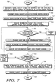
- FIG. 7 is logic flow diagram 700 of steps executed by a wireless electronic device in accordance with the present invention.
- the logic flow begins (701) when the wireless device, after receiving identifications of available rescue channels from the system control device, determines (703) signal quality levels for such channels as instructed by the system control device, and transmits (705) the signal quality levels to the system control device over a control channel. Some time after transmitting the signal quality levels, the wireless device receives (707) the identifications of the currently selected rescue channel and the currently assigned primary channel for purposes of an upcoming set of information packet transmissions from the system control device.
- the wireless device accesses the assigned primary channel and receives (709) an information packet from the system control device.
- the wireless device determines (711) whether the received packet was received successfully. In the preferred embodiment, such determination is made by measuring a bit or block error rate in accordance with known techniques to determine the recoverability of the information contained in the information packet. If the information packet was received successfully, the wireless device transmits (713) a positive acknowledgement message (ACK) back to the system control device to inform the system control device that the information packet was received successfully.
- ACK positive acknowledgement message
- the wireless device transmits (715) a negative acknowledgment message (NACK) or otherwise informs the system control device (e.g., by not transmitting any acknowledgment message) that the transmitted information packet was not received successfully.
- NACK negative acknowledgment message
- the primary channel is a time division duplex channel and the wireless device transmits the ACK or the NACK in a reverse time slot of the same time frame that includes the forward time slot that contained the information packet.
- the system control device transmits an information packet to the wireless device and is informed by the wireless device as to whether or not the transmitted packet was received successfully. Whether the information packet is received successfully or not, the wireless device preferably stores the information packet in a buffer memory to allow proper sequential processing of the information packets.
- the wireless device receives (717) the retransmitted information packet over the rescue channel.
- the wireless device also receives (719) a new information packet over the primary channel. Therefore, at least with respect to the transmission of real-time information packets, the retransmitted packet is transmitted substantially in parallel with a newly transmitted packet in order to minimize the delays typically associated with a reliable, retransmission protocol.
- the wireless device receives the retransmitted and newly transmitted information packets in different time slots of the same time frame to implement the substantially parallel communication of the retransmitted and newly transmitted information packets.
- the wireless device Upon receiving the retransmitted packet over the rescue channel, the wireless device determines (721) whether the retransmitted packet was received successfully. If the retransmitted packet was not received successfully, the wireless device transmits (723) a NACK back to the system control device and the logic flow continues at block 717.
- the wireless device might also store the corrupted, retransmitted information packet in the buffer memory (e.g., either replace the existing corrupted packet or selectively combine the corrupted, retransmitted packet with the corrupted original packet) if the wireless device is programmed to selectively combine retransmitted packets with originally, partially corrupted packets.
- the wireless device in accordance with its programming instructions, either combines (725) the retransmitted packet with the previously stored corrupted packet or replaces (725) the stored corrupted packet with the retransmitted packet to produce a corrected packet.
- the wireless device then processes (727) corrected packets and originally successfully received packets to reconstruct the sequence of information formed by the packets, and the logic flow ends (729).
- Each packet preferably includes a sequence identifier that enables the wireless device's processor to properly arrange the successfully received packets (whether originally transmitted or retransmitted) to form the original sequence of information.
- the logic flow depicted in FIG. 7 continues for the duration of each information sequence (which sequence may last for hours (e.g., until the wireless device is turned off) in the event that the information sequence is television programming or public radio transmissions).
- the wireless device and the system control device determine the signal quality levels of the rescue channel on a regular basis.
- the wireless device transmits its determined signal quality level to the system control device for use in evaluating the condition of the currently selected rescue channel. If the system control device determines that, based on the signal quality levels reported by the wireless device or other wireless devices in the network and/or measured by the system control device, the current rescue channel has an unacceptable signal quality (e.g., measured or reported signal levels exceed a threshold) and needs to be changed, the wireless device receives a control channel message from the system control device indicating the identification of the newly selected rescue channel. As discussed in detail above, the newly selected rescue channel is chosen based on signal quality measurements of rescue channel candidates that were made by the wireless devices in the network and by the system control device.
- the present invention encompasses a method and apparatus for reliably communicating information packets in a wireless communication network.
- real-time information can be communicated reliably in a wireless network, while maintaining a quality of service typically expected by persons who are generally accustomed to using wired devices.
- the present invention makes efficient use of wireless resources to provide the foregoing reliability and quality of service benefits.
- the present invention insures that the highest quality available rescue channel is maintained to support real-time information packet retransmissions, thereby increasing the likelihood that a only a single retransmission is necessary to overcome transmission of an unrecoverable packet.
- the channel control functions performed by the BTS system controller 201 may be distributed among the wireless device processors 301 or be performed by a particular wireless device processor on a permanent or interim basis. Accordingly, the specification and drawings are to be regarded in an illustrative rather than a restrictive sense, and all such modifications are intended to be included within the scope of the present invention.
- the term "comprises,” “comprising,” or any other variation thereof is intended to refer to a non-exclusive inclusion, such that a process, method, article of manufacture, or apparatus that comprises a list of elements does not include only those elements in the list, but may include other elements not expressly listed or inherent to such process, method, article of manufacture, or apparatus.
Landscapes
- Engineering & Computer Science (AREA)
- Computer Networks & Wireless Communication (AREA)
- Signal Processing (AREA)
- Mobile Radio Communication Systems (AREA)
- Communication Control (AREA)
- Detection And Prevention Of Errors In Transmission (AREA)
- Small-Scale Networks (AREA)
Claims (13)
- Verfahren (500, 600) für eine erste drahtlose Vorrichtung zum zuverlässigen Kommunizieren von Informationspaketen zu einer zweiten drahtlosen Vorrichtung in einem drahtlosen Kommunikationsnetzwerk, das ein Mehrfachzugriffsprotokoll im Zeitmultiplex verwendet, bei dem Information in Zeitfenstern kommuniziert wird, die in Zeitframes angeordnet sind, wobei das Verfahren die folgenden Schritte umfasst:Übertragen (515, 615) eines ersten Informationspakets zu der zweiten drahtlosen Vorrichtung über einen ersten drahtlosen Kommunikationskanal, der wenigstens ein Zeitfenster eines ersten Zeitframes auf einer ersten Trägerfrequenz hat;Bestimmen (519, 621), ob das erste Informationspaket erfolgreich durch die zweite drahtlose Vorrichtung empfangen wurde;erneutes Übertragen (523, 627) des ersten Informationspakets zu der zweiten drahtlosen Vorrichtung über einen zweiten drahtlosen Kommunikationskanal, der wenigstens ein Zeitfenster auf einer zweiten Trägerfrequenz hat, in dem Fall, dass das erste Informationspaket nicht erfolgreich durch die zweite drahtlose Vorrichtung empfangen wurde; undÜbertragen (525, 629) wenigstens eines zweiten Informationspakets zu der zweiten drahtlosen Vorrichtung über den ersten drahtlosen Kommunikationskanal, wobei das erste Informationspaket und das zweite Informationspaket eine Sequenz von Information bilden, und wobei das zweite Informationspaket das nächste in der Sequenz ist,dadurch gekennzeichnet, dass der Schritt des Übertragens des zweiten Informationspakets die folgenden Schritte umfasst:
Übertragen des zweiten Informationspakets in wenigstens einem Zeitfenster über die erste Trägerfrequenz während eines zweiten Zeitframes, das dem ersten Zeitframe benachbart ist, wobei das zweite Zeitframe das gleiche Zeitframe ist, in dem das erste Informationspaket in wenigstens einem Zeitfenster über die zweite Trägerfrequenz erneut übertragen wird. - Verfahren nach Anspruch 1, ferner umfassend die folgenden Schritte:vor dem Schritt des Übertragens (515, 615) des ersten Informationspakets,Bestimmen (503, 603) von jeweiligen Signalqualitätspegeln für eine Mehrzahl von drahtlosen Kommunikationskanälen, die zur Verwendung in dem drahtlosen Kommunikationsnetzwerk verfügbar sind;Empfangen (507, 607) von Signalqualitätsinformation für die Mehrzahl von drahtlosen Kommunikationskanälen von der zweiten drahtlosen Vorrichtung; undAuswählen (509, 609) des zweiten drahtlosen Kommunikationskanals von der Mehrzahl von drahtlosen Kommunikationskanälen basierend auf den Signalqualitätspegeln und der empfangenen Signalqualitätsinformation.
- Verfahren nach Anspruch 1, wobei der erste drahtlose Kommunikationskanal und der zweite drahtlose Kommunikationskanal zwei von einer Mehrzahl von drahtlosen Kommunikationskanälen sind, die zur Verwendung in dem drahtlosen Kommunikationsnetzwerk verfügbar sind, wobei das Verfahren ferner die folgenden Schritte umfasst:Bestimmen (503, 603) eines Signalqualitätspegels des zweiten drahtlosen Kommunikationskanals;Empfangen (507, 607) von Signalqualitätsinformation mit Bezug zu dem zweiten drahtlosen Kommunikationskanal von der zweiten drahtlosen Vorrichtung; undAuswählen (511, 611) eines dritten drahtlosen Kommunikationskanals von der Mehrzahl von drahtlosen Kommunikationskanälen zum Zweck der erneuten Übertragung von erfolglos empfangenen Informationspaketen in dem Fall, dass der Signalqualitätspegel und/oder die Signalqualitätsinformation eine inakzeptable Signalqualität des zweiten drahtlosen Kommunikationskanals angibt.
- Verfahren nach Anspruch 3, wobei die Schritte des Bestimmens eines Signalqualitätspegels und des Empfangens von Signalqualitätsinformation auf einer regelmäßigen Basis durchgeführt werden, um eine Signalqualitätsbestimmung des zweiten drahtlosen Kommunikationskanals wenigstens während der Verwendung des zweiten drahtlosen Kommunikationskanals zum Zweck der erneuten Übertragung von erfolglos empfangenen Informationspaketen zu ermöglichen.
- Verfahren nach Anspruch 1, wobei das erste und das zweite Informationspaket Echtzeitinformation enthalten, die Audio und/oder Video enthält, wobei das Verfahren ferner Folgendes umfasst:Übertragen (619) von Nicht-Echtzeit-Informationspaketen über den zweiten drahtlosen Kommunikationskanal;wobei das erneute Übertragen (523, 627) des ersten Echtzeitinformationspaket Folgendes umfasst: in Anwort auf eine Bestimmung (621), dass das erste Echtzeitinformationspaket nicht erfolgreich empfangen wurde, vorübergehendes Unterbrechen (625) von Übertragungen von Nicht-Echtzeit-Informationspaketen über den zweiten drahtlosen Kommunikationskanal; und erneutes Übertragen (627) des ersten Echtzeitinfirmationspakets über den zweiten drahtlosen Kommunikationskanal.
- Verfahren (700) für eine erste drahtlose Vorrichtung zum zuverlässigen Empfangen von Informationspaketen von einer zweiten drahtlosen Vorrichtung in einem drahtlosen Kommunikationsnetzwerk, das ein Mehrfachzugriffsprotokoll im Zeitmultiplex verwendet, bei dem Information in Zeitfenstern kommuniziert wird, die in Zeitframes angeordnet sind, wobei das Verfahren die folgenden Schritte umfasst:Empfangen (709) eines ersten Informationspakets von der zweiten drahtlosen Vorrichtung über einen ersten drahtlosen Kommunikationskanal, der wenigstens ein Zeitfenster eines ersten Zeitframes auf einer ersten Trägerfrequenz hat;Informieren (711, 713, 715) der zweiten drahtlosen Vorrichtung darüber, ob das erste Informationspaket erfolgreich empfangen wurde;Empfangen (717) des ersten Informationspakets von der zweiten drahtlosen Vorrichtung über einen zweiten drahtlosen Kommunikationskanal, der wenigstens ein Zeitfenster auf einer zweiten Trägerfrequenz hat, in dem Fall, dass das erste Echtzeitinformationspaket zuvor nicht erfolgreich empfangen wurde; undEmpfangen (719) von wenigstens einem zweiten Informationspaket von der zweiten drahtlosen Vorrichtung über den ersten drahtlosen Kommunikationskanal, wobei das erste Informationspaket und das zweite Informationspaket eine Sequenz von Information bilden, und wobei das zweite Informationspaket das nächste in der Sequenz ist,dadurch gekennzeichnet, dass der Schritt des Empfangens des zweiten Informationspakets die folgenden Schritte umfasst:
Empfangen des zweiten Informationspakets in wenigstens einem Zeitfenster über die erste Trägerfrequenz während eines zweiten Zeitframes, das dem ersten Zeitframe benachbart ist, wobei das zweite Zeitframe das gleiche Zeitframe ist, in dem das erste Informationspaket in wenigstens einem Zeitfenster über die zweite Trägerfrequenz empfangen wird. - Verfahren nach Anspruch 6, ferner umfassend die folgenden Schritte:in dem Fall, dass das erste Informationspaket ursprünglich nicht erfolgreich auf dem ersten drahtlosen Kommunikationskanal empfangen wurde, Speichern (715) des ersten Informationspakets in einem Speicher bis zum Empfang des ersten Informationspakets über den zweiten drahtlosen Kommunikationskanal zum Produzieren eines gespeicherten Informationspakets;Kombinieren (725) des gespeicherten Informationspakets mit dem ersten Informationspaket, das auf dem zweiten drahtlosen Kommunikationskanal empfangen wurde, zum Produzieren eines korrigierten Informationspakets; undVerarbeiten (727) des korrigierten Informationspakets und des zweiten Informationspakets zum Wiederherstellen der Sequenz von Information.
- Verfahren nach Anspruch 6, ferner umfassend die folgenden Schritte:in dem Fall, dass das erste Informationspaket ursprünglich nicht erfolgreich auf dem ersten drahtlosen Kommunikationskanal empfangen wurde, Speichern (715) des ersten Informationspakets in einem Speicher bis zum Empfang des ersten Informationspakets über den zweiten drahtlosen Kommunikationskanal zum Produzieren eines gespeicherten Informationspakets;Ersetzen (725) des gespeicherten Informationspakets durch das erste Informationspaket, das über den zweiten drahtlosen Kommunikationskanal empfangen wurde, zum Produzieren eines korrigierten Informationspakets; undVerarbeiten (727) des korrigierten Informationspakets und des zweiten Informationspakets zum Wiederherstellen der Sequenz von Information.
- Verfahren nach Anspruch 6, wobei der Schritt des Informierens der zweiten drahtlosen Vorrichtung den folgenden Schritt umfasst:
Übertragen einer Bestätigungsnachricht zu der zweiten drahtlosen Vorrichtung in einem ersten Zeitfenster des ersten Zeitframes, wobei das erste Zeitfenster zeitlich später auftritt als ein zweites Zeitfenster des ersten Zeitframes, in dem das erste Informationspaket empfangen wurde, jedoch zeitlich früher als der Beginn des zweiten Zeitframes. - Drahtlose Basistransceiverstation (101) für ein drahtloses Kommunikationssystem, das ein Mehrfachzugriffsprotokoll im Zeitmultiplex verwendet, bei dem Information in Zeitfenstern kommuniziert wird, die in Zeitframes angeordnet sind, umfassend:einen Programmspeicher (209), der Betriebsinstruktionen zur Durchführung spezieller Funktionen speichert;einen Controller (201), der die in dem Programmspeicher gespeicherten Betriebsinstruktionen ausführt, um wenigstens die folgenden Funktionen durchzuführen:Zuweisen von drahtlosen Kommunikationskanälen zur Unterstützung beim Kommunizieren von Informationspaketen zu drahtlosen elektronischen Vorrichtungen (103-107),Steuern der Übertragung der Informationspakete zu den drahtlosen elektronischen Vorrichtungen, undBestimmen, basierend auf empfangener Information und/oder einem Mangel an empfangener Information von einer ersten drahtlosen elektronischen Vorrichtung, ob ein erstes Informationspaket, das zu der ersten drahtlosen elektronischen Vorrichtung übertragen wurde, erfolgreich durch die erste drahtlose elektronische Vorrichtung empfangen wurde;einen Transmitter (203), der auf den Controller (201) reagiert, der das erste Informationspaket zu der ersten drahtlosen elektronischen Vorrichtung über einen ersten drahtlosen Kommunikationskanal üebrträgt, der wenigstens ein Zeitfenster eines ersten Zeitframes auf einer ersten Trägerfrequenz ist, das erste Informationpaket erneut zu der ersten drahtlosen elektronischen Vorrichtung über einen zweiten drahtlosen Kommunikationskanal überträgt, der wenigstens ein Zeitfenster auf einer zweiten Trägerfrequenz ist, in dem Fall, dass das erste Informationspaket nicht erfolgreich durch die erste drahtlose elektronische Vorrichtung empfangen wurde, und wenigstens ein zweites Informationspaket zu der ersten drahtlosen elektronischen Vorrichtung über den ersten drahtlosen Kommunikationskanal überträgt, wobei das erste Informationspaket und das zweite Informationspaket eine Sequenz von Information bilden, und wobei das zweite Informationspaket das nächste in der Sequenz ist, und wobei der Transmitter (203) dazu konfiguriert ist, das zweite Informationspaket in wenigstens einem Zeitfenster über die erste Trägerfrequenz während eines zweiten Zeitframes zu übertragen, das dem ersten Zeitframe benachbart ist, wobei das zweite Zeitframe das gleiche Zeitframe ist, in dem das erste Informationspaket in wenigstens einem Zeitfenster über die zweite Trägerfrequenz erneut übertragen wird; undeinen Empfänger (205), der betriebsmäßig mit dem Controller (201) gekoppelt ist, der Information von den drahtlosen elektronischen Vorrichtungen empfängt.
- Drahtlose Basistransceiverstation nach Anspruch 10, wobei das erste und das zweite Informationspaket Echtzeitinformation enthalten, die Audio und/oder Video enthält, wobei der Transmitter (203) ferner zu Folgendem konfiguriert ist: Übertragen von Nicht-Echtzeit-Informationspaketen über den zweiten drahtlosen Kommunikationskanal; in Antwort auf eine Bestimmung, dass das erste Echtzeitinformationspaket nicht erfolgreich empfangen wurde, vorübergehendes Unterbrechen von Übertragungen von Nicht-Echtzeit-Informationspaketen über den zweiten drahtlosen Kommunikationskanal und erneutes Übertragen des ersten Echtzeitinformationspakets über den zweiten drahtlosen Kommunikationskanal.
- Drahtlose Vorrichtung (103-107) für ein drahtloses Kommunikationsnetzwerk (100), das ein Mehrfachzugriffsprotokoll im Zeitmultiplex verwendet, bei dem Information in Zeitfenstern kommuniziert wird, die in Zeitframes angeordnet sind, umfassend:einen Empfänger (305), der eine anfängliche Übertragung eines ersten Informationspakets von einer zweiten drahtlosen Vorrichtung (101) über einen ersten drahtlosen Kommunikationskanal empfängt, der wenigstens ein Zeitfenster eines ersten Zeitframes auf einer ersten Trägerfrequenz ist, eine erneute Übertragung des ersten Informationspakets über einen zweiten drahtlosen Kommunikationskanal empfängt, der wenigstens ein Zeitfenster auf einer zweiten Trägerfrequenz ist, in dem Fall, dass die anfängliche Übertragung des ersten Informationspakets nicht akzeptabel war, und wenigstens ein zweites Informationspaket von der zweiten drahtlosen Vorrichtung über den ersten drahtlosen Kommunikationskanal empfängt, wobei das erste Informationspaket und das zweite Informationspaket eine Sequenz von Information bilden, wobei das zweite Informationspaket das nächste in der Sequenz ist, wobei der Empfänger (305) dazu konfiguriert ist, das zweite Informationspaket in wenigstens einem Zeitfenster über die erste Trägerfrequenz während eines zweiten Zeitframes zu empfangen, das dem ersten Zeitframe benachbart ist, wobei das zweite Zeitframe das gleiche Zeitframe ist, in dem das erste Informationspaket in wenigstens einem Zeitfenster über die zweite Trägerfrequenz empfangen wird;einen Programmspeicher (309), der Betriebsinstruktionen zur Durchführung spezieller Funktionen speichert;einen Prozessor (301), der betriebsmäßig mit dem Empfänger (305) und dem Programmspeicher (309) gekoppelt ist, der die in dem Programmspeicher gespeicherten Betriebsinstruktionen ausführt, um wenigstens die folgenden Funktionen durchzuführen:Bestimmen, ob die anfängliche Übertragung des ersten Informationspakets, das von der zweiten drahtlosen Vorrichtung empfangen wurde, akzeptabel ist;Informieren der zweiten drahtlosen Vorrichtung darüber, ob die anfängliche Übertragung des ersten Informationspakets akzeptabel ist; undVerarbeiten des ersten Informationspakets und des zweiten Informationspakets zum Wiederherstellen der Sequenz von Information beim erfolgreichen Empfang des ersten Informationspakets und des zweiten Informationspakets; undeinen Transmitter (303), der auf den Prozessor (301) reagiert, der Information zu der zweiten drahtlosen Vorrichtung (101) überträgt.
- Drahtlose Vorrichtung (103-107) nach Anspruch 12, wobei der Transmitter (303) dazu konfiguriert ist, in einem ersten Zeitfenster des ersten Zeitframes eine Bestätigungsnachricht zu übertragen, die angibt, dass die anfängliche Übertragung des ersten Informationspakets nicht akzeptabel war, wobei das erste Zeitfenster zeitlich später auftritt als ein zweites Zeitfenster des ersten Zeitframes, in dem die anfängliche Übertragung des ersten Informationspakets empfangen wurde, jedoch zeitlich früher als der Beginn des zweiten Zeitframes.
Applications Claiming Priority (3)
| Application Number | Priority Date | Filing Date | Title |
|---|---|---|---|
| US10/222,317 US6741554B2 (en) | 2002-08-16 | 2002-08-16 | Method and apparatus for reliably communicating information packets in a wireless communication network |
| US222317 | 2002-08-16 | ||
| PCT/US2003/024395 WO2004017545A1 (en) | 2002-08-16 | 2003-08-05 | Method and apparatus for reliably communicating information packets in a wireless communication network |
Publications (3)
| Publication Number | Publication Date |
|---|---|
| EP1540866A1 EP1540866A1 (de) | 2005-06-15 |
| EP1540866A4 EP1540866A4 (de) | 2010-06-09 |
| EP1540866B1 true EP1540866B1 (de) | 2019-03-06 |
Family
ID=31714931
Family Applications (1)
| Application Number | Title | Priority Date | Filing Date |
|---|---|---|---|
| EP03788321.2A Expired - Lifetime EP1540866B1 (de) | 2002-08-16 | 2003-08-05 | Verfahren und vorrichtung zum zuverlässigen übermitteln von informationspaketen in einem drahtlosen kommunikationsnetz |
Country Status (7)
| Country | Link |
|---|---|
| US (1) | US6741554B2 (de) |
| EP (1) | EP1540866B1 (de) |
| JP (1) | JP4256344B2 (de) |
| KR (2) | KR101033421B1 (de) |
| CN (1) | CN100588141C (de) |
| AU (1) | AU2003257171A1 (de) |
| WO (1) | WO2004017545A1 (de) |
Cited By (1)
| Publication number | Priority date | Publication date | Assignee | Title |
|---|---|---|---|---|
| EP4351151A4 (de) * | 2021-05-24 | 2025-03-05 | LG Electronics Inc. | A/v-empfangsvorrichtung und drahtloses anzeigesystem |
Families Citing this family (161)
| Publication number | Priority date | Publication date | Assignee | Title |
|---|---|---|---|---|
| US6963993B1 (en) * | 2000-09-28 | 2005-11-08 | The United States Of America As Represented By The Administrator Of The National Aeronautics And Space Administration | Fail-over file transfer process |
| US20050192018A1 (en) * | 2001-08-14 | 2005-09-01 | Kyung-Hun Jang | Wireless data communication apparatus and method capable of checking receipt and status |
| KR100460970B1 (ko) * | 2002-01-10 | 2004-12-09 | 삼성전자주식회사 | 데이터 송수신 시스템 및 방법 |
| US7184763B2 (en) * | 2002-01-22 | 2007-02-27 | Honeywell International, Inc. | VHF ground station selection algorithm |
| US20040018850A1 (en) * | 2002-07-23 | 2004-01-29 | Ntt Docomo, Inc. | Method of deciding transmit power level, wireless terminal, base station, and mobile communications system |
| JP2004128563A (ja) * | 2002-09-30 | 2004-04-22 | Toshiba Corp | 無線システム、無線基地局及び無線端末 |
| US7457319B2 (en) * | 2002-10-16 | 2008-11-25 | Qualcomm, Incorporated | Data partition method to maximize bluetooth baseband throughput |
| JP2006506846A (ja) | 2002-11-12 | 2006-02-23 | ゼテーラ・コーポレイシヨン | 改良型通信機能付き電気装置 |
| US7649880B2 (en) | 2002-11-12 | 2010-01-19 | Mark Adams | Systems and methods for deriving storage area commands |
| US8005918B2 (en) | 2002-11-12 | 2011-08-23 | Rateze Remote Mgmt. L.L.C. | Data storage devices having IP capable partitions |
| US7170890B2 (en) | 2002-12-16 | 2007-01-30 | Zetera Corporation | Electrical devices with improved communication |
| US7382749B2 (en) * | 2002-11-26 | 2008-06-03 | Sony Corporation | Systems, methods, and apparatus with a common wireless communications protocol |
| FR2848761B1 (fr) * | 2002-12-11 | 2005-05-06 | Eastman Kodak Co | Systeme et procede de distribution d'images |
| US20060198520A1 (en) * | 2002-12-20 | 2006-09-07 | Peter Courtney | Secure transmission of digital audio signals |
| US20040203383A1 (en) * | 2002-12-31 | 2004-10-14 | Kelton James Robert | System for providing data to multiple devices and method thereof |
| US20040160975A1 (en) * | 2003-01-21 | 2004-08-19 | Charles Frank | Multicast communication protocols, systems and methods |
| CN1762121B (zh) * | 2003-03-13 | 2010-09-08 | Nxp股份有限公司 | 数字电信的测试设备 |
| US7394761B2 (en) * | 2003-04-29 | 2008-07-01 | Avocent Huntsville Corporation | System and method for delivering messages using alternate modes of communication |
| US7013143B2 (en) * | 2003-04-30 | 2006-03-14 | Motorola, Inc. | HARQ ACK/NAK coding for a communication device during soft handoff |
| KR100506253B1 (ko) * | 2003-05-26 | 2005-08-10 | 재단법인서울대학교산학협력재단 | 데이터 통신 시스템에서 전송 지연을 최소화하기 위한장치 및 방법 |
| KR100542101B1 (ko) * | 2003-06-02 | 2006-01-11 | 삼성전자주식회사 | 전송 파워 제어 방법 및 이를 이용한 블루투스 장치 |
| DE10325298B4 (de) * | 2003-06-04 | 2007-07-05 | Siemens Ag | Verfahren und Vorrichtung zur Erfassung der Rauigkeit von Gefäßen |
| EP1489773A1 (de) * | 2003-06-16 | 2004-12-22 | Mitsubishi Electric Information Technology Centre Europe B.V. | Zeitsteuerung mit Stopp-und-Warten ARQ Verfahren |
| US7336683B1 (en) * | 2003-06-17 | 2008-02-26 | Conexant Systems, Inc. | Efficient communication system for reliable frame transmission over broad SNR ranges |
| DE10329878B4 (de) * | 2003-07-02 | 2005-05-25 | Siemens Ag | Verfahren zur Übertragung von Paketdaten in einem Funktelekommunikationssystem |
| JP4069034B2 (ja) * | 2003-07-31 | 2008-03-26 | 松下電器産業株式会社 | 無線送信装置、無線受信装置、無線通信システム、無線送信方法及び無線受信方法 |
| JP2007521766A (ja) * | 2003-11-07 | 2007-08-02 | シャープ株式会社 | 限定された明示的なメッセージ交換を用いたネットワークコーディネートシステムおよび方法 |
| US8213301B2 (en) * | 2003-11-07 | 2012-07-03 | Sharp Laboratories Of America, Inc. | Systems and methods for network channel characteristic measurement and network management |
| US7486616B2 (en) * | 2003-12-16 | 2009-02-03 | Intel Corporation | Preemptive dynamic frequency selection |
| TW200522598A (en) * | 2003-12-19 | 2005-07-01 | Iwics Inc | Data transport protocol for a multi-station network |
| ATE418822T1 (de) * | 2004-04-01 | 2009-01-15 | Panasonic Corp | Interferenzverminderung bei wiederholungsübertragungen im aufwärtskanal |
| JP2007536868A (ja) * | 2004-05-06 | 2007-12-13 | コーニンクレッカ フィリップス エレクトロニクス エヌ ヴィ | Arqを用いてデータ・パケットを通信する方法、システムおよび局 |
| JP4099592B2 (ja) * | 2004-06-10 | 2008-06-11 | ソニー株式会社 | 通信システム、送信装置および受信装置 |
| US7263335B2 (en) * | 2004-07-19 | 2007-08-28 | Purewave Networks, Inc. | Multi-connection, non-simultaneous frequency diversity in radio communication systems |
| EP1810541B1 (de) * | 2004-11-02 | 2014-04-16 | Apple Inc. | Systeme und verfahren zur verwendung mit orthogonal-frequenzmultiplex |
| KR100678147B1 (ko) * | 2005-01-05 | 2007-02-02 | 삼성전자주식회사 | 광대역 무선 접속 통신 시스템에서 arq 관련 타이머의제어 방법과 장치 및 그 시스템 |
| US8428042B1 (en) * | 2005-01-10 | 2013-04-23 | Zte (Usa) Inc. | Feedback mechanisms for multicast/broadcast service in wireless communication networks |
| US8804935B2 (en) * | 2005-02-03 | 2014-08-12 | Avaya Inc. | Call establishment based on presence |
| WO2006091809A2 (en) * | 2005-02-23 | 2006-08-31 | Nokia Corporation | Scheduling of acknowledgement in systems supporting frame aggregation |
| JP2006237780A (ja) * | 2005-02-23 | 2006-09-07 | Casio Hitachi Mobile Communications Co Ltd | 放送通信連携制御装置および放送通信連携制御方法 |
| US7702850B2 (en) | 2005-03-14 | 2010-04-20 | Thomas Earl Ludwig | Topology independent storage arrays and methods |
| US7236766B2 (en) * | 2005-03-31 | 2007-06-26 | Tylu Wireless Technologies, Inc. | Filtered wireless communications |
| US7248587B1 (en) | 2005-04-11 | 2007-07-24 | Azul Systems, Inc. | Error recovery of variable-length packets without sequence numbers or special symbols used for synchronizing transmit retry-buffer pointer |
| ATE489783T1 (de) * | 2005-05-11 | 2010-12-15 | Ericsson Telefon Ab L M | Mehrträger-scheduling |
| US7620981B2 (en) | 2005-05-26 | 2009-11-17 | Charles William Frank | Virtual devices and virtual bus tunnels, modules and methods |
| KR100735290B1 (ko) * | 2005-06-07 | 2007-07-03 | 삼성전자주식회사 | 휴대단말기의 화상통화모드에서 영상데이터 제어방법 |
| JP4731214B2 (ja) * | 2005-06-17 | 2011-07-20 | ソニー エリクソン モバイル コミュニケーションズ, エービー | 携帯端末装置、コンテンツ配信装置、コンテンツ配信システム、及び通信プログラム |
| US7995464B1 (en) * | 2005-06-27 | 2011-08-09 | At&T Intellectual Property Ii, L.P. | Method and apparatus for measuring quality of service levels |
| WO2007002772A1 (en) * | 2005-06-28 | 2007-01-04 | Worcester Polytechnic Institute | Apparatus and methods for addressable communication using voice-grade radios |
| US7747921B2 (en) * | 2005-08-05 | 2010-06-29 | Sony Corporation | Systems and methods for transmitting data over lossy networks |
| US8819092B2 (en) | 2005-08-16 | 2014-08-26 | Rateze Remote Mgmt. L.L.C. | Disaggregated resources and access methods |
| US7743214B2 (en) * | 2005-08-16 | 2010-06-22 | Mark Adams | Generating storage system commands |
| US9270532B2 (en) | 2005-10-06 | 2016-02-23 | Rateze Remote Mgmt. L.L.C. | Resource command messages and methods |
| WO2007046564A1 (en) * | 2005-10-20 | 2007-04-26 | Open Solution Co., Ltd. | Short-distance wireless data transmitting apparatus and method |
| TWI277325B (en) * | 2005-10-28 | 2007-03-21 | Ind Tech Res Inst | Packet transmitting method of wireless network |
| KR100751143B1 (ko) | 2005-11-28 | 2007-08-22 | 엘지전자 주식회사 | 무선 텔레비전 장치, 무선 텔레비전 시스템 및 그의제어방법 |
| JP4541293B2 (ja) * | 2005-12-14 | 2010-09-08 | 日本電信電話株式会社 | 無線パケット通信方法および無線パケット通信システム |
| JP4788596B2 (ja) * | 2005-12-27 | 2011-10-05 | パナソニック株式会社 | 認証システム |
| EP1980066B1 (de) * | 2006-01-11 | 2019-05-29 | Fisher-Rosemount Systems, Inc. | Steuersystem mit übersetzung der drahtlosen adressendomäne in die einsatzorteinrichtungsadressendomäne |
| US20070174887A1 (en) * | 2006-01-23 | 2007-07-26 | Lehong Hu | Interactive mobile wireless digital TV |
| US8179855B2 (en) * | 2006-02-07 | 2012-05-15 | Research In Motion Limited | Method, and associated apparatus, for communicating data at reduced transmission latency in radio communication system having slotted interface |
| US7924881B2 (en) | 2006-04-10 | 2011-04-12 | Rateze Remote Mgmt. L.L.C. | Datagram identifier management |
| US7697441B2 (en) * | 2006-04-27 | 2010-04-13 | Microsoft Corporation | Computer system with black hole management |
| BRPI0711181A2 (pt) * | 2006-05-01 | 2011-08-23 | Ntt Docomo Inc | estação móvel, estação de base, e método de controle de comunicação |
| JP4845612B2 (ja) * | 2006-07-03 | 2011-12-28 | 株式会社ソニー・コンピュータエンタテインメント | 通信装置、通信中継装置およびゲーム装置 |
| EP1879410A1 (de) * | 2006-07-11 | 2008-01-16 | British Telecommunications Public Limited Company | Kanalauswahl in einem drahtlosen Ad-hoc-Netwerk |
| US8054784B2 (en) * | 2006-08-16 | 2011-11-08 | Tropos Networks, Inc. | Wireless mesh network channel selection |
| US20100272885A1 (en) * | 2006-08-16 | 2010-10-28 | SeekTech, Inc., a California corporation | Marking Paint Applicator for Portable Locator |
| US9167423B2 (en) * | 2006-09-29 | 2015-10-20 | Rosemount Inc. | Wireless handheld configuration device for a securable wireless self-organizing mesh network |
| US7920524B2 (en) * | 2006-09-29 | 2011-04-05 | Vixs Systems, Inc. | Multimedia server with channel control module and methods for use therewith |
| US8005020B2 (en) * | 2006-09-29 | 2011-08-23 | Rosemount Inc. | Wireless mesh network with multisized timeslots for TDMA communication |
| JP4848949B2 (ja) * | 2006-12-19 | 2011-12-28 | パナソニック株式会社 | 認証装置、認証方法及びプログラム |
| US8144846B2 (en) * | 2007-01-08 | 2012-03-27 | Motorola Solutions, Inc. | System and method for interrupting a transmitting communication unit in a communication system |
| US8625652B2 (en) * | 2007-01-11 | 2014-01-07 | Qualcomm Incorporated | Collision-free group hopping in a wireless communication system |
| US7873010B2 (en) * | 2007-03-07 | 2011-01-18 | Motorola Mobility, Inc. | Control signaling resource assignment in wireless communication networks |
| DE102007012832B4 (de) * | 2007-03-17 | 2012-08-23 | Thales Defence Deutschland Gmbh | Datenübertragungseinrichtung und Betriebsverfahren hierfür |
| US8379609B2 (en) * | 2007-03-29 | 2013-02-19 | Vixs Systems, Inc. | Multimedia client/server system with adjustable data link rate and range and methods for use therewith |
| GB2449230B (en) | 2007-04-24 | 2009-09-02 | Multitone Electronics Plc | Telecommunications system and method |
| US7984177B2 (en) * | 2007-04-30 | 2011-07-19 | Vixs Systems, Inc. | Multimedia client/server system with adjustable packet size and methods for use therewith |
| US8036702B2 (en) * | 2007-05-14 | 2011-10-11 | Intel Corporation | Method and apparatus for multicarrier communication in wireless systems |
| US8270436B2 (en) * | 2007-09-18 | 2012-09-18 | Telefonaktiebolaget Lm Ericsson (Publ) | Data structure boundary synchronization between a transmitter and receiver |
| KR20090030562A (ko) * | 2007-09-20 | 2009-03-25 | 엘지전자 주식회사 | 광대역 무선 접속 시스템에서 자원할당을 위한 패킷전송방법 |
| KR100821501B1 (ko) * | 2007-10-17 | 2008-04-14 | 김영언 | 근거리용 양방향 브로드캐스팅시스템 |
| US9072093B2 (en) * | 2007-12-19 | 2015-06-30 | Qualcomm Incorporated | Flexible control channels for unplanned wireless networks |
| US8276034B2 (en) * | 2007-12-27 | 2012-09-25 | Ricoh Company, Limited | Information processing apparatus, information processing method, and computer program product |
| US8015451B2 (en) * | 2008-01-24 | 2011-09-06 | International Business Machines Corporation | Controlling an unreliable data transfer in a data channel |
| US8806037B1 (en) | 2008-02-29 | 2014-08-12 | Netapp, Inc. | Remote support automation for a storage server |
| US20090219916A1 (en) * | 2008-02-29 | 2009-09-03 | Motorola, Inc. | Method to scan for critical transmissions while transmitting on a conventional time division multiple access channel |
| KR101482136B1 (ko) * | 2008-04-29 | 2015-01-14 | 엘지전자 주식회사 | 가전기기 및 가전기기 시스템 |
| KR101627219B1 (ko) * | 2008-04-29 | 2016-06-03 | 엘지전자 주식회사 | 가전기기 및 가전기기를 포함하는 가전기기시스템 |
| US8532273B2 (en) * | 2008-04-29 | 2013-09-10 | Lg Electronics Inc. | Home appliance and home appliance system |
| US20100040213A1 (en) * | 2008-04-30 | 2010-02-18 | Lg Electronics Inc. | Home appliance and home appliance system |
| US7913115B1 (en) * | 2008-04-30 | 2011-03-22 | Netapp, Inc. | Core file transfer |
| KR101404104B1 (ko) * | 2008-04-30 | 2014-06-10 | 엘지전자 주식회사 | 가전기기 진단시스템 및 그 동작방법 |
| US20090275346A1 (en) * | 2008-05-02 | 2009-11-05 | International Business Machines Corporation | System and Method for Predictive Caching of Data for a Mobile Computing Device |
| US9054953B2 (en) * | 2008-06-16 | 2015-06-09 | Lg Electronics Inc. | Home appliance and home appliance system |
| US8239720B2 (en) * | 2008-06-19 | 2012-08-07 | Microsoft Corporation | Communication over plural channels with acknowledgment variability |
| US8379083B1 (en) * | 2008-07-17 | 2013-02-19 | Sprint Communications Company L.P. | Simultaneous viewing and reliable recording of multimedia content over a network |
| EP2151940A1 (de) * | 2008-08-05 | 2010-02-10 | Nokia Siemens Networks OY | Kommunikationsnetzwerkelement und Verfahren zur Datenübertragung |
| DE102008039584B3 (de) * | 2008-08-25 | 2010-04-15 | Siemens Programm- Und Systementwicklung Gmbh & Co. Kg | Verfahren und Einrichtung zur Auswahl von Satellitenkanälen |
| US20100066554A1 (en) * | 2008-09-02 | 2010-03-18 | Lg Electronics Inc. | Home appliance system |
| US9485649B2 (en) | 2008-09-25 | 2016-11-01 | Fisher-Rosemount Systems, Inc. | Wireless mesh network with pinch point and low battery alerts |
| US8086909B1 (en) | 2008-11-05 | 2011-12-27 | Network Appliance, Inc. | Automatic core file upload |
| EP2184950B1 (de) * | 2008-11-07 | 2012-02-29 | Siemens Aktiengesellschaft | Verfahren zur Datenübertragung in einem lokalen Netzwerk |
| KR101442115B1 (ko) * | 2009-04-10 | 2014-09-18 | 엘지전자 주식회사 | 가전기기 및 가전기기 시스템 |
| KR101555586B1 (ko) * | 2009-04-10 | 2015-09-24 | 엘지전자 주식회사 | 가전기기 |
| KR101421685B1 (ko) * | 2009-04-10 | 2014-08-13 | 엘지전자 주식회사 | 가전기기 진단시스템 및 그 진단방법 |
| KR101597523B1 (ko) * | 2009-04-10 | 2016-02-25 | 엘지전자 주식회사 | 가전기기 서비스 장치 및 그 제어방법 |
| US8565079B2 (en) * | 2009-04-10 | 2013-10-22 | Lg Electronics Inc. | Home appliance and home appliance system |
| KR101579481B1 (ko) * | 2009-04-10 | 2015-12-22 | 엘지전자 주식회사 | 가전기기 진단시스템 및 그 진단방법 |
| KR20100112948A (ko) * | 2009-04-10 | 2010-10-20 | 엘지전자 주식회사 | 가전기기 진단시스템 및 그 진단방법 |
| KR101164652B1 (ko) * | 2009-04-20 | 2012-07-11 | 한국전자통신연구원 | 무선 개인 영역 네트워크에서 서비스 품질 보장을 위한 실시간 무선 통신 방법 |
| AU2010269313B2 (en) | 2009-07-06 | 2015-01-22 | Lg Electronics Inc. | Home appliance diagnosis system, and method for operating same |
| KR101403000B1 (ko) | 2009-07-24 | 2014-06-17 | 엘지전자 주식회사 | 가전기기 및 그 신호출력방법 |
| KR20110010374A (ko) | 2009-07-24 | 2011-02-01 | 엘지전자 주식회사 | 가전기기 진단시스템 및 그 방법 |
| KR101472401B1 (ko) * | 2009-07-31 | 2014-12-12 | 엘지전자 주식회사 | 가전기기 진단시스템 및 그 진단방법 |
| KR101607891B1 (ko) * | 2009-07-31 | 2016-04-11 | 엘지전자 주식회사 | 가전기기 진단시스템 및 그 진단방법 |
| KR101482138B1 (ko) * | 2009-07-31 | 2015-01-13 | 엘지전자 주식회사 | 가전기기 진단시스템 및 그 진단방법 |
| KR101482137B1 (ko) * | 2009-07-31 | 2015-01-13 | 엘지전자 주식회사 | 가전기기 진단시스템 및 그 진단방법 |
| KR101472402B1 (ko) * | 2009-07-31 | 2014-12-12 | 엘지전자 주식회사 | 가전기기 진단시스템 및 그 진단방법 |
| KR20110013582A (ko) * | 2009-07-31 | 2011-02-10 | 엘지전자 주식회사 | 가전기기 진단시스템 및 그 진단방법 |
| KR101553843B1 (ko) * | 2009-07-31 | 2015-09-30 | 엘지전자 주식회사 | 가전기기 진단시스템 및 그 진단방법 |
| AU2010279835B2 (en) * | 2009-08-05 | 2014-08-28 | Lg Electronics Inc. | Home appliance and method for operating the same |
| KR101748605B1 (ko) | 2010-01-15 | 2017-06-20 | 엘지전자 주식회사 | 냉장고 및 냉장고 진단시스템 |
| US10645628B2 (en) * | 2010-03-04 | 2020-05-05 | Rosemount Inc. | Apparatus for interconnecting wireless networks separated by a barrier |
| DE102010010890B4 (de) * | 2010-03-10 | 2012-03-22 | Siemens Aktiengesellschaft | Verfahren zum Ersetzen einer bestehenden Leiteinrichtung in einem Automatisierungssystem durch eine neue Leiteinrichtung und dazu ausgebildetes Automatisierungssystem |
| EP2592786B1 (de) | 2010-07-06 | 2015-03-18 | LG Electronics Inc. | Diagnosesystem für haushaltsgeräte und diagnoseverfahren dafür |
| KR101859589B1 (ko) * | 2010-08-16 | 2018-06-28 | 삼성전자 주식회사 | 무선 통신 시스템에서 단말기 내에 복수 개의 이종 통신 모듈이 있을 경우 간섭을 회피하는 방법 및 장치 |
| CN101938750B (zh) * | 2010-09-09 | 2014-04-02 | 华为技术有限公司 | 移动台无线频率序号集合的转换方法和基站上层控制节点 |
| US8737244B2 (en) | 2010-11-29 | 2014-05-27 | Rosemount Inc. | Wireless sensor network access point and device RF spectrum analysis system and method |
| US9197380B2 (en) * | 2010-12-17 | 2015-11-24 | Cisco Technology, Inc. | Repeater nodes in shared media networks |
| US20130272192A1 (en) * | 2011-01-07 | 2013-10-17 | Mediatek Inc. | Apparatuses and Methods for Hybrid Automatic Repeat Request (HARQ) Buffering Optimization |
| US20130005372A1 (en) | 2011-06-29 | 2013-01-03 | Rosemount Inc. | Integral thermoelectric generator for wireless devices |
| JP2013031075A (ja) * | 2011-07-29 | 2013-02-07 | Toshiba Corp | 映像送出装置及び映像送出装置で使用される制御方法 |
| KR101416937B1 (ko) | 2011-08-02 | 2014-08-06 | 엘지전자 주식회사 | 가전기기, 가전기기 진단시스템 및 동작방법 |
| KR101252167B1 (ko) | 2011-08-18 | 2013-04-05 | 엘지전자 주식회사 | 가전기기 진단장치 및 그 진단방법 |
| US8949958B1 (en) * | 2011-08-25 | 2015-02-03 | Amazon Technologies, Inc. | Authentication using media fingerprinting |
| JP5923715B2 (ja) * | 2012-02-29 | 2016-05-25 | パナソニックIpマネジメント株式会社 | 計測情報収集システム、無線ノード、無線ノードの通信方法及びプログラム |
| WO2013152097A1 (en) * | 2012-04-03 | 2013-10-10 | Nevion Usa, Inc. | Signal protection |
| KR101942781B1 (ko) | 2012-07-03 | 2019-01-28 | 엘지전자 주식회사 | 가전기기 및 가전기기 진단을 위한 신호음 출력방법 |
| KR20140007178A (ko) | 2012-07-09 | 2014-01-17 | 엘지전자 주식회사 | 가전기기 및 그 시스템 |
| WO2014036059A1 (en) * | 2012-08-28 | 2014-03-06 | Interdigital Patent Holdings, Inc. | Dynamic point-to-point spectrum licensing |
| US9451624B2 (en) * | 2013-02-14 | 2016-09-20 | Qualcomm Incorporated | Receiver measurement assisted access point control |
| JP6016718B2 (ja) * | 2013-06-26 | 2016-10-26 | 三菱電機株式会社 | 映像送受信システム、送信装置、および、受信装置 |
| US10346389B2 (en) * | 2013-09-24 | 2019-07-09 | At&T Intellectual Property I, L.P. | Facilitating determination of reliability of crowd sourced information |
| US9491772B2 (en) * | 2013-12-19 | 2016-11-08 | Echostar Technologies L.L.C. | Methods and systems for placeshifting data with interference mitigation |
| EP3085116B1 (de) * | 2013-12-19 | 2021-05-05 | Telefonaktiebolaget LM Ericsson (publ) | Bewertung der auswirkung der interferenz auf ein kabel |
| US20150189536A1 (en) * | 2013-12-31 | 2015-07-02 | Cambridge Silicon Radio Limited | Method and apparatus for agile wireless network signal adaptation |
| CN105103491A (zh) * | 2014-01-23 | 2015-11-25 | 华为技术有限公司 | 数据传输方法和装置 |
| US9350770B2 (en) | 2014-05-30 | 2016-05-24 | Apple Inc. | Redundant transmission channels for real-time applications on mobile devices |
| EP3024156A1 (de) * | 2014-11-19 | 2016-05-25 | Motorola Solutions, Inc. | Verfahren, Vorrichtung und System zum Senden von Kurzdaten während eines aktiven TDMA-Anrufs |
| US9467255B2 (en) * | 2014-12-23 | 2016-10-11 | Ibiquity Digital Corporation | Systems and methods for digital radio broadcast with cross platform reception |
| US9763120B2 (en) * | 2014-12-24 | 2017-09-12 | EVA Automation, Inc. | Redundant links for reliable communication |
| CN108282671B (zh) * | 2015-02-13 | 2020-08-25 | 海信集团有限公司 | 一种流媒体数据传输方法 |
| CN110249700A (zh) * | 2017-02-08 | 2019-09-17 | 索尼移动通讯有限公司 | 媒体接入控制 |
| CN109672686B (zh) * | 2018-12-28 | 2021-12-03 | 广州市巨硅信息科技有限公司 | 语音数据传输方法及装置 |
| CN112333844B (zh) | 2019-08-05 | 2025-07-04 | 硅工厂股份有限公司 | 无线电池管理系统、用于无线通信的节点和数据发送方法 |
| EP4111703A1 (de) | 2020-02-24 | 2023-01-04 | Sonova AG | Systeme und verfahren zur multiprotokollarbitrierung für hörgeräte |
| WO2021171057A1 (en) | 2020-02-24 | 2021-09-02 | Sonova Ag | Systems and methods for selective storing of data included in a corrupted data packet |
| CN115361367B (zh) * | 2022-10-20 | 2023-02-07 | 湖南康通电子股份有限公司 | 一种用于应急广播的双通道广播系统 |
| US12536114B2 (en) * | 2023-08-02 | 2026-01-27 | Dell Products Lp | System and method for guarding bit data packet self-recovery with a data packet communication and polling system for wireless input/output (IO) devices |
Citations (1)
| Publication number | Priority date | Publication date | Assignee | Title |
|---|---|---|---|---|
| WO2001022747A1 (en) * | 1999-09-22 | 2001-03-29 | Motorola Inc. | Selecting channels for retransmission of data packets |
Family Cites Families (15)
| Publication number | Priority date | Publication date | Assignee | Title |
|---|---|---|---|---|
| SE460941B (sv) | 1988-04-26 | 1989-12-04 | Ericsson Telefon Ab L M | Foerfarande i ett cellindelat mobiltelefonsystem att reducera spaerr vid oeverflyttning av samtal |
| SE466279B (sv) * | 1988-10-17 | 1992-01-20 | Ericsson Telefon Ab L M | Radioenhet foer oeverfoering av samtalsinformation i ett mobiltelefonsystem med kort raeckvidd |
| US5546411A (en) * | 1995-02-28 | 1996-08-13 | Motorola, Inc. | Method and apparatus for adaptively selecting a communication strategy in a selective call radio communication system |
| JP3351653B2 (ja) * | 1995-03-30 | 2002-12-03 | 株式会社東芝 | 無線通信システムの再送制御方式および端末装置 |
| US5689439A (en) * | 1995-03-31 | 1997-11-18 | Lucent Technologies, Inc. | Switched antenna diversity transmission method and system |
| FI101332B1 (fi) * | 1995-12-18 | 1998-05-29 | Nokia Telecommunications Oy | Epäjatkuvalähetys monikanavaisessa suurinopeuksisessa datasiirrossa |
| EP0820167A3 (de) * | 1996-07-18 | 1998-07-22 | Matsushita Electric Industrial Co., Ltd. | Steuerungsverfahren für selektive Wiederholungsprotokolle |
| US5913167A (en) | 1997-02-28 | 1999-06-15 | Motorola, Inc. | Method for transferring a communication link in a wireless communication system |
| US6101168A (en) * | 1997-11-13 | 2000-08-08 | Qualcomm Inc. | Method and apparatus for time efficient retransmission using symbol accumulation |
| US6587441B1 (en) * | 1999-01-22 | 2003-07-01 | Technology Alternatives, Inc. | Method and apparatus for transportation of data over a managed wireless network using unique communication protocol |
| US6208620B1 (en) * | 1999-08-02 | 2001-03-27 | Nortel Networks Corporation | TCP-aware agent sublayer (TAS) for robust TCP over wireless |
| KR100516686B1 (ko) | 2000-07-08 | 2005-09-22 | 삼성전자주식회사 | 부호분할다중접속 이동통신시스템의 복합 재전송방법 |
| US6636488B1 (en) * | 2000-10-11 | 2003-10-21 | Aperto Networks, Inc. | Automatic retransmission and error recovery for packet oriented point-to-multipoint communication |
| US6842461B2 (en) * | 2002-03-08 | 2005-01-11 | Motorola, Inc. | Method and apparatus for data retransmission within a communication system |
| US20050134710A1 (en) * | 2003-12-18 | 2005-06-23 | Toshiaki Nomura | Imaging systems for use with patrol cars and patrol cars having such imaging systems |
-
2002
- 2002-08-16 US US10/222,317 patent/US6741554B2/en not_active Expired - Lifetime
-
2003
- 2003-08-05 WO PCT/US2003/024395 patent/WO2004017545A1/en not_active Ceased
- 2003-08-05 JP JP2004529243A patent/JP4256344B2/ja not_active Expired - Lifetime
- 2003-08-05 AU AU2003257171A patent/AU2003257171A1/en not_active Abandoned
- 2003-08-05 KR KR1020057002662A patent/KR101033421B1/ko not_active Expired - Lifetime
- 2003-08-05 EP EP03788321.2A patent/EP1540866B1/de not_active Expired - Lifetime
- 2003-08-05 CN CN03819476A patent/CN100588141C/zh not_active Expired - Lifetime
- 2003-08-05 KR KR1020117001576A patent/KR101121884B1/ko not_active Expired - Lifetime
Patent Citations (1)
| Publication number | Priority date | Publication date | Assignee | Title |
|---|---|---|---|---|
| WO2001022747A1 (en) * | 1999-09-22 | 2001-03-29 | Motorola Inc. | Selecting channels for retransmission of data packets |
Cited By (1)
| Publication number | Priority date | Publication date | Assignee | Title |
|---|---|---|---|---|
| EP4351151A4 (de) * | 2021-05-24 | 2025-03-05 | LG Electronics Inc. | A/v-empfangsvorrichtung und drahtloses anzeigesystem |
Also Published As
| Publication number | Publication date |
|---|---|
| WO2004017545A1 (en) | 2004-02-26 |
| KR20050032607A (ko) | 2005-04-07 |
| KR20110017459A (ko) | 2011-02-21 |
| EP1540866A1 (de) | 2005-06-15 |
| WO2004017545B1 (en) | 2004-05-21 |
| US20040032853A1 (en) | 2004-02-19 |
| CN1675865A (zh) | 2005-09-28 |
| AU2003257171A1 (en) | 2004-03-03 |
| CN100588141C (zh) | 2010-02-03 |
| US6741554B2 (en) | 2004-05-25 |
| JP2005536149A (ja) | 2005-11-24 |
| KR101121884B1 (ko) | 2012-03-20 |
| EP1540866A4 (de) | 2010-06-09 |
| KR101033421B1 (ko) | 2011-05-11 |
| JP4256344B2 (ja) | 2009-04-22 |
Similar Documents
| Publication | Publication Date | Title |
|---|---|---|
| EP1540866B1 (de) | Verfahren und vorrichtung zum zuverlässigen übermitteln von informationspaketen in einem drahtlosen kommunikationsnetz | |
| US7058035B2 (en) | Communication system employing multiple handoff criteria | |
| JP4409176B2 (ja) | スケジュールされた伝送のスケジュール変更 | |
| US8213354B2 (en) | Method for transmission of ACK/NACK for uplink enhancement in a TDD mobile communication system | |
| KR100945613B1 (ko) | 데이터 전달 방법 | |
| US7339949B2 (en) | ARQ transmission and reception methods and apparatus | |
| KR100925126B1 (ko) | 고속 레이트 패킷 데이터 전송에서 고속 폐쇄 루프 레이트적응을 위한 방법 및 장치 | |
| CN100566227C (zh) | 用于通信装置的确认/非确认确定可靠性的方法 | |
| US7088701B1 (en) | Method and apparatus for adaptive transmission control in a high data rate communication system | |
| US20080081651A1 (en) | Communication Control Method, Radio Communication System, Base Station, and Mobile Station | |
| US20030099211A1 (en) | Radio communication system | |
| JP2004297232A (ja) | 無線通信システム、基地局及びそれらに用いる無線リンク品質情報補正方法並びにそのプログラム | |
| JP2006515139A (ja) | アップリンク信号の検出改善とアップリンク信号の電力節減とを図るシステムおよび方法 | |
| JP2004135287A (ja) | 送信機と受信機の間の伝送チャネルの品質を報告する方法 | |
| EP1684455B1 (de) | Kommunikationsverfahren, endgerät und basisstation | |
| KR101107817B1 (ko) | 통신 방법 | |
| KR101086807B1 (ko) | 무선 통신 시스템에서 순방향 링크 mac 채널의 용량 증가 방법 | |
| US20080049667A1 (en) | System For Packet-Error Triggered Control Channel Transmissions | |
| EP1576837B1 (de) | Vorrichtung und verfahren zur ausführung automatischer wiederholungsanfragen in drahtlosen kommunikationssystemen mit mehrfachzugriff | |
| CN102882664B (zh) | 用于在无线通信系统中提供自主重传的方法和系统 |
Legal Events
| Date | Code | Title | Description |
|---|---|---|---|
| PUAI | Public reference made under article 153(3) epc to a published international application that has entered the european phase |
Free format text: ORIGINAL CODE: 0009012 |
|
| 17P | Request for examination filed |
Effective date: 20050310 |
|
| AK | Designated contracting states |
Kind code of ref document: A1 Designated state(s): AT BE BG CH CY CZ DE DK EE ES FI FR GB GR HU IE IT LI LU MC NL PT RO SE SI SK TR |
|
| AX | Request for extension of the european patent |
Extension state: AL LT LV MK |
|
| DAX | Request for extension of the european patent (deleted) | ||
| RBV | Designated contracting states (corrected) |
Designated state(s): DE FR GB |
|
| RIN1 | Information on inventor provided before grant (corrected) |
Inventor name: GORDAY, PAUL, E. Inventor name: SIMPSON, FLOYD, D. Inventor name: D'AMICO, THOMAS, VICTOR |
|
| A4 | Supplementary search report drawn up and despatched |
Effective date: 20100507 |
|
| RIC1 | Information provided on ipc code assigned before grant |
Ipc: H04L 1/18 20060101AFI20100430BHEP |
|
| 17Q | First examination report despatched |
Effective date: 20101012 |
|
| RAP1 | Party data changed (applicant data changed or rights of an application transferred) |
Owner name: MOTOROLA MOBILITY, INC. |
|
| RAP1 | Party data changed (applicant data changed or rights of an application transferred) |
Owner name: MOTOROLA MOBILITY LLC |
|
| RAP1 | Party data changed (applicant data changed or rights of an application transferred) |
Owner name: GOOGLE TECHNOLOGY HOLDINGS LLC |
|
| REG | Reference to a national code |
Ref country code: DE Ref legal event code: R079 Ref document number: 60351856 Country of ref document: DE Free format text: PREVIOUS MAIN CLASS: H04J0003240000 Ipc: H04L0001180000 |
|
| RIC1 | Information provided on ipc code assigned before grant |
Ipc: H04L 1/18 19680901AFI20181019BHEP Ipc: H04L 1/22 19800101ALI20181019BHEP Ipc: H04L 1/02 19680901ALI20181019BHEP |
|
| GRAP | Despatch of communication of intention to grant a patent |
Free format text: ORIGINAL CODE: EPIDOSNIGR1 |
|
| RIN1 | Information on inventor provided before grant (corrected) |
Inventor name: SIMPSON, FLOYD, D. Inventor name: GORDAY, PAUL, E. Inventor name: D'AMICO, THOMAS, VICTOR |
|
| INTG | Intention to grant announced |
Effective date: 20181203 |
|
| GRAS | Grant fee paid |
Free format text: ORIGINAL CODE: EPIDOSNIGR3 |
|
| GRAA | (expected) grant |
Free format text: ORIGINAL CODE: 0009210 |
|
| RIC1 | Information provided on ipc code assigned before grant |
Ipc: H04L 1/22 20060101ALI20181019BHEP Ipc: H04L 1/02 20060101ALI20181019BHEP Ipc: H04L 1/18 20060101AFI20181019BHEP |
|
| AK | Designated contracting states |
Kind code of ref document: B1 Designated state(s): DE FR GB |
|
| REG | Reference to a national code |
Ref country code: GB Ref legal event code: FG4D |
|
| REG | Reference to a national code |
Ref country code: DE Ref legal event code: R096 Ref document number: 60351856 Country of ref document: DE |
|
| REG | Reference to a national code |
Ref country code: DE Ref legal event code: R097 Ref document number: 60351856 Country of ref document: DE |
|
| PLBE | No opposition filed within time limit |
Free format text: ORIGINAL CODE: 0009261 |
|
| STAA | Information on the status of an ep patent application or granted ep patent |
Free format text: STATUS: NO OPPOSITION FILED WITHIN TIME LIMIT |
|
| 26N | No opposition filed |
Effective date: 20191209 |
|
| PGFP | Annual fee paid to national office [announced via postgrant information from national office to epo] |
Ref country code: GB Payment date: 20220829 Year of fee payment: 20 Ref country code: DE Payment date: 20220829 Year of fee payment: 20 |
|
| PGFP | Annual fee paid to national office [announced via postgrant information from national office to epo] |
Ref country code: FR Payment date: 20220825 Year of fee payment: 20 |
|
| P01 | Opt-out of the competence of the unified patent court (upc) registered |
Effective date: 20230511 |
|
| REG | Reference to a national code |
Ref country code: DE Ref legal event code: R071 Ref document number: 60351856 Country of ref document: DE |
|
| REG | Reference to a national code |
Ref country code: GB Ref legal event code: PE20 Expiry date: 20230804 |
|
| PG25 | Lapsed in a contracting state [announced via postgrant information from national office to epo] |
Ref country code: GB Free format text: LAPSE BECAUSE OF EXPIRATION OF PROTECTION Effective date: 20230804 |