EP1541110A2 - Modulare Befestigungsvorrichtung für Ausrüstungen an zahnärtzlichen Behandlungsstühlen - Google Patents
Modulare Befestigungsvorrichtung für Ausrüstungen an zahnärtzlichen Behandlungsstühlen Download PDFInfo
- Publication number
- EP1541110A2 EP1541110A2 EP04106297A EP04106297A EP1541110A2 EP 1541110 A2 EP1541110 A2 EP 1541110A2 EP 04106297 A EP04106297 A EP 04106297A EP 04106297 A EP04106297 A EP 04106297A EP 1541110 A2 EP1541110 A2 EP 1541110A2
- Authority
- EP
- European Patent Office
- Prior art keywords
- segment
- arm
- link arm
- arm assembly
- link
- Prior art date
- Legal status (The legal status is an assumption and is not a legal conclusion. Google has not performed a legal analysis and makes no representation as to the accuracy of the status listed.)
- Withdrawn
Links
Images




Classifications
-
- A—HUMAN NECESSITIES
- A61—MEDICAL OR VETERINARY SCIENCE; HYGIENE
- A61G—TRANSPORT, PERSONAL CONVEYANCES, OR ACCOMMODATION SPECIALLY ADAPTED FOR PATIENTS OR DISABLED PERSONS; OPERATING TABLES OR CHAIRS; CHAIRS FOR DENTISTRY; FUNERAL DEVICES
- A61G15/00—Operating chairs; Dental chairs; Accessories specially adapted therefor, e.g. work stands
- A61G15/14—Dental work stands; Accessories therefor
- A61G15/16—Storage, holding or carrying means for dental handpieces or the like
Definitions
- a chair system typically includes a chair that is adjustable in height and is shaped to support the patient's body, generally from the head to the lower legs.
- the chair can usually be reclined to position the patient, and particularly the patient's mouth, for convenience to the dentist and other attending personnel.
- various equipment used in dental procedures is positioned within reach of the attending personnel by movable support arms that are connected to the dental chair, usually near its base.
- Such equipment traditionally included tools and fluid systems for providing water, compressed air and vacuum.
- support arms have been connected at various points, including either side of the chair, the front of the chair or the rear of the chair.
- such equipment arms are attached to nearby walls and are not attached to the chair itself.
- Two-handed dentistry refers to practices involving a single practitioner (e.g., dentist, assistant or hygienist), whereas four-handed dentistry refers to practices in which two individuals work together.
- available dental chair systems have been optimized for either two-handed or four-handed dentistry, and could not easily be adapted to switch between the two modes conveniently, as may be required in a busy practice.
- Exemplary styles of two-handed and four-handed dentistry are depicted in the schematics of Figs. 14A-14F.
- Such equipment may include information displays (such as one or more computer monitors), controls, lights, cuspidors, amalgam collection units, as well as traditional dentistry tools such as drills and compressed air, water and vacuum tools.
- information displays such as one or more computer monitors
- controls such as one or more computer monitors
- lights such as one or more lights
- cuspidors such as one or more cuspidors
- amalgam collection units such as drills and compressed air, water and vacuum tools.
- the system has one or more support arms that allow users to easily reconfigure how dental equipment is supported and positioned to accommodate different practice styles and needs.
- a dental chair system includes a base with a height-adjustable support to which a portion of a dental chair may be coupled, a link arm, a primary support arm and a secondary support arm.
- the support has a rear side (at the "head" end of the chair) and a longitudinal axis, which is defined to be substantially parallel to the chair's axis.
- the link arm has distal and proximal ends, with the proximal end being pivotably connected to the support adjacent the rear side such that the link arm is pivotable to opposite sides of the longitudinal axis about a substantially vertical pivot axis.
- the primary support arm is pivotably connected to the distal end of the link arm for rotation relative to the link arm about a substantially vertical pivot axis.
- the secondary support arm is connected to the distal end of the link arm substantially along the vertical pivot axis.
- the primary and secondary support arms are adapted to support weight, e.g., equipment, and to be moved relative to each other and to the link arm.
- the secondary support arm can have an anti-interference feature to allow movement of the secondary support arm relative to the primary support arm to prevent interference between the support arms when the primary support arm is pivoted.
- the secondary support arm can have an auxiliary pivot connection with a substantially horizontal pivot axis about which the second support arm can be vertically pivoted.
- the secondary support arm may be adapted to support operator equipment, including conduits, which as used herein include fluid conduits (such as hoses, tubing and/or other structures for handling fluids) for water, compressed air, vacuum, etc., and/or electrical conduits (such as cables, wires or other electrical conductor via which power is supplied or electrical signals are communicated).
- conduits such as hoses, tubing and/or other structures for handling fluids
- electrical conduits such as cables, wires or other electrical conductor via which power is supplied or electrical signals are communicated.
- a manifold can be coupled to the link arm, e.g., adjacent its distal end.
- the manifold may be mounted to the link arm substantially along the vertical pivot axis. In other embodiments, the manifold is mounted at other suitable locations.
- the dental chair system can include a pivot bracket shaped to receive and pivotably support the proximal end of the link arm.
- the bracket can be mounted to the rear side of the support.
- the bracket is mounted in alignment with the longitudinal axis.
- the link arm may be swingable through an arc of at least 180°, allowing the link arm to be angled relative to the longitudinal axis on either side by at least about 90°. In other embodiments, the range of rotation may be less, e.g., an arc of about 140°.
- the primary support arm may have an upwardly extending mast, which can be positioned, e.g., adjacent its distal end.
- the mast may be used to support operator equipment.
- operator equipment may be pivotably mounted on the mast and selectively rotatable relative to the mast (e.g., for re-orientation of the equipment after the primary support arm is swung to an opposite side of the longitudinal axis).
- One such type of equipment that can be rotatably mounted to the mast is a cabinet.
- Other equipment, such as a cuspidor can be rotatably mounted to the cabinet, which can provide an increased degree of freedom of movement for increased flexibility and convenience.
- connection between the secondary arm and the link arm may be a fixed connection, a pivotable connection, or other suitable type of connection.
- the secondary support arm may be attached to an upper surface of the link arm and cantilevered above a plane of the primary support arm and the link arm.
- the secondary support arm may be pivotable in a horizontal plane above the link arm and the primary support arm.
- the secondary support arm may include at least a first segment having the auxiliary pivot connection and at least a second segment pivotably connected to the first segment for rotation in a generally horizontal plane.
- the secondary support arm may also include at least a third segment pivotably connected to the second segment for rotation in a generally vertical plane.
- the dental chair system may include a chair coupled to the support, and the pivot axis for the link arm may intersect a back portion of the chair when the chair is in the reclined position.
- At least one of the link arm, the primary arm and the secondary arm may have a substantially hollow construction or interior open areas through which conduits can be routed.
- a dental chair system includes a base with a height-adjustable support to which a dental chair may be coupled, an equipment arm pivotably coupled to the support and an auxiliary pivot connection.
- the equipment support arm comprises multiple segments joined to each other at pivotable connections.
- the auxiliary pivot connection has a substantially horizontal pivot axis.
- the auxiliary pivot connection joins two of the segments, including, relative to the support, a proximal segment and a distal segment.
- the auxiliary pivot connection prevents the distal portion from rotating in a vertical plane below horizontal and allows rotation above horizontal, e.g., the support arm contacts an object upon lowering of the base.
- the manifold may be positioned between the auxiliary pivot connection and the base.
- the support arm may include an elongate, generally lateral portion, extending between the seat base and an inner side of the auxiliary pivot connection.
- the support arm may have a second substantially vertical pivot axis positioned outward of the auxiliary pivot connection.
- an arm assembly to adapt a dental chair for right-side or left-side use includes a compensating arm segment pivotably connected to the rear side of the dental chair, a primary arm pivotably connected to the compensating arm at a primary pivot axis and a secondary arm connected to the compensating arm.
- the primary arm is positioned to pivot in a generally horizontal plane.
- the secondary arm has multiple segments and is vertically and horizontally movable relative to the compensating arm and the primary arm.
- the length of the compensating arm can be set to position the primary pivot axis at a sufficient distance from the support to permit movement of the primary and secondary arms without interference.
- an arm assembly for a dental chair includes a single pivot connection positioned adjacent the head-end and below the patient supporting portion of the dental chair with a pivotably supported link arm, and at least two equipment arms connected to the link arm at points substantially aligned in a vertical direction.
- an arm assembly for positioning equipment in a dental chair system includes a first element for pivotable attachment to a dental chair, a second element pivotably attached to an end of the first element at a substantially vertical first pivot axis, a third element attached to the first element substantially along the first pivot axis, and a fourth element attached to the third element at a substantially vertical second pivot axis that is horizontally spaced from the first pivot axis.
- an arm assembly for a dental chair includes a link arm for pivotable connection to the rear of the dental chair allowing rotation in a substantially horizontal plane and a support arm connected to the link arm.
- the support arm has multiple pivotably connected elongate segments capable of being positioned in space at a desired location and a structural element for preventing interference between the support arm and other structure adjacent the dental chair.
- a multi-segmented arm assembly for a dental chair includes a link arm segment for pivotable attachment to a rear of the dental chair, a first segment coupled to a distal end of the link arm segment, a second segment pivotably connected to a distal end of the first segment at a substantially vertical pivot axis, a third segment pivotably connected to a distal end of the second segment at a substantially horizontal pivot axis, and a terminal segment pivotably connected to a distal end of the third segment.
- the terminal segment can be pivotably connected at a substantially horizontal pivot axis.
- Segments of the secondary arm may have a parallelogram supporting structure that retains the segments in their respective positions.
- at least the third and/or fourth segments have such supporting structures.
- the arm assembly may also include a multi-function electronic control unit coupled to one of the segments, the control unit having wiring extending through at least one of the segments.
- the electronic control unit can be coupled to the terminal segment.
- the electronic control unit can be rotatably coupled to the terminal segment.
- the arm assembly may include at least one tool holder rotatably mounted to the terminal segment.
- At least one of the segments can be configured to have a predetermined normal range of rotation about its respective pivot axis and to permit over-rotation beyond the predetermined normal range without damage.
- a multi-segmented arm assembly for supporting equipment for use with patients is pivotably connected to a rear of the dental chair and includes at least five segments, each segment having at least one pivotable connection to at least one other segment, the segments and pivotable connections allowing the arm assembly to be raised, lowered and rotated to position a distal end of the arm end at desired positions relative to the rear of the dental chair.
- a representative embodiment of a dental chair system includes a dental chair 11 coupled to a base 12 by a support portion 14.
- the support portion 14 is selectively movable to allow at least the raising and lowering of the chair 11 relative to the base 12 for facilitating access to a patient.
- the chair 11 as shown in Figs. 1 and 2 is in a semi-upright position, with a back section or portion 13a extending uprightly relative to a seat portion 13b.
- the back portion 13a can be reclined and more closely aligned with the seat portion 13b to position the patient in a prone position, as shown schematically in the plan views of Figs. 14A-14F.
- "rear" is defined to be proximal to the end of the chair 11 designed to support the patient's head and torso, i.e., the "head" end of the chair.
- the rear side of the base 12/support 14/chair 11 includes the areas rearward of a middle lateral axis M, including the rear surfaces of the base 12 and areas adjacent where the support portion 14 and chair 11 are connected.
- the chair 11 has a longitudinal axis A, a portion of which is shown in Figs. 1 and 2 extending from the rear area.
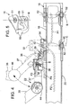
- a main pivot bracket 16 generally aligned with the axis A to which a compensating member, e.g., a link arm 18, is pivotably connected at its proximal end such that it can be pivoted from side-to-side in a generally horizontal plane (i.e., about a generally vertical pivot axis B, as shown in Figs. 3 and 4).
- a compensating member e.g., a link arm 18
- One or more equipment support arms such as, e.g., a primary arm 20 and a secondary arm 22 as shown, are attached to the link arm 18 adjacent its distal end.
- another arm for supporting a delivery system that houses a dentist's handpieces may be present, but this arm has been omitted from the figures for clarity.
- the pivot bracket 16 is attached to the support portion 14, so that the link arm 18 and the arms 20, 22 move with the chair 11, e.g., when it is raised and lowered.
- the pivot bracket 16 has a low-profile so that it does not unnecessarily impede access to the area beneath the chair 11, especially when the back portion 13a is reclined to the prone position.
- the primary arm 20 and the secondary arm 22 are configured for generally independent movement relative to each other.
- the primary arm 20 and the secondary arm 22 are connected to the link arm 18 along a common axis C.
- the axis C is the pivot axis for the primary support arm 20.
- the secondary arm 22 in Fig. 1 is configured to pivot in a horizontal plane about a different axis (i.e., an axis E as shown in Fig. 4) that is spaced farther than axis C from the axis B.
- the secondary arm 22 can also pivot about axis C.
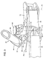
- Fig. 3 shows the pivot bracket 16, the link arm 18 and portions of the primary arm 20 and the secondary arm 22 in greater detail.
- the illustrated portion of the primary arm 20 is generally at the same vertical level as the link arm 18 and thus pivots in generally the same horizontal plane.
- the secondary arm 22 is attached at the upper surface of the link arm 18 and is cantilevered outwardly from its distal end.
- the secondary arm 22 is configured to rotate in a horizontal plane (about axis E) at a slightly higher level than the link arm 18 and the primary arm 20.
- Fig. 3 also shows a manifold 32 coupled to the upper surface of the link arm 18 adjacent its distal end.
- the manifold 32 can be pivotably connected to the link arm 18 to allow the manifold to be rotated relative to the link arm 18, e.g., during repositioning.
- the manifold 32 is generally aligned along the axis C and has a generally cylindrical or ellipsoidal shape.
- the manifold 32 serves to position conduits 34 extending from an area beneath the chair 11 and through the link arm 18 so that they drape effectively and do not interfere with movement of the arms 20, 22 and other equipment during procedures.
- the manifold 32 generally includes a screen (not shown) to prevent entry of foreign matter into fluid systems.
- conduits 34 are connected to various tools mounted to a tool holder 33 attached at a distal end of the secondary arm 22. These tools are used to provide water, to provide compressed air, and/or to provide vacuum.
- tools refers to tubing, cables, lines and other similar structure through which fluids, pressure, power or signals are transferred.
- various conduits may be routed through internal portions of the link arm 18, the primary arm 20 and the secondary arm 22.
- electrical, air and water lines may extend from beneath the chair and along the path P1 through the link 18, with the air and water lines being routed through the secondary arm 22 and exiting on its lower side (path P4), and the electrical line extending through the remaining portion of the secondary arm 22 (e.g., to provide power and/or communicate signals to equipment such as the tools and a control unit) (path P3).
- the path P2 represents a vacuum line extending from the area of the manifold 32 and through at least a portion of the primary support arm 20.
- conduit that extends from one of the tools 33 to the area below the chair that is not routed through or positioned by the manifold 32.
- the primary arm 20 and the secondary arm 22 are sized and shaped to movably support various equipment used in dental procedures.
- the arm 20 is referred to as the "primary" arm because it generally has a more substantial construction than the secondary arm 22, although this is not a requirement in all implementations.
- the primary arm 20 has an upwardly extending mast 24, which can be positioned as shown at its distal free end, or at other points along its length.
- a light standard 28 and a monitor 30 coupled to an upper end of the mast 24.
- the housing 23 can be rotatably coupled to the mast 24, such that equipment attached to the housing, e.g., a cuspidor 27 and/or an ancillary housing unit 26 (shown only in Fig. 2) can be rotated to any convenient orientation relative to the mast 24.
- equipment attached to the housing e.g., a cuspidor 27 and/or an ancillary housing unit 26 (shown only in Fig. 2) can be rotated to any convenient orientation relative to the mast 24.
- the housing 23 can be rotated to position the cuspidor 27 closer to the patient.
- the cuspidor 27 can also be independently rotatable relative to the housing 23.
- An interior space within the housing 23 can be used for various purposes, including housing circuitry and valves, as well as for storage of items.
- the ancillary housing 26 may be used for general storage, or may be equipped as an amalgam collection unit for storage of amalgam and other similar materials requiring special handling.
- the primary arm 20 is restricted to rotation in a generally horizontal plane about a first pivotable connection 35 at the axis C adjacent its proximal end.
- the connection with the mast 24 is a rigid one. It would be possible, of course, to adapt the primary arm 20 to include other segments allowing other motion, e.g., vertical movement to position equipment at different levels.
- the secondary arm 22 can have an anti-interference or clearance-providing feature that allows easy relative movement between the secondary arm 22 and the primary arm 20.
- the secondary arm 22 has an auxiliary pivot connection 31 between its proximal end attached at the axis C and a first pivot connection 36.
- the auxiliary pivot connection 31, which defines pivot axis D, permits the distally extending portion of the arm 22 to be pivoted upwardly in the vertical plane, e.g., as shown in Fig. 4.
- the auxiliary pivot connection 31 permits movement of the secondary arm 22 relative to other surrounding structure, e.g., to allow movement of the primary arm 20 and the secondary arm 22 relative to each other.
- the auxiliary pivot connection 31 will also permit pivoting in the event that the descending secondary arm 22 contacts another object upon the lowering of the chair 11, which may assist in preventing damage.
- the auxiliary pivot connection 31 may have an internal stop (not shown) to limit rotation of the distally extending portion of the arm 22 to a predetermined range.
- the secondary arm 22 has multiple segments.
- these segments include: (1) a short first segment 29, which includes the auxiliary pivot connection 31, connected to the link arm 18 at the axis C and having its distal end at the first pivot connection 36 (axis E); (2) a second segment 37 connected to the first segment 29 at the axis E and having its distal end at a second pivot connection 44; and (3) a third segment 38 connected to the second segment 37 and having its distal end at a third pivot connection 46.
- the third segment 38 is also connected to (4) an optional forth segment 40 with a fourth pivot connection 48 as shown in Figs. 1 and 2, to which another segment or equipment can be connected.
- the link arm 18 can also be properly considered as the "base" segment for the multi-segmented secondary arm.
- Fig. 12 shows an alternative embodiment of the secondary arm 22' having three segments, i.e., the segments 29, 37 and 40, without the segment 38.
- the shorter secondary arm 22' is referred to as the "short arm”
- the longer arm 22 is referred to as the "long arm.”
- a relatively short terminal segment 42 is pivotably attached to the segment 38 or the segment 40, respectively.
- the terminal segment 42 supports at least one tool holder 33 as shown in Figs. 1 and 2. If desired, the modular construction allows a second tool holder 33 to be added, as shown in Fig. 12. Each tool holder 33 is preferably rotatable relative to the terminal segment 42.
- a chair system control unit 43 which is sometimes referred to as a "touch pad.”
- the control unit is mounted above the tool holder(s) to allow easy access and viewing.
- the control unit 43 has a user interface with controls for allowing the practitioners to input commands, including, e.g., to reposition the chair (changing its height and/or inclination), to operate the light(s) and cuspidor, and to control various other subsystems.
- the control unit 43 is preferably rotatable relative to its mounting point so it can be oriented toward the user.
- the pivot connection 36 allows the secondary arm 22, 22' to be swung in a generally horizontal plane at a level above the link arm 18 and the primary arm 20.
- the pivot connections 44, 46 and 48 are designed to permit rotation of the respective segments in a generally vertical plane.
- Various combinations of vertical rotations among the segments permit the secondary arm 22, 22', and particularly any attached equipment such as the tool holder(s) 33 and the control unit 43, to be positioned as desired in space.
- the secondary arm 22, 22' can be raised, lowered and translated.
- connection between the first segment 29 and the link arm 18 at the axis C is typically configured as a rigid connection not allowing any rotation, but a non-rigid connection allowing at least some rotation could also be used.
- the dental chair system 10 may be configured as shown in Fig. 1 (primary arm 20 on the left side), Fig. 2 (primary arm 20 on the right side) or in any other different position within the range permitted by the link arm 18 and the primary arm 20.
- the link arm 18 is rotated to its full extent toward either the left side or the right side of the chair 11, i.e., to extend outward approximately perpendicular to the axis A. Rotations of the link arm 18 to other positions, are, of course, possible.
- Fig. 14C which is a schematic plan view
- the link arm is shown rotated to the left side of the chair with the primary arm 20 and attached equipment extending along the left side of the chair and positioned between the chair and the assistant.
- the secondary arm (“long arm”) is also positioned on the left side, but extends toward the head end of the chair.
- Positioning the link arm 18 to the left or the right of the longitudinal axis A repositions the vertical pivots for the primary arm 20 and secondary arm 22 or 22', respectively, thereby compensating for the position of the pivot bracket 16 and allowing the arms to be swung closer to the sides of the chair 11. Because the arms are positioned closer to the sides of the chair 11, they pose less interference to the practitioners. Because the link arm 18 is attached to the chair 11 along the longitudinal axis A, the dental chair system is not biased toward left-handed or right-handed dentistry and can be quickly adapted between both modes, even multiple times over each day as may be required in a busy practice.
- the primary arm 20 may be swung outward to provide the patient access to the floor to ease egress from and ingress into the chair.
- the secondary arm 22 or 22' may be initially configured as shown in Figs. 1 and 2, i.e., extending rearwardly, so as to be out of the way, e.g., during a patient's ingress into and egress from the chair. During treatment, the practioner(s) will position the secondary arm 22 or 22' as necessary to provide convenient access to the tools in the holder 33 and to avoid interference with other equipment.
- Figs. 14A-14F Exemplary positions for the secondary arm 22, 22' relative to the position of practitioner(s) for six different styles of dentistry practice are shown schematically in Figs. 14A-14F.
- the positions shown in Figs. 14A-14F are as would be used by typical right-handed dentists.
- the corresponding positions for left-handed dentists are not shown, but these positions would be the mirror images of Figs. 14A-14F relative to the longitudinal axis.
- Fig. 14A shows the long secondary arm, i.e., the secondary arm 22 with four segments, as it may be positioned for so-called "2-handed indirect" dental practice involving only a dentist.
- the dentist's typical practice area would be as shown in Fig. 14A (i.e., in the range from about 12 o'clock to about 8 o'clock).
- the long secondary arm 22 would be positioned as shown on the opposite side of the longitudinal axis relative to the dentist.
- Fig. 14B shows the short secondary arm, i.e., the secondary arm 22' with three segments, as it may be positioned for 2-handed indirect dental practice involving only a dentist. As indicated, the dentist's typical practice area would be as shown (i.e., in the range from about 12 o'clock to about 7 o'clock).
- Fig. 14C shows the long secondary arm, i.e., the secondary arm 22, as it may be positioned for "4-handed indirect" dental practice involving a dentist and another practitioner, referred to here as an assistant. As indicated, the dentist's typical practice area would be as shown (i.e., in the range from about 12 o'clock to about 8 o'clock). As described above, Fig. 14C also shows the relative position of the primary arm.
- Fig. 14D shows the short secondary arm, i.e., the secondary arm 22', as it may be positioned for "4-handed indirect" dental practice.
- the dentist's typical practice area would be as shown (i.e., in the range from about 12 o'clock to about 7 o'clock).
- Figs. 14E and 14F show the long secondary arm 22 and the short secondary arm 22', respectively, positioned for "2-handed direct" dental practice. As indicated, the dentist's typical practice area would be as shown (i.e., in the range from about 10 o'clock to about 7 o'clock).
- the primary arm 20 has a substantial lateral length between the axis C and its distal end adjacent to the mast 24, which can create a substantial moment from the weight of the arm and mast, the ancillary housing 26, the light 28 and monitor 30, etc., acting through this length.
- the link arm 18 and primary arm 20 each have a hollow cross-section to increase the resistance to bending and/or twisting in the link arm 18 and the primary arm 20, without unnecessarily increasing weight.
- the cross-section may have the shape of a sideways "D" with a broader, flat upper surface and a narrower, rounded lower surface.
- the hollow cross-section of the link arm 18 and the primary arm 20 allows the conduits 34 to be routed through the interior open areas as shown schematically in Fig. 4, which prevents the conduits 34 from tangling and provides for a more aesthetic appearance.
- the secondary arm 22 or 22' in the illustrated embodiment is configured to have segments that can be positioned individually at desired locations easily and which remain in place until repositioned again.
- the segments can be fitted with parallelogram structures that provide sufficient resistance to keep the segments in place when at rest, but the resistance can be overcome by a user to move the segments as desired.
- One or more of the segments, or attached equipment, such as the tool holder 33, may be configured to remain substantially level as the segments are repositioned. Such a configuration is shown for the segments in the exploded view of Fig. 13.
- Fig. 13 An exemplary construction is shown in Fig. 13 for the segment 40.
- a pair of rod halves 97, 98 is assembled together with a spring to maintain, under normal conditions, a longitudinal gap between respective lateral surfaces of the rod halves. If the segment 40 is rotated beyond its normal range of rotation, the rod halves 97, 98 can slide relative to each other until the lateral surfaces contact, thus providing a range of over-rotation without bending the rod halves 97, 98.
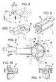
- Fig. 5 is a perspective view of the pivot bracket 16 of the illustrated embodiment.
- the pivot bracket 16 has mounting apertures 50 (two of which are shown in Fig. 5) and pivot apertures 51 for receiving a pivot member, such as pivot bolts 52 (Fig. 4) or a pivot pin.
- the pivot bracket 16 may be formed as a single piece as shown, or as multiple pieces.
- the pivot bracket 16 may also have a leveling feature 55 to assist in adjusting the inclination of the assembly.
- Fig. 6 is a perspective view of the link arm 18.
- the link arm 18 has a length of about 8 inches, which, when swung leftward or rightward of the longitudinal axis A, is sufficient in many applications for repositioning the arms 20, 22 along either side of the chair 11. Of course, other applications may require the link arm 18 to be resized to a different length.
- Figs. 7 and 8 are perspective views of a first part 54 and a second part 56, respectively, that are pivotably joined at the auxiliary pivot connection 31 of the first segment 29 (axis D).
- first part 54 is shown in dashed lines in relation to the second part in Fig. 8.
- the second part 56 has a projection 58 on its upper surface.
- Fig. 9 is a top plan view of the segment 37.
- the segment 37 is shown to have a range of rotation F relative to the second part 56 (shown in dashed lines) of about 200° as restricted by a groove 60 that receives the projection 58 as shown.
- Figs. 10 and 11 show cross-sections of the segment 37.
- the segment 37 has a generally elliptical hollow cross-section at points spaced from its ends.
- the other segments 38 and 40 of the secondary arm 22, 22' may have similar cross-sections.
- the pivot bracket 16, link arm 18 and the arms 20, 22, 22' can be made from any suitable materials.
- these components may be cast and then machined and/or subjected to a suitable surface treatment, as necessary.
- the various pivot connections may be made with bolts, such as the pivot bolts 52, pins, bearings, washers and/or other hardware suitable for providing secure but rotatable connections.
- the system is highly modular, as the configuration of the arms can be adapted to individual needs, e.g., through choice of the long secondary arm or the short secondary arm, the various items of equipment that can be supported by the primary arm, the number of tool holders, etc.
- the on-axis mounting configuration and rotatable equipment mounting allow for easy conversion between use by right-handed and left-handed practitioners, as well as between different styles of practice.
- the secondary arms afford a wide range of motion and have multiple degrees of freedom to provide more flexibility in positioning of equipment.
- the construction of the arms and other equipment is robust and has an aesthetic appearance.
Landscapes
- Health & Medical Sciences (AREA)
- Life Sciences & Earth Sciences (AREA)
- Animal Behavior & Ethology (AREA)
- General Health & Medical Sciences (AREA)
- Public Health (AREA)
- Veterinary Medicine (AREA)
- Accommodation For Nursing Or Treatment Tables (AREA)
- Dental Tools And Instruments Or Auxiliary Dental Instruments (AREA)
Applications Claiming Priority (2)
| Application Number | Priority Date | Filing Date | Title |
|---|---|---|---|
| US10/734,068 US7195219B2 (en) | 2003-12-10 | 2003-12-10 | Modular dental chair equipment mounting system |
| US734068 | 2003-12-10 |
Publications (2)
| Publication Number | Publication Date |
|---|---|
| EP1541110A2 true EP1541110A2 (de) | 2005-06-15 |
| EP1541110A3 EP1541110A3 (de) | 2005-07-27 |
Family
ID=34523080
Family Applications (1)
| Application Number | Title | Priority Date | Filing Date |
|---|---|---|---|
| EP04106297A Withdrawn EP1541110A3 (de) | 2003-12-10 | 2004-12-03 | Modulare Befestigungsvorrichtung für Ausrüstungen an zahnärtzlichen Behandlungsstuhlen |
Country Status (4)
| Country | Link |
|---|---|
| US (1) | US7195219B2 (de) |
| EP (1) | EP1541110A3 (de) |
| JP (1) | JP2005169093A (de) |
| AU (1) | AU2004226919A1 (de) |
Cited By (5)
| Publication number | Priority date | Publication date | Assignee | Title |
|---|---|---|---|---|
| WO2008061979A1 (en) | 2006-11-21 | 2008-05-29 | Planmeca Oy | Integrated dental care apparatus |
| US10188868B2 (en) | 2013-11-29 | 2019-01-29 | Nexstim Oyj | Device support apparatus |
| WO2020214731A1 (en) | 2019-04-16 | 2020-10-22 | A-Dec, Inc. | Tandem pivot mount for dental patient chair |
| IT202000000271A1 (it) | 2020-01-10 | 2021-07-10 | Cefla Soc Cooperativa | Riunito odontoiatrico ambidestro |
| US20220160481A1 (en) * | 2019-03-01 | 2022-05-26 | Ferton Holding S.A. | Instrument Support for a Treatment Device and Treatment Device Comprising Said Instrument Support |
Families Citing this family (38)
| Publication number | Priority date | Publication date | Assignee | Title |
|---|---|---|---|---|
| WO2004045341A1 (en) * | 2002-11-15 | 2004-06-03 | P--Ce Computers Inc. | Peripheral support apparatus and method |
| US7290836B2 (en) * | 2003-08-28 | 2007-11-06 | A-Dec, Inc. | Patient chair |
| DE112004003014T5 (de) * | 2004-11-15 | 2008-01-03 | Kabushiki Kaisha Morita Tokyo Seisakusho | Optische Zahndiagnosevorrichtung |
| JP2009507660A (ja) * | 2005-09-09 | 2009-02-26 | イノプラ インコーポレーテッド | 対象物洗浄装置を利用して対象物を研磨するための装置及び方法 |
| WO2007077548A1 (en) * | 2006-01-03 | 2007-07-12 | Ema Innovation Llc | Computer display viewing support |
| US7637572B1 (en) | 2006-07-10 | 2009-12-29 | Salvatore Cirami | Compactly foldable skywatcher's tripod |
| US20080016624A1 (en) * | 2006-07-21 | 2008-01-24 | Kathy Osborn | Soothing devices |
| US20080020672A1 (en) * | 2006-07-21 | 2008-01-24 | Kathy Osborn | Programmable baby mobiles and baby soothing devices |
| US20080164737A1 (en) * | 2007-01-08 | 2008-07-10 | Parafincorporation | Workstation with computer systems and components |
| US20090166306A1 (en) * | 2007-12-31 | 2009-07-02 | Ahearn David J | Delivery channel |
| FI123978B (fi) * | 2008-06-27 | 2014-01-15 | Planmeca Oy | Hammashoitolaitteisto |
| US20100061798A1 (en) * | 2008-09-11 | 2010-03-11 | Austin Unsworth | Pivot bearing with adjustable resistance |
| US8360058B2 (en) * | 2008-09-25 | 2013-01-29 | Ahearn David J | Nitrous oxide anesthetic administration system |
| US7922138B2 (en) * | 2008-10-14 | 2011-04-12 | Dental Equipment, Llc | Dental apparatus having an adjustable articulated arm |
| USD604967S1 (en) | 2008-11-24 | 2009-12-01 | Dental Equipment, Llc | Whip arm cover |
| USD630872S1 (en) | 2009-01-26 | 2011-01-18 | A-Dec, Inc. | Dental chair back |
| USD613532S1 (en) | 2009-01-26 | 2010-04-13 | A-Dec, Inc. | Dental chair |
| USD613530S1 (en) | 2009-01-26 | 2010-04-13 | A-Dec, Inc. | Dental chair base |
| USD624767S1 (en) | 2009-01-26 | 2010-10-05 | A-Dec, Inc. | Dental chair |
| USD600951S1 (en) | 2009-01-26 | 2009-09-29 | A-Dec, Inc. | Dental chair seat |
| USD614422S1 (en) | 2009-01-26 | 2010-04-27 | A-Dec, Inc. | Dental chair |
| USD614424S1 (en) | 2009-01-26 | 2010-04-27 | A-Dec, Inc. | Portion of a dental chair with armrests |
| USD607142S1 (en) | 2009-01-26 | 2009-12-29 | A-Dec, Inc. | Dental light |
| USD613531S1 (en) | 2009-02-02 | 2010-04-13 | A-Dec, Inc. | Base plate |
| USD613533S1 (en) | 2009-02-02 | 2010-04-13 | A-Dec, Inc. | Dental chair |
| USD607110S1 (en) | 2009-02-02 | 2009-12-29 | A-Dec, Inc. | Portion of a support system for dental equipment |
| US8061664B2 (en) * | 2009-02-13 | 2011-11-22 | A-Dec, Inc. | Base and support system for a patient support apparatus |
| US20100205742A1 (en) * | 2009-02-13 | 2010-08-19 | A-Dec, Inc. | Patient support apparatus with neck support member |
| US8297564B2 (en) * | 2009-02-13 | 2012-10-30 | A-Dec, Inc. | Fluid control system for use with a patient support apparatus |
| USD621185S1 (en) | 2009-12-10 | 2010-08-10 | A-Dec, Inc. | Chair base cover |
| US8926011B2 (en) | 2012-02-23 | 2015-01-06 | Milton A. CLEMENT | Dental patient seating apparatus with head rest and tool staging arm and related methods |
| US20170202636A1 (en) * | 2015-02-04 | 2017-07-20 | Jerry T. Huang | Investigation and control device of drive system |
| US9456948B1 (en) * | 2015-03-06 | 2016-10-04 | Sargon Lazarof | Dental chair |
| US9700146B1 (en) * | 2015-12-08 | 2017-07-11 | Neale Emerson | Collapsible video display support system |
| US10610436B1 (en) | 2017-01-16 | 2020-04-07 | Fadi Ibsies | Technology associated furniture system |
| USD847347S1 (en) * | 2017-08-15 | 2019-04-30 | Heka Dental A/S | Dental appliance |
| US11027438B2 (en) * | 2018-07-13 | 2021-06-08 | A-Dec, Inc. | Positive positioning device and system |
| US10914056B2 (en) | 2018-09-14 | 2021-02-09 | Delta Faucet Company | Vessel rinsing apparatus |
Family Cites Families (28)
| Publication number | Priority date | Publication date | Assignee | Title |
|---|---|---|---|---|
| US336220A (en) * | 1886-02-16 | John n | ||
| US1733107A (en) * | 1927-09-20 | 1929-10-29 | Ahlberg Alfred | Reading appliance |
| US3243497A (en) * | 1964-12-11 | 1966-03-29 | Dynapower Systems Corp Of Cali | Universal support for electrotherapeutic treatment head |
| US3311411A (en) * | 1965-08-02 | 1967-03-28 | Chayes Dental Instr Corp | Adjustable cervical tray and instrument console dental chair |
| US3550892A (en) * | 1968-07-01 | 1970-12-29 | Miller Herman Inc | Detachable furniture support |
| US3771226A (en) * | 1971-07-23 | 1973-11-13 | Syndent Corp | Water flush cuspidor |
| US3755899A (en) * | 1972-03-17 | 1973-09-04 | Progressive Machine Prod | Control unit for dental |
| US3986263A (en) | 1973-06-22 | 1976-10-19 | Litton Industrial Products, Inc. | Dental instrument delivery system |
| US4026026A (en) * | 1975-12-02 | 1977-05-31 | Richardson Howard M | Apparatus for supporting receptacles for transposition |
| US4249900A (en) | 1978-11-22 | 1981-02-10 | Hoelzer E Clyde | Dental console |
| JPS5657444A (en) | 1979-10-16 | 1981-05-19 | Morita Mfg | Dental treatment device |
| DE3109721A1 (de) | 1981-03-13 | 1982-09-23 | Kaltenbach & Voigt Gmbh & Co, 7950 Biberach | Zahnaerztlicher geraetestaender |
| JPS60919Y2 (ja) * | 1981-08-14 | 1985-01-11 | 株式会社モリタ製作所 | 歯科治療台装置 |
| US4564179A (en) * | 1984-04-12 | 1986-01-14 | Hollingsworth Ashley J | Articulated support arm apparatus |
| US4610630A (en) * | 1985-07-17 | 1986-09-09 | Progressive Machine Products, Inc. | Dental instrument stand |
| US4695024A (en) * | 1986-05-09 | 1987-09-22 | Attain, Inc. | Test system manipulator arm |
| US5017139A (en) | 1990-07-05 | 1991-05-21 | Mushabac David R | Mechanical support for hand-held dental/medical instrument |
| US5158453A (en) | 1992-02-12 | 1992-10-27 | Knight Manufacturing Inc. | Apparatus for supporting and controlling fluid delivery to a dental handpiece |
| US6131868A (en) * | 1992-11-30 | 2000-10-17 | Hill-Rom, Inc. | Hospital bed communication and control device |
| US5295825A (en) * | 1992-12-24 | 1994-03-22 | Proma, Inc. | Control system for dental handpieces |
| US5348472A (en) | 1993-04-28 | 1994-09-20 | The Pelton & Crane Company | Versatile dental delivery system |
| US5542138A (en) * | 1995-02-06 | 1996-08-06 | Williams; Terry N. | Bedside control unit for a hospital bed |
| US5601331A (en) | 1995-04-06 | 1997-02-11 | A-Dec, Inc. | Integrated dental chair and post-mounted delivery system |
| DE29515339U1 (de) | 1995-09-25 | 1997-01-30 | Kaltenbach & Voigt Gmbh & Co, 88400 Biberach | Gerätehalter für einen insbesondere medizinischen oder zahntechnischen Arbeitstisch |
| US6179262B1 (en) * | 1998-10-23 | 2001-01-30 | Real World Design & Development Co. | Stabilizer assembly for stepper apparatus and ultrasound probe |
| JP4222706B2 (ja) | 2000-03-22 | 2009-02-12 | オリンパス株式会社 | 医療用器具保持装置 |
| US20040094676A1 (en) * | 2002-07-29 | 2004-05-20 | Cuomo Gerard M. | Surgical microscope apparatus |
| US6834837B2 (en) * | 2002-11-07 | 2004-12-28 | Rultract, Inc. | Surgical instrument support device and method |
-
2003
- 2003-12-10 US US10/734,068 patent/US7195219B2/en not_active Expired - Lifetime
-
2004
- 2004-11-02 AU AU2004226919A patent/AU2004226919A1/en not_active Abandoned
- 2004-11-15 JP JP2004330138A patent/JP2005169093A/ja active Pending
- 2004-12-03 EP EP04106297A patent/EP1541110A3/de not_active Withdrawn
Cited By (9)
| Publication number | Priority date | Publication date | Assignee | Title |
|---|---|---|---|---|
| WO2008061979A1 (en) | 2006-11-21 | 2008-05-29 | Planmeca Oy | Integrated dental care apparatus |
| EP2526916A1 (de) | 2006-11-21 | 2012-11-28 | Planmeca Oy | Integrierte Zahnpflegevorrichtung |
| US8882500B2 (en) | 2006-11-21 | 2014-11-11 | Planmeca Oy | Integrated dental care apparatus |
| US10188868B2 (en) | 2013-11-29 | 2019-01-29 | Nexstim Oyj | Device support apparatus |
| US20220160481A1 (en) * | 2019-03-01 | 2022-05-26 | Ferton Holding S.A. | Instrument Support for a Treatment Device and Treatment Device Comprising Said Instrument Support |
| WO2020214731A1 (en) | 2019-04-16 | 2020-10-22 | A-Dec, Inc. | Tandem pivot mount for dental patient chair |
| US11039971B2 (en) | 2019-04-16 | 2021-06-22 | A-Dec, Inc. | Tandem pivot mount for dental patient chair |
| AU2020259426B2 (en) * | 2019-04-16 | 2024-11-21 | A-Dec, Inc. | Tandem pivot mount for dental patient chair |
| IT202000000271A1 (it) | 2020-01-10 | 2021-07-10 | Cefla Soc Cooperativa | Riunito odontoiatrico ambidestro |
Also Published As
| Publication number | Publication date |
|---|---|
| JP2005169093A (ja) | 2005-06-30 |
| AU2004226919A1 (en) | 2005-06-30 |
| EP1541110A3 (de) | 2005-07-27 |
| US20050127724A1 (en) | 2005-06-16 |
| US7195219B2 (en) | 2007-03-27 |
Similar Documents
| Publication | Publication Date | Title |
|---|---|---|
| US7195219B2 (en) | Modular dental chair equipment mounting system | |
| US5490716A (en) | Surgeon's chair | |
| JP5871869B2 (ja) | 統合歯科治療装置 | |
| US4934933A (en) | Dental work station | |
| US12042441B2 (en) | Integrated patient support and equipment for medical procedures | |
| US4311461A (en) | Dental treatment chair system | |
| CN101257878B (zh) | 手术室工作台的重新设计 | |
| AU2020259426B2 (en) | Tandem pivot mount for dental patient chair | |
| CN101583333B (zh) | 一体化牙科护理装置 | |
| US8408899B1 (en) | Dental delivery systems, related components and methods | |
| US4443194A (en) | Dental operating unit with reversible dental assistant's unit | |
| JPH077934Y2 (ja) | 歯科椅子の患者唾液吸引ノズル支持用スイングアーム | |
| US20200129358A1 (en) | Pivoting dental cabinet assembly | |
| JP4241133B2 (ja) | 歯科用診療台 | |
| US12307917B2 (en) | Dental simulator system | |
| US20040094676A1 (en) | Surgical microscope apparatus | |
| CA3135372C (en) | Tandem pivot mount for dental patient chair | |
| JP7426684B2 (ja) | 歯科治療ユニット | |
| JP3244216U (ja) | 歯科診療椅子用衛生シールド及び歯科診療装置 | |
| KR102203585B1 (ko) | 치과용 시술기구 거치 장치 | |
| JP2003325594A (ja) | 歯科診療装置 | |
| JPH07255794A (ja) | 歯科診療装置 |
Legal Events
| Date | Code | Title | Description |
|---|---|---|---|
| PUAI | Public reference made under article 153(3) epc to a published international application that has entered the european phase |
Free format text: ORIGINAL CODE: 0009012 |
|
| PUAL | Search report despatched |
Free format text: ORIGINAL CODE: 0009013 |
|
| AK | Designated contracting states |
Kind code of ref document: A2 Designated state(s): AT BE BG CH CY CZ DE DK EE ES FI FR GB GR HU IE IS IT LI LT LU MC NL PL PT RO SE SI SK TR |
|
| AX | Request for extension of the european patent |
Extension state: AL BA HR LV MK YU |
|
| AK | Designated contracting states |
Kind code of ref document: A3 Designated state(s): AT BE BG CH CY CZ DE DK EE ES FI FR GB GR HU IE IS IT LI LT LU MC NL PL PT RO SE SI SK TR |
|
| AX | Request for extension of the european patent |
Extension state: AL BA HR LV MK YU |
|
| 17P | Request for examination filed |
Effective date: 20060125 |
|
| AKX | Designation fees paid |
Designated state(s): FR GB IT |
|
| REG | Reference to a national code |
Ref country code: DE Ref legal event code: 8566 |
|
| STAA | Information on the status of an ep patent application or granted ep patent |
Free format text: STATUS: THE APPLICATION IS DEEMED TO BE WITHDRAWN |
|
| 18D | Application deemed to be withdrawn |
Effective date: 20061003 |