EP1541229B1 - Elément de garnissage pour l'échange de matière et de chaleur - Google Patents
Elément de garnissage pour l'échange de matière et de chaleur Download PDFInfo
- Publication number
- EP1541229B1 EP1541229B1 EP03028365.9A EP03028365A EP1541229B1 EP 1541229 B1 EP1541229 B1 EP 1541229B1 EP 03028365 A EP03028365 A EP 03028365A EP 1541229 B1 EP1541229 B1 EP 1541229B1
- Authority
- EP
- European Patent Office
- Prior art keywords
- strip
- strips
- packing element
- element according
- shaped
- Prior art date
- Legal status (The legal status is an assumption and is not a legal conclusion. Google has not performed a legal analysis and makes no representation as to the accuracy of the status listed.)
- Expired - Lifetime
Links
Images






Classifications
-
- B—PERFORMING OPERATIONS; TRANSPORTING
- B01—PHYSICAL OR CHEMICAL PROCESSES OR APPARATUS IN GENERAL
- B01J—CHEMICAL OR PHYSICAL PROCESSES, e.g. CATALYSIS OR COLLOID CHEMISTRY; THEIR RELEVANT APPARATUS
- B01J19/00—Chemical, physical or physico-chemical processes in general; Their relevant apparatus
- B01J19/32—Packing elements in the form of grids or built-up elements for forming a unit or module inside the apparatus for mass or heat transfer
-
- B—PERFORMING OPERATIONS; TRANSPORTING
- B01—PHYSICAL OR CHEMICAL PROCESSES OR APPARATUS IN GENERAL
- B01J—CHEMICAL OR PHYSICAL PROCESSES, e.g. CATALYSIS OR COLLOID CHEMISTRY; THEIR RELEVANT APPARATUS
- B01J19/00—Chemical, physical or physico-chemical processes in general; Their relevant apparatus
- B01J19/30—Loose or shaped packing elements, e.g. Raschig rings or Berl saddles, for pouring into the apparatus for mass or heat transfer
-
- B—PERFORMING OPERATIONS; TRANSPORTING
- B01—PHYSICAL OR CHEMICAL PROCESSES OR APPARATUS IN GENERAL
- B01J—CHEMICAL OR PHYSICAL PROCESSES, e.g. CATALYSIS OR COLLOID CHEMISTRY; THEIR RELEVANT APPARATUS
- B01J2219/00—Chemical, physical or physico-chemical processes in general; Their relevant apparatus
- B01J2219/30—Details relating to random packing elements
- B01J2219/302—Basic shape of the elements
- B01J2219/30223—Cylinder
-
- B—PERFORMING OPERATIONS; TRANSPORTING
- B01—PHYSICAL OR CHEMICAL PROCESSES OR APPARATUS IN GENERAL
- B01J—CHEMICAL OR PHYSICAL PROCESSES, e.g. CATALYSIS OR COLLOID CHEMISTRY; THEIR RELEVANT APPARATUS
- B01J2219/00—Chemical, physical or physico-chemical processes in general; Their relevant apparatus
- B01J2219/30—Details relating to random packing elements
- B01J2219/302—Basic shape of the elements
- B01J2219/30296—Other shapes
-
- B—PERFORMING OPERATIONS; TRANSPORTING
- B01—PHYSICAL OR CHEMICAL PROCESSES OR APPARATUS IN GENERAL
- B01J—CHEMICAL OR PHYSICAL PROCESSES, e.g. CATALYSIS OR COLLOID CHEMISTRY; THEIR RELEVANT APPARATUS
- B01J2219/00—Chemical, physical or physico-chemical processes in general; Their relevant apparatus
- B01J2219/30—Details relating to random packing elements
- B01J2219/304—Composition or microstructure of the elements
- B01J2219/30408—Metal
-
- B—PERFORMING OPERATIONS; TRANSPORTING
- B01—PHYSICAL OR CHEMICAL PROCESSES OR APPARATUS IN GENERAL
- B01J—CHEMICAL OR PHYSICAL PROCESSES, e.g. CATALYSIS OR COLLOID CHEMISTRY; THEIR RELEVANT APPARATUS
- B01J2219/00—Chemical, physical or physico-chemical processes in general; Their relevant apparatus
- B01J2219/30—Details relating to random packing elements
- B01J2219/304—Composition or microstructure of the elements
- B01J2219/30416—Ceramic
-
- B—PERFORMING OPERATIONS; TRANSPORTING
- B01—PHYSICAL OR CHEMICAL PROCESSES OR APPARATUS IN GENERAL
- B01J—CHEMICAL OR PHYSICAL PROCESSES, e.g. CATALYSIS OR COLLOID CHEMISTRY; THEIR RELEVANT APPARATUS
- B01J2219/00—Chemical, physical or physico-chemical processes in general; Their relevant apparatus
- B01J2219/30—Details relating to random packing elements
- B01J2219/304—Composition or microstructure of the elements
- B01J2219/30466—Plastics
-
- B—PERFORMING OPERATIONS; TRANSPORTING
- B01—PHYSICAL OR CHEMICAL PROCESSES OR APPARATUS IN GENERAL
- B01J—CHEMICAL OR PHYSICAL PROCESSES, e.g. CATALYSIS OR COLLOID CHEMISTRY; THEIR RELEVANT APPARATUS
- B01J2219/00—Chemical, physical or physico-chemical processes in general; Their relevant apparatus
- B01J2219/32—Details relating to packing elements in the form of grids or built-up elements for forming a unit of module inside the apparatus for mass or heat transfer
- B01J2219/322—Basic shape of the elements
- B01J2219/32203—Sheets
- B01J2219/32237—Sheets comprising apertures or perforations
-
- B—PERFORMING OPERATIONS; TRANSPORTING
- B01—PHYSICAL OR CHEMICAL PROCESSES OR APPARATUS IN GENERAL
- B01J—CHEMICAL OR PHYSICAL PROCESSES, e.g. CATALYSIS OR COLLOID CHEMISTRY; THEIR RELEVANT APPARATUS
- B01J2219/00—Chemical, physical or physico-chemical processes in general; Their relevant apparatus
- B01J2219/32—Details relating to packing elements in the form of grids or built-up elements for forming a unit of module inside the apparatus for mass or heat transfer
- B01J2219/322—Basic shape of the elements
- B01J2219/32286—Grids or lattices
- B01J2219/32289—Stretched materials
-
- B—PERFORMING OPERATIONS; TRANSPORTING
- B01—PHYSICAL OR CHEMICAL PROCESSES OR APPARATUS IN GENERAL
- B01J—CHEMICAL OR PHYSICAL PROCESSES, e.g. CATALYSIS OR COLLOID CHEMISTRY; THEIR RELEVANT APPARATUS
- B01J2219/00—Chemical, physical or physico-chemical processes in general; Their relevant apparatus
- B01J2219/32—Details relating to packing elements in the form of grids or built-up elements for forming a unit of module inside the apparatus for mass or heat transfer
- B01J2219/324—Composition or microstructure of the elements
- B01J2219/32408—Metal
-
- B—PERFORMING OPERATIONS; TRANSPORTING
- B01—PHYSICAL OR CHEMICAL PROCESSES OR APPARATUS IN GENERAL
- B01J—CHEMICAL OR PHYSICAL PROCESSES, e.g. CATALYSIS OR COLLOID CHEMISTRY; THEIR RELEVANT APPARATUS
- B01J2219/00—Chemical, physical or physico-chemical processes in general; Their relevant apparatus
- B01J2219/32—Details relating to packing elements in the form of grids or built-up elements for forming a unit of module inside the apparatus for mass or heat transfer
- B01J2219/324—Composition or microstructure of the elements
- B01J2219/32425—Ceramic
-
- B—PERFORMING OPERATIONS; TRANSPORTING
- B01—PHYSICAL OR CHEMICAL PROCESSES OR APPARATUS IN GENERAL
- B01J—CHEMICAL OR PHYSICAL PROCESSES, e.g. CATALYSIS OR COLLOID CHEMISTRY; THEIR RELEVANT APPARATUS
- B01J2219/00—Chemical, physical or physico-chemical processes in general; Their relevant apparatus
- B01J2219/32—Details relating to packing elements in the form of grids or built-up elements for forming a unit of module inside the apparatus for mass or heat transfer
- B01J2219/324—Composition or microstructure of the elements
- B01J2219/32483—Plastics
Definitions
- the invention relates to a packing made of metal, in particular for mass and / or heat exchange columns, which are penetrated by a gas and / or liquid flow.
- fillers of various embodiments are widely used as random beds in columns, reactors and other containers for the mass and heat exchange, wherein thermal, chemical or physical processes such as absorption, desorption, rectification, extraction and other separation processes are operated in which different phases or media, for example, gaseous / liquid to be brought into contact with the least possible effort effectively and intimately.
- the fillers enlarge the surface in the volume filled by them and thereby intensify the mass or heat exchange between the different phases or media within this volume.
- the phase interface for the mass transfer usually does not coincide exactly with the geometric Artworksober Design, but is rather the sum of the wetted during the process Art Economicsober Design and the sum of all surface forming in Medoresbett drops.
- the extent of wetting depends, inter alia, on the liquid properties, the filler material properties, the irrigation density and other factors.
- the packed bed has a certain pressure loss compared to the flow of the phases, which is dependent on the gas loading factor, the sprinkling density, the type of packing, the size of the packing and other parameters.
- These essential surface elements can be thought of as strips, which have resulted in the case of, for example, metal as a filler material from a formerly flat rectangular piece of sheet metal with suitable cuts by forming operations.
- the strips are known to have two mutually perpendicular sides and can along one side - usually longitudinally - bent or be variously curved, while the other side - ie the side perpendicular to the former - is always a straight piece or a straight piece with a small groove or with a perpendicular thereto approach surface as a kind of flange each for mechanical reinforcement.
- Another filler is from the WO 02/40148 A2 known. This has a polygonal shape and has several curved stripes.
- Allen mentioned packings which are produced from a plate, has in common that between the curved strips, perpendicular to the through
- Seen cross-sectional plane have no opening or no openings.
- a large portion of the packing surface generates a large change in the direction of the local gas flow. This is unfavorable for a low pressure loss.
- the unfavorable for a low pressure loss or extremely unfavorable orientations for example, in the packing after the DE-PS 853 159 , recognize by a projection with thought light, with those to Bi-PS 853 159 more or less vertical Grefactorions inhabit almost completely "black" surfaces and thus correspond to the alignments with the greatest flow resistance.
- the object of the present invention is, in particular, to arrive at a low-pressure-loss filler which can be produced cost-effectively and with sufficient liquid cross-member properties-in each case over the entire packed bed.
- the filler is produced from a metal plate, which represents the plate as a sheet metal.
- the filler body has at least two elongate strips, between which at least one opening is formed in the defined viewing direction.
- This opening may be a gap. It can be provided quite several openings.
- the strips, relative to the transverse direction are arranged inclined to each other. It is sufficient and is also considered advantageous if the strips are distributed in sub-regions, in particular in several sub-regions over the length of the strips, inclined to each other. The slope forms the opening between the strips. It is also conceivable to reshape the strips or to change their transverse orientation by profiling the cross section. It is sufficient if this profiled cross section is provided in partial areas of the strip. The profiling is in particular U- or V-shaped.
- a strip consists of several such subregions, then there are several concrete drip points for the liquid, so that with each strip in its respective position in a sprinkled random bed more drip points are present than only at the lowest point in each strip.
- the punching may, for example, be in the form of serrations in marginal areas of the strip or substantially in the transverse direction, with which, for example, two lateral incisions may be made to fold the partial area of the strip created between them to form the opening between the strips.
- the at least one strip has or have strip sections of different cross-section, relative to its or their longitudinal direction.
- the at least one strip may have at least one through hole be provided. It is advantageous if this through hole is mounted in a region of larger cross-section of the strip.
- the through hole is preferably surrounded by a bead. This is particularly advantageous for a high mechanical stability and improved flow behavior or dripping of the liquid.
- the respective strip can be bent in different ways. It may be a bend in the manner of a continuous curvature, or a bend in the manner of a buckling. A combination of these is possible and quite advantageous.
- the packing has at least three, in particular five adjacent strips. These strips are, with a particularly simple design of the filler, so bent that they are arranged in parallel planes. It is conceivable and advantageous if at least one of the outer strips is inflected in the direction of the other outer side of the filling body.
- the filler itself can have a variety of designs. He may, for example, based on the arrangement of the plate, represent a substantially planar structure. From this flat plate, the strips are bent.
- the transverse sections of the packing need not necessarily represent its end sections, ie they do not necessarily represent the frontal boundaries of the packing. It is quite possible that the filler consists of a plurality of mutually spaced transverse sections, between which the strips are bent. As a result, a structure is produced as it were, which forms from several, quite a variety of packing a Legichellmaschine.
- a filling body in which the curved strips do not touch.
- the stripes are bent so that they do not intersect because of their opposition, and thus do not touch.
- the filler body consists of a sequence of strips, thus strip-shaped individual elements, each having at both ends, usually (but not limited to) rectangular transverse sections or end portions, which may also be referred to as connecting tabs.
- Each connecting tab still has three free places with which it has contact or connection to one side of a connecting tab of an adjacent strip.
- each strip is bent, has curvatures with dents, has corners or edges, or is zigzag-shaped.
- Each strip is preferably made of certain sub-elements, which repeat several times - preferably regularly, but not exclusively regularly - in a similar manner.
- Each sub-element of a strip has, for example, a kind of roof shape or in general a three-dimensional structure, which, for example, theoretically from a flat rectangle - with any proportions of the mutually perpendicular side lengths - generate, for example, a V-shaped bend or indentation along a line that is arbitrarily - but preferably parallel - aligned to one of the sides of the rectangle.
- the subelement can be V-shaped or similar to a V-shape along the entire line length, wherein the angle between these also different long legs of the V-shape between 0 and 90 °, but preferably between 45 and 60 °.
- the two legs can be straight or curved.
- the V-shape can again steadily, ie connected with material, or unsteady, ie, jump suddenly because of an incision or composite material in a flat or almost flatinstitunend demo. This may not only be provided at one or both ends, but also between them.
- the surface end piece may additionally have a curvature about an axis that is perpendicular or nearly perpendicular to one of the just-addressed rectangle sides.
- All surface pieces of the sub-element as well as its surface end or end pieces may also have openings, for example semicircular or circular, rectangular holes with and without tongues or other shapes, for example each with a small bead or edge or even without.
- openings for example semicircular or circular, rectangular holes with and without tongues or other shapes, for example each with a small bead or edge or even without.
- through the holes with bead favorable drainage holes are created for a liquid.
- All projections of these three-dimensional structure of these sub-elements on the above-mentioned original rectangular area do not fill these, ie there are always open areas for a flow, even in the most unfavorable orientation.
- the strip-shaped individual elements have, in particular, a three-dimensional structure and arise in theory by joining the sub-elements described above, which can also be twisted against each other within a single element.
- the sequence of at least one arbitrarily curved around an axis perpendicular to the longitudinal axis or dented strip-shaped individual element gives the total packing, wherein the strip-shaped individual elements can be arbitrarily aligned with each other and in their entirety ball-like or cylinder-like shape or may assume a different shape than abstract outer Golfelasticity into or from which the respective embodiment of the invention mentally just inserted or can be enclosed.
- any number of, for example, such strip-shaped individual elements can be connected to one another at one or both ends, it is possible to produce both randomly flat and arbitrarily high filler bodies according to the invention.
- the orientation of, for example, the roof shape of the sub-elements of two adjacent strip-shaped individual elements may be arbitrary.
- the above-described concrete embodiment results in a pressure loss under low-pressure, lattice-shaped packing in which the flow-unfavorable orientations still a variety of openings - still in significant size and changeable by the angle z.
- the design of the strip-shaped individual elements according to the invention results in a multiplicity of drip points for the liquid.
- auxiliary body - can be, for example, as the simplest auxiliary body an open or closed cylinder-like body to help, in which one or with which one of these invention Embodiments in an imaginary way just plug in or just can still enclose.
- This imaginary cylinder-like body has two plane-parallel faces whose normal is parallel to the imaginary Artworksachse this embodiment of the invention, and a lateral surface whose length is the periphery of the end face and whose width is a straight line which is parallel to the Brown Eisenachse.
- the curved or deformed circular border of the end face of the cylinder-like body can or has indentations or indentations in two places, wherein these are still inclined to each other.
- the embodiments of the invention touch only with a small portion of their total surface, the end faces and the lateral surface of the cylindrical auxiliary body, while the much larger part of the packing embodiment of the invention protrudes into the interior of the auxiliary body.
- the minimum extent of the embodiment according to the invention along the Biissonse, which is parallel to the cylinder axis of the cylinder-like auxiliary body, represents the maximum height.
- the non-inventive embodiment according to the Figures 1 and 2 illustrates the simplest design of a one-way packing 1. This is used for mass and / or heat exchange columns that are permeated by a gas and / or liquid flow.
- the filler 1 consists of a single, elongated, plate-shaped strip which has a profiling in the transverse direction. He has concrete over its length several differently profiled sections.
- the filler body 1 consists of four sub-elements 2, 3, 4 and 5, wherein adjacent sub-elements adjacent to each other in the region of punched or otherwise introduced in the filling body 1 holes 6, 7 and 8.
- Each sub-element 2 to 5 consists of two sub-surfaces 9 and 10, which are inclined to each other, in a V-shape, wherein any angle of the two legs 11 and 12 can be taken, but preferably between 30 and 60 °.
- a U-shape may be formed.
- the filler body 1 is formed substantially flat or may also be slightly curved.
- the filler body 1, according to its side view according to FIG. 1 as a substantially U-shaped body, the free legs, as seen in the direction of the leg ends, but away from each other.
- the respective hole 6, 7 and 8 is surrounded by a bead 13 in the packing 1.
- the neutral bending line of the packing 1 is in the FIG. 1 shown by dashed lines and provided with the reference numeral 14.
- FIG. 2 are the corresponding ones Line sections 14 illustrates.
- the Figures 1 and 2 illustrate that the filler 1 is symmetrical with respect to the bending line 14 as well as the center axis 15 shown.
- the profiles of the filling body 1 are designated by the reference numeral 16.
- the special feature is that the sub-elements 2 and 5 are longer than the sub-elements 3 and 4. This can be seen in the aspect of forming other, the following packing, the at least two strips in the context of the packing according to the embodiment the Figures 1 and 2 are formed, wherein the end portions 17 of the partial elements 2 and 5 represent in this case the filler body terminal connecting tabs for connecting two strips.
- a plurality of random packings 1 are arranged as bulk material, which are therefore random. Due to the profiling 16 of the respective filling body 1 ensures that between adjacent packing 1 always remains an opening for the passage of gas or liquid, regardless of the position in which the packing are to each other.
- any number of sub-elements thus not only the previously described sub-elements 2 to 5, per strip may be provided, the successive sub-elements may differ in their mutual orientation and actual geometric, three-dimensional structure of each other or may be equal.
- Each sub-element consists of at least two sub-surfaces that are inclined to each other or even flat, then are at the appropriate crossing points incisions or strong Kinks advantageous according to a sudden transition, or curves are provided which allow the transition between faces in a continuous manner without incision.
- the faces can be flat or arbitrarily curved.
- openings of any size and shape can be included with or without tongue-shaped material deflections in front of or behind the opening or even no openings. These openings can be designed with or without a bead.
- the filling body 1, ie the strip-shaped individual element, may be straight or curved as desired, for example approximately semicircular, as is the case for the non-inventive embodiment according to FIGS FIGS. 3 and 4 is illustrated.
- There are three sub-elements 2, 3 and 4 are provided, wherein the sub-elements 2 and 4 open in planar, with respect to the sub-elements 2 and 4 angled arranged end portions 18, based on hereinafter to be discussed embodiments, have the function of terminal connecting tabs.
- the filler 1 according to the non-inventive embodiment of the FIGS. 5 and 6 has, in contrast to the embodiment of the FIGS. 3 and 4 , two more angled bend regions 19, wherein the middle sub-element 3, based on its cross-section, much flatter, thus not as much angled as the adjacent sub-elements 2 and 4. Also in this embodiment, flat end portions 18 are provided.
- FIGS. 7 and 8 The non-inventive embodiment of the FIGS. 7 and 8 is different from the one after the Figures 1 and 2 in that the filler element 1 consisting of the single strip-shaped individual element is bent on the one hand and the partial elements 4 and 5 on the other hand by almost 90 °, wherein the partial elements 2 and 5 overlap and touch each other if necessary.
- the filling body 1 is formed of two strips 21 and 22, which by mental assembly of the filling body 1 with the one strip as shown in the Figures 1 and 2 in the sense of the strip 22 with another strip 21, which is otherwise bent, arises.
- These two strips 21 and 22 are connected to each other in the region of the end regions 18.
- an opening 32 here: gap-like, but not limited thereto. This is also present in all embodiments described below.
- the technical production of the packing according to the embodiment of FIGS. 9 and 10 goes from a metal strip with appropriate width and wall thickness (which can be chosen because of the mechanical stability of the sub-elements also very thin, which means weight savings), which is cut into a rectangle of appropriate length with appropriate incision. Subsequently, several simple forming operations (also for other embodiments of the filling body according to the invention) to obtain the three-dimensional packing, which preferably consists of several, sometimes alternately in front of or behind the former rectangle plane curved strip-shaped individual elements, in this case the strips 21 and 22, however , as described below with reference to the other embodiments, this is by no means limited.
- FIGS. 11 and 12 As the embodiment of the FIGS. 11 and 12 can be seen, is the filler, in contrast to the embodiment of the FIGS. 9 and 10 Instead of two strips now formed from three strips which are connected to each other in the region of the end portions 18.
- the embodiment according to the FIGS. 11 and 12 has strips 21 and 22, which in construction and their arrangement that of the embodiment according to the FIGS. 9 and 10 correspond.
- the strip 22 is similar to that according to the variant, which in the Figures 1 and 2 is illustrated, designed. He has holes 6, 7 and 8.
- the strip 21, however, is provided with no hole and zig-zag designed, thus starting from a partial element 2 with end portion 18 which is directed obliquely downwards, to a sub-element 3, which is arranged substantially at almost right angles to the sub-element 2 and directed upward, to a sub-element 4, which is substantially is directed at a right angle to the sub-element 3, slightly downwards, wherein the sub-element 4 is connected in the region of another end portion 18 with the corresponding end portion 18 of the strip 22, which may also be referred to as a contiguous end portion 18.
- the filler 1 according to the embodiment according to the FIGS.
- This strip 23 is, in contrast to the downwardly curved strip 22, arranged curved upward and corresponds in terms of its structure and its design substantially to the strip of the packing according to the embodiment of the FIG. 3 , However, in the strip 23, the end portions 18 are bent more strongly, corresponding to the orientation of the end portions 18 of the strip 22.
- the consisting of the three sub-elements 2, 3 and 4 strip 23 has holes 6 and 7 in the transition region of the sub-elements, of a Bead can be surrounded.
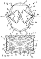
- FIGS. 13 and 14 illustrate an embodiment of a packing 1, which consists of five strips, however, based on their design and construction, that of the embodiment according to the FIGS. 11 and 12 , thus the strip 21, 22 and 23 corresponds.
- two outer strips 22 are provided, adjacent to and connected to the inside, two strips 21 and inwardly adjacent to and adjacent to a central strip 23.
- the orientation of the strips 22 and 23 according to the embodiment according to FIGS FIGS. 13 and 14 corresponds to the orientation of the strips 22 and 23 according to the embodiment of the FIGS. 11 and 12
- One of the strips 21 according to the embodiment of the FIGS. 13 and 14 corresponds in its orientation to the strip 21 according to the embodiment of the FIGS. 11 and 12
- the other strip 21 of the embodiment according to the FIGS. 13 and 14 rotated 180 ° about the axis 24 with respect to the other strip 21.
- the embodiment according to the FIGS. 15 to 17 is different from the one after the FIGS. 13 and 14 in that, starting from that according to the embodiment of the FIGS. 13 and 14 formed filler body 1, the two outer strips 22 are tilted at an angle about the axis 24, so that the two outer strips 22 are not parallel to each other and the holes 7 of these two strips 22 are closer than in the embodiment of the FIGS. 13 and 14 ,
- the design of the filling body 1 with the mutually inclined outer strips 22 has the advantage that the filler falls practically from all directions always in a very streamlined position and can not get caught in each other. It is also conceivable that only one of the two strips 22 is tilted at an angle about the axis 24.
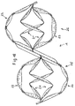
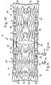
- the Figures 18 and 19 show a further embodiment of the filling body 1, by forming two packing according to the embodiment of the FIGS. 13 and 14 is formed, which are arranged rotated by 180 ° with respect to the axis 24 arranged with each other in the region of their facing end portions 18 are connected.
- the packing according to the embodiment of the Figures 18 and 19 made of a metal strip in the sense described above, and not by connecting two separate packing according to the embodiment of the FIGS. 13 and 14 educated.
- the filler body in its central region, between the two strips 21 and the strip 23 located therebetween of the respective filler half 25 and 26, an opening 27, the z. B. is designed as a wide, oval slot.
- the filler 1 is thus continuous only in the region of its outer strips 22 in the longitudinal direction.
- the passage of the two outer strips 22 over the entire length of the filling body 1, the stiff z. B. V-shaped central region and the connection of the individual strips in the region of their end regions 18 requires the required stability of the filling body 1, in particular against unwanted bending.
- the cut XX in FIG. 19 and the corresponding representation according to the FIGS. 20 and 21 is intended to illustrate that the individual strips of different cross-section, in particular a V-shaped cross-section according to FIG. 20 or a U-shaped cross-section as shown in the FIG. 21 can have.
- This cross-section is illustrated for the middle strip 23, but may well be verified in the other strips 21, 22.
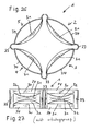
- the embodiment according to the FIGS. 22 and 23 represents a filling body 1, the z. B. a preliminary stage of the production of the filling body 1 according to the embodiment of the FIGS. 13 and 14 can be.
- the packing according to the embodiment according to the FIGS. 22 and 23 has the five interconnected strips 22, 21, 23, 21, 22, according to the embodiment of the FIGS. 13 and 14 are profiled, but these strips are not far down, up, or zig-zag-shaped bent, but it turns the filler 1 as a relatively flat element, in which the individual strips, in particular the outer strips 22 and the inner Strips 23 are only slightly bent out of the plane formed by the end portions 18.
- the embodiment according to the FIGS. 24 and 25 is different from the one after the FIGS. 22 and 23 essentially in that the inner strip 23 has a different shape. There, no U- or V-shaped profiling is provided, but it is the strip 23, based on its length, repeatedly cross-cut, so that a continuous middle strip portion 28 and side strip tabs 29 result. These tabs 29 are slightly pivoted out of the plane of the strip portion 28, based on adjacent lobes either in the same direction or in opposite directions. The inclination of the tabs 29 relative to the strip portion 28 may be different.
- FIGS. 26 and 27 show a non-inventive modified embodiment of a filling body 1.
- the elongated, narrow output sheet strip with four pairs of parallel cuts 30 is provided.
- the respective strip 31, which is associated with a pair of incisions 30, is crimped transversely to the longitudinal extent of the sheet metal strip, which results in a V-shaped or U-shaped constriction, so that between the strip 31, in its constricted area, and the respective incision 30, the opening 32 is formed.
- four partial elements 2 to 5 are formed in the filler body 1, which are arranged rotationally symmetrical. Between the sub-elements U-shaped profiles 33, transverse to the longitudinal extent of the metal strip, may be provided.
- the fourth profiling of the full circle of the filling body 1 may be formed in the region of the merged ends of the sheet metal strip, where the filling body 1 is opened. Consequently, the filler body 1, seen in cross-section, with its four strips 31 as quasi square, while the outside of the strips 31 adjacent strips 34 come to lie on a circle.
- All the aforementioned embodiments have in common that at least one opening 32 is formed between the bent strips, perpendicular to the plane passing through the cross-sections. This can be achieved by a profiling of the cross section or a punched.
- the strips do not touch, that is, for example, the embodiment of the FIGS. 13 and 14
- the outer strip 22 does not touch the inner strip 21 adjacent to it, and this does not touch the inner strip 21 adjacent to it, except for the connection of the strips in the region of the end regions 18 connecting the strips.
Landscapes
- Chemical & Material Sciences (AREA)
- Physics & Mathematics (AREA)
- Thermal Sciences (AREA)
- Organic Chemistry (AREA)
- Chemical Kinetics & Catalysis (AREA)
- Physical Or Chemical Processes And Apparatus (AREA)
Claims (12)
- Elément de garnissage (1) composé de métal, en particulier pour des colonnes d'échange de matière et/ou de chaleur, qui sont parcourues par un écoulement de gaz et/ou de liquide, dans lequel l'élément de garnissage (1) est produit à partir d'une plaque, et dans lequel il est prévu au moins une incision (30) dans la plaque pour la formation de deux bandes allongées (22, 21; 21, 23; 31, 34) entre des parties transversales (17, 18, 33) de la plaque, et les bandes sont courbées entre ces parties transversales hors du plan passant par les parties transversales, caractérisé en ce qu'au moins une ouverture (32) est formée entre les bandes courbées (22, 21; 21, 23; 31, 34), en regardant perpendiculairement au plan passant par les parties transversales (17, 18, 33), et au moins une bande (22, 21; 21, 23; 31, 34), par rapport à sa direction transversale, présente une section transversale profilée pour la formation de l'ouverture (32) et/ou présente un estampage latéral pour la formation de l'ouverture (32) et/ou les bandes (22, 21; 21, 23; 31, 34) sont disposées de façon inclinée l'une par rapport à l'autre, au moins dans des régions partielles, par rapport à leur direction transversale, pour la formation de l'ouverture (32).
- Elément de garnissage selon la revendication 1, caractérisé en ce qu'au moins une bande (22, 21; 21, 23; 31, 34) présente une section transversale en forme de U ou de V, par rapport à sa direction transversale.
- Elément de garnissage selon la revendication 1 ou 2, caractérisé en ce qu'au moins une bande (22, 21; 21, 23; 31, 34) présente des parties de bande (2, 3, 4, 5, 28) de section transversale différente, par rapport à sa direction longitudinale.
- Elément de garnissage selon l'une quelconque des revendications 1 à 3, caractérisé en ce qu'au moins une bande (22, 21; 21, 23; 31, 34) est munie d'au moins un trou de passage (6, 7, 8), en particulier dans une région de plus grande section transversale.
- Elément de garnissage selon la revendication 4, caractérisé en ce que le trou de passage (6, 7, 8) est muni d'un bourrelet (13).
- Elément de garnissage selon l'une quelconque des revendications 1 à 5, caractérisé en ce que la courbure de ladite au moins une bande (21, 22, 23, 31, 34) est réalisée sous la forme d'un coude.
- Elément de garnissage selon l'une quelconque des revendications 1 à 6, caractérisé en ce que la section transversale respective (17, 18, 33) est plane ou cintrée, en particulier en forme de V ou en forme de U.
- Elément de garnissage selon l'une quelconque des revendications 1 à 7, caractérisé en ce qu'il présente une structure de type grille.
- Elément de garnissage selon l'une quelconque des revendications 1 à 8, caractérisé en ce qu'il présente au moins trois bandes (22, 21, 23; 34, 31, 34), en particulier cinq bandes (22, 21, 23, 21, 22).
- Elément de garnissage selon l'une quelconque des revendications 1 à 9, caractérisé en ce qu'au moins une des bandes extérieures (22) est incurvée en direction de l'autre côté extérieur de l'élément de garnissage (1), en particulier dans un élément de garnissage (1) avec trois bandes ou dans un élément de garnissage avec cinq bandes, les deux bandes extérieures (22, 22) sont incurvées vers le milieu de l'élément de garnissage (1).
- Elément de garnissage selon l'une quelconque des revendications 1 à 10, caractérisé en ce que les parties transversales forment des parties d'extrémité (17, 18) de l'élément de garnissage.
- Elément de garnissage selon l'une quelconque des revendications 1 à 11, caractérisé en ce que les bandes courbées (21, 22, 23; 31, 34) ne se touchent pas.
Priority Applications (1)
| Application Number | Priority Date | Filing Date | Title |
|---|---|---|---|
| EP03028365.9A EP1541229B1 (fr) | 2003-12-10 | 2003-12-10 | Elément de garnissage pour l'échange de matière et de chaleur |
Applications Claiming Priority (1)
| Application Number | Priority Date | Filing Date | Title |
|---|---|---|---|
| EP03028365.9A EP1541229B1 (fr) | 2003-12-10 | 2003-12-10 | Elément de garnissage pour l'échange de matière et de chaleur |
Publications (2)
| Publication Number | Publication Date |
|---|---|
| EP1541229A1 EP1541229A1 (fr) | 2005-06-15 |
| EP1541229B1 true EP1541229B1 (fr) | 2014-09-03 |
Family
ID=34486171
Family Applications (1)
| Application Number | Title | Priority Date | Filing Date |
|---|---|---|---|
| EP03028365.9A Expired - Lifetime EP1541229B1 (fr) | 2003-12-10 | 2003-12-10 | Elément de garnissage pour l'échange de matière et de chaleur |
Country Status (1)
| Country | Link |
|---|---|
| EP (1) | EP1541229B1 (fr) |
Families Citing this family (5)
| Publication number | Priority date | Publication date | Assignee | Title |
|---|---|---|---|---|
| WO2013143629A1 (fr) * | 2012-03-27 | 2013-10-03 | Sulzer Chemtech Ag | Procédé de production d'un élément d'emballage et colonne ou réacteur comprenant ledit élément |
| US20140084496A1 (en) * | 2012-09-25 | 2014-03-27 | Robert Lawrence Miller | Packing element |
| AU2014344232B2 (en) * | 2013-10-30 | 2018-04-26 | Raschig Gmbh | Packing element, in particular for mass-transfer- and/or heat-exchange columns or towers |
| US9975106B2 (en) | 2013-10-30 | 2018-05-22 | Raschig Gmbh | Packing element for mass-transfer and/or heat-exchange columns or towers |
| DE102018119693A1 (de) | 2018-08-14 | 2020-02-20 | Rvt Process Equipment Gmbh | Füllkörper |
Citations (1)
| Publication number | Priority date | Publication date | Assignee | Title |
|---|---|---|---|---|
| US5543088A (en) * | 1994-12-29 | 1996-08-06 | Jaeger Products, Inc. | Random packing |
Family Cites Families (6)
| Publication number | Priority date | Publication date | Assignee | Title |
|---|---|---|---|---|
| DE335817C (de) * | 1920-01-15 | 1921-04-12 | Alfred Navratiel | Fuellkoerper fuer Absorptions-, Reaktions- oder Waschtuerme und aehnliche Einrichtungen |
| DE8330573U1 (de) * | 1983-10-25 | 1984-02-02 | Vereinigte Füllkörper-Fabriken GmbH & Co, 5412 Ransbach-Baumbach | Fuellkoerper fuer stoffaustauschkolonnen |
| US5200119A (en) * | 1985-04-11 | 1993-04-06 | Max Leva | Tower packing element |
| US5112536A (en) * | 1991-03-13 | 1992-05-12 | Koch Engineering Company, Inc. | Random packing element and method |
| ES2144178T3 (es) * | 1995-08-24 | 2000-06-01 | Raschig Gmbh | Cuerpo de relleno, especialmente para columnas o torres de intercambio de materia y/o de calor. |
| US6387534B1 (en) * | 2000-11-14 | 2002-05-14 | Saint-Gobain Norpro Corporation | Random packing element |
-
2003
- 2003-12-10 EP EP03028365.9A patent/EP1541229B1/fr not_active Expired - Lifetime
Patent Citations (1)
| Publication number | Priority date | Publication date | Assignee | Title |
|---|---|---|---|---|
| US5543088A (en) * | 1994-12-29 | 1996-08-06 | Jaeger Products, Inc. | Random packing |
Also Published As
| Publication number | Publication date |
|---|---|
| EP1541229A1 (fr) | 2005-06-15 |
Similar Documents
| Publication | Publication Date | Title |
|---|---|---|
| EP1216747B1 (fr) | Mélangeur statique | |
| EP2158027B2 (fr) | Elément de mélange statique | |
| DE60021509T3 (de) | Verdampfer mit verbessertem Kondensatablauf | |
| EP1530701A1 (fr) | Echangeur de chaleur, en particulier evaporateur pour installation de climatisation d'un vehicule | |
| DE10155045C2 (de) | Komponente zu einem statischen Mischer | |
| EP0221095B1 (fr) | Materiau de garnissage tourbillonnaire et procede de sa fabrication | |
| DE8330573U1 (de) | Fuellkoerper fuer stoffaustauschkolonnen | |
| EP1601915A2 (fr) | Dispositif de transfert de chaleur | |
| DE3049232A1 (de) | Strebe fuer kunststoffkanister | |
| EP1359331B1 (fr) | Profil d'écrou pour rail | |
| EP1541229A1 (fr) | Elément de garnissage pour l'échange de matière et de chaleur | |
| EP3583360B1 (fr) | Corps coulants | |
| EP3062924B1 (fr) | Garnissage, en particulier pour colonnes ou tours d'échange de matière et/ou de chaleur | |
| WO2012045438A2 (fr) | Sous-structure métallique de plafond | |
| DE69508324T2 (de) | Füllkörper | |
| EP3837044A1 (fr) | Corps de remplissage pourvu de lamelles à forme d'arc ou de vague asymétrique | |
| EP1731220B1 (fr) | Procédé de fabrication d'un élément de garnissage pour l'utilisation dans un appareil échangeur de masse et de chaleur et élément de garnissage obtenu par un tel procédé | |
| EP1771697A1 (fr) | Echangeur thermique, boite destinee a recevoir un fluide pour un echangeur thermique, et procede de production de cette boite | |
| CH653564A5 (de) | Stoffaustauschboden und verfahren zu dessen herstellung. | |
| DE10134312A1 (de) | Geordnete Packung für den Stoff- und Wärmeaustausch | |
| EP1731221A1 (fr) | Elément de remplissage composé de au moins deux unités plates | |
| DE3221129A1 (de) | Fuellkoerper fuer gas-fluessigkeitskontakt | |
| EP3290106A1 (fr) | Corps de remplissage | |
| EP4368415A1 (fr) | Bandage pneumatique pour véhicules | |
| EP0785019A1 (fr) | Garnissage pour colonne d'échange de matière |
Legal Events
| Date | Code | Title | Description |
|---|---|---|---|
| PUAI | Public reference made under article 153(3) epc to a published international application that has entered the european phase |
Free format text: ORIGINAL CODE: 0009012 |
|
| AK | Designated contracting states |
Kind code of ref document: A1 Designated state(s): AT BE BG CH CY CZ DE DK EE ES FI FR GB GR HU IE IT LI LU MC NL PT RO SE SI SK TR |
|
| AX | Request for extension of the european patent |
Extension state: AL LT LV MK |
|
| 17P | Request for examination filed |
Effective date: 20050629 |
|
| AKX | Designation fees paid |
Designated state(s): AT BE BG CH CY CZ DE DK EE ES FI FR GB GR HU IE IT LI LU MC NL PT RO SE SI SK TR |
|
| 17Q | First examination report despatched |
Effective date: 20110111 |
|
| GRAP | Despatch of communication of intention to grant a patent |
Free format text: ORIGINAL CODE: EPIDOSNIGR1 |
|
| GRAP | Despatch of communication of intention to grant a patent |
Free format text: ORIGINAL CODE: EPIDOSNIGR1 |
|
| INTG | Intention to grant announced |
Effective date: 20140616 |
|
| GRAS | Grant fee paid |
Free format text: ORIGINAL CODE: EPIDOSNIGR3 |
|
| GRAA | (expected) grant |
Free format text: ORIGINAL CODE: 0009210 |
|
| AK | Designated contracting states |
Kind code of ref document: B1 Designated state(s): AT BE BG CH CY CZ DE DK EE ES FI FR GB GR HU IE IT LI LU MC NL PT RO SE SI SK TR |
|
| REG | Reference to a national code |
Ref country code: GB Ref legal event code: FG4D Free format text: NOT ENGLISH |
|
| REG | Reference to a national code |
Ref country code: CH Ref legal event code: EP Ref country code: AT Ref legal event code: REF Ref document number: 685270 Country of ref document: AT Kind code of ref document: T Effective date: 20140915 |
|
| REG | Reference to a national code |
Ref country code: IE Ref legal event code: FG4D Free format text: LANGUAGE OF EP DOCUMENT: GERMAN |
|
| REG | Reference to a national code |
Ref country code: DE Ref legal event code: R096 Ref document number: 50315124 Country of ref document: DE Effective date: 20141016 |
|
| REG | Reference to a national code |
Ref country code: NL Ref legal event code: T3 |
|
| PG25 | Lapsed in a contracting state [announced via postgrant information from national office to epo] |
Ref country code: SE Free format text: LAPSE BECAUSE OF FAILURE TO SUBMIT A TRANSLATION OF THE DESCRIPTION OR TO PAY THE FEE WITHIN THE PRESCRIBED TIME-LIMIT Effective date: 20140903 Ref country code: GR Free format text: LAPSE BECAUSE OF FAILURE TO SUBMIT A TRANSLATION OF THE DESCRIPTION OR TO PAY THE FEE WITHIN THE PRESCRIBED TIME-LIMIT Effective date: 20141204 Ref country code: ES Free format text: LAPSE BECAUSE OF FAILURE TO SUBMIT A TRANSLATION OF THE DESCRIPTION OR TO PAY THE FEE WITHIN THE PRESCRIBED TIME-LIMIT Effective date: 20140903 Ref country code: FI Free format text: LAPSE BECAUSE OF FAILURE TO SUBMIT A TRANSLATION OF THE DESCRIPTION OR TO PAY THE FEE WITHIN THE PRESCRIBED TIME-LIMIT Effective date: 20140903 |
|
| PG25 | Lapsed in a contracting state [announced via postgrant information from national office to epo] |
Ref country code: CY Free format text: LAPSE BECAUSE OF FAILURE TO SUBMIT A TRANSLATION OF THE DESCRIPTION OR TO PAY THE FEE WITHIN THE PRESCRIBED TIME-LIMIT Effective date: 20140903 |
|
| PG25 | Lapsed in a contracting state [announced via postgrant information from national office to epo] |
Ref country code: SK Free format text: LAPSE BECAUSE OF FAILURE TO SUBMIT A TRANSLATION OF THE DESCRIPTION OR TO PAY THE FEE WITHIN THE PRESCRIBED TIME-LIMIT Effective date: 20140903 Ref country code: EE Free format text: LAPSE BECAUSE OF FAILURE TO SUBMIT A TRANSLATION OF THE DESCRIPTION OR TO PAY THE FEE WITHIN THE PRESCRIBED TIME-LIMIT Effective date: 20140903 Ref country code: PT Free format text: LAPSE BECAUSE OF FAILURE TO SUBMIT A TRANSLATION OF THE DESCRIPTION OR TO PAY THE FEE WITHIN THE PRESCRIBED TIME-LIMIT Effective date: 20150105 Ref country code: CZ Free format text: LAPSE BECAUSE OF FAILURE TO SUBMIT A TRANSLATION OF THE DESCRIPTION OR TO PAY THE FEE WITHIN THE PRESCRIBED TIME-LIMIT Effective date: 20140903 Ref country code: RO Free format text: LAPSE BECAUSE OF FAILURE TO SUBMIT A TRANSLATION OF THE DESCRIPTION OR TO PAY THE FEE WITHIN THE PRESCRIBED TIME-LIMIT Effective date: 20140903 |
|
| REG | Reference to a national code |
Ref country code: DE Ref legal event code: R097 Ref document number: 50315124 Country of ref document: DE |
|
| PLBE | No opposition filed within time limit |
Free format text: ORIGINAL CODE: 0009261 |
|
| STAA | Information on the status of an ep patent application or granted ep patent |
Free format text: STATUS: NO OPPOSITION FILED WITHIN TIME LIMIT |
|
| PG25 | Lapsed in a contracting state [announced via postgrant information from national office to epo] |
Ref country code: LU Free format text: LAPSE BECAUSE OF FAILURE TO SUBMIT A TRANSLATION OF THE DESCRIPTION OR TO PAY THE FEE WITHIN THE PRESCRIBED TIME-LIMIT Effective date: 20141210 Ref country code: DK Free format text: LAPSE BECAUSE OF FAILURE TO SUBMIT A TRANSLATION OF THE DESCRIPTION OR TO PAY THE FEE WITHIN THE PRESCRIBED TIME-LIMIT Effective date: 20140903 |
|
| REG | Reference to a national code |
Ref country code: CH Ref legal event code: PL |
|
| 26N | No opposition filed |
Effective date: 20150604 |
|
| REG | Reference to a national code |
Ref country code: IE Ref legal event code: MM4A |
|
| PG25 | Lapsed in a contracting state [announced via postgrant information from national office to epo] |
Ref country code: CH Free format text: LAPSE BECAUSE OF NON-PAYMENT OF DUE FEES Effective date: 20141231 Ref country code: IE Free format text: LAPSE BECAUSE OF NON-PAYMENT OF DUE FEES Effective date: 20141210 Ref country code: LI Free format text: LAPSE BECAUSE OF NON-PAYMENT OF DUE FEES Effective date: 20141231 |
|
| PG25 | Lapsed in a contracting state [announced via postgrant information from national office to epo] |
Ref country code: SI Free format text: LAPSE BECAUSE OF FAILURE TO SUBMIT A TRANSLATION OF THE DESCRIPTION OR TO PAY THE FEE WITHIN THE PRESCRIBED TIME-LIMIT Effective date: 20140903 |
|
| REG | Reference to a national code |
Ref country code: FR Ref legal event code: PLFP Year of fee payment: 13 |
|
| REG | Reference to a national code |
Ref country code: AT Ref legal event code: MM01 Ref document number: 685270 Country of ref document: AT Kind code of ref document: T Effective date: 20141210 |
|
| PG25 | Lapsed in a contracting state [announced via postgrant information from national office to epo] |
Ref country code: MC Free format text: LAPSE BECAUSE OF FAILURE TO SUBMIT A TRANSLATION OF THE DESCRIPTION OR TO PAY THE FEE WITHIN THE PRESCRIBED TIME-LIMIT Effective date: 20140903 Ref country code: BG Free format text: LAPSE BECAUSE OF FAILURE TO SUBMIT A TRANSLATION OF THE DESCRIPTION OR TO PAY THE FEE WITHIN THE PRESCRIBED TIME-LIMIT Effective date: 20140903 Ref country code: AT Free format text: LAPSE BECAUSE OF NON-PAYMENT OF DUE FEES Effective date: 20141210 |
|
| PG25 | Lapsed in a contracting state [announced via postgrant information from national office to epo] |
Ref country code: TR Free format text: LAPSE BECAUSE OF FAILURE TO SUBMIT A TRANSLATION OF THE DESCRIPTION OR TO PAY THE FEE WITHIN THE PRESCRIBED TIME-LIMIT Effective date: 20140903 Ref country code: HU Free format text: LAPSE BECAUSE OF FAILURE TO SUBMIT A TRANSLATION OF THE DESCRIPTION OR TO PAY THE FEE WITHIN THE PRESCRIBED TIME-LIMIT; INVALID AB INITIO Effective date: 20031210 |
|
| REG | Reference to a national code |
Ref country code: FR Ref legal event code: PLFP Year of fee payment: 14 |
|
| REG | Reference to a national code |
Ref country code: FR Ref legal event code: PLFP Year of fee payment: 15 |
|
| PGFP | Annual fee paid to national office [announced via postgrant information from national office to epo] |
Ref country code: FR Payment date: 20201223 Year of fee payment: 18 Ref country code: GB Payment date: 20201223 Year of fee payment: 18 |
|
| PGFP | Annual fee paid to national office [announced via postgrant information from national office to epo] |
Ref country code: BE Payment date: 20201221 Year of fee payment: 18 |
|
| PGFP | Annual fee paid to national office [announced via postgrant information from national office to epo] |
Ref country code: NL Payment date: 20201221 Year of fee payment: 18 |
|
| PGFP | Annual fee paid to national office [announced via postgrant information from national office to epo] |
Ref country code: IT Payment date: 20201224 Year of fee payment: 18 |
|
| PGFP | Annual fee paid to national office [announced via postgrant information from national office to epo] |
Ref country code: DE Payment date: 20210223 Year of fee payment: 18 |
|
| REG | Reference to a national code |
Ref country code: DE Ref legal event code: R119 Ref document number: 50315124 Country of ref document: DE |
|
| REG | Reference to a national code |
Ref country code: NL Ref legal event code: MM Effective date: 20220101 |
|
| GBPC | Gb: european patent ceased through non-payment of renewal fee |
Effective date: 20211210 |
|
| REG | Reference to a national code |
Ref country code: BE Ref legal event code: MM Effective date: 20211231 |
|
| PG25 | Lapsed in a contracting state [announced via postgrant information from national office to epo] |
Ref country code: NL Free format text: LAPSE BECAUSE OF NON-PAYMENT OF DUE FEES Effective date: 20220101 |
|
| PG25 | Lapsed in a contracting state [announced via postgrant information from national office to epo] |
Ref country code: GB Free format text: LAPSE BECAUSE OF NON-PAYMENT OF DUE FEES Effective date: 20211210 Ref country code: DE Free format text: LAPSE BECAUSE OF NON-PAYMENT OF DUE FEES Effective date: 20220701 |
|
| PG25 | Lapsed in a contracting state [announced via postgrant information from national office to epo] |
Ref country code: FR Free format text: LAPSE BECAUSE OF NON-PAYMENT OF DUE FEES Effective date: 20211231 Ref country code: BE Free format text: LAPSE BECAUSE OF NON-PAYMENT OF DUE FEES Effective date: 20211231 |
|
| PG25 | Lapsed in a contracting state [announced via postgrant information from national office to epo] |
Ref country code: IT Free format text: LAPSE BECAUSE OF NON-PAYMENT OF DUE FEES Effective date: 20211210 |