EP1541337A1 - Membrane et son procédé de fabrication - Google Patents
Membrane et son procédé de fabrication Download PDFInfo
- Publication number
- EP1541337A1 EP1541337A1 EP20030388083 EP03388083A EP1541337A1 EP 1541337 A1 EP1541337 A1 EP 1541337A1 EP 20030388083 EP20030388083 EP 20030388083 EP 03388083 A EP03388083 A EP 03388083A EP 1541337 A1 EP1541337 A1 EP 1541337A1
- Authority
- EP
- European Patent Office
- Prior art keywords
- foils
- mesh
- grid
- membrane
- bands
- Prior art date
- Legal status (The legal status is an assumption and is not a legal conclusion. Google has not performed a legal analysis and makes no representation as to the accuracy of the status listed.)
- Withdrawn
Links
- 239000012528 membrane Substances 0.000 title claims abstract description 193
- 238000000034 method Methods 0.000 title claims abstract description 122
- 239000011888 foil Substances 0.000 claims abstract description 292
- 239000000463 material Substances 0.000 claims abstract description 113
- 239000004744 fabric Substances 0.000 claims abstract description 92
- 230000003014 reinforcing effect Effects 0.000 claims abstract description 88
- 239000002861 polymer material Substances 0.000 claims abstract description 67
- 229920000642 polymer Polymers 0.000 claims abstract description 39
- 239000000835 fiber Substances 0.000 claims abstract description 28
- 239000010410 layer Substances 0.000 claims abstract description 19
- 239000002356 single layer Substances 0.000 claims abstract description 16
- 230000001747 exhibiting effect Effects 0.000 claims abstract description 9
- 239000002759 woven fabric Substances 0.000 claims abstract description 6
- 239000004745 nonwoven fabric Substances 0.000 claims abstract description 5
- -1 Polybutylene Polymers 0.000 claims description 54
- 239000004698 Polyethylene Substances 0.000 claims description 25
- 239000004743 Polypropylene Substances 0.000 claims description 23
- 229920000573 polyethylene Polymers 0.000 claims description 23
- 239000000203 mixture Substances 0.000 claims description 19
- 229920001155 polypropylene Polymers 0.000 claims description 18
- 238000010438 heat treatment Methods 0.000 claims description 17
- 238000010030 laminating Methods 0.000 claims description 16
- 238000000576 coating method Methods 0.000 claims description 15
- 239000011248 coating agent Substances 0.000 claims description 14
- 229920001400 block copolymer Polymers 0.000 claims description 12
- 229920001748 polybutylene Polymers 0.000 claims description 12
- 239000010687 lubricating oil Substances 0.000 claims description 11
- 230000001050 lubricating effect Effects 0.000 claims description 10
- 229920000728 polyester Polymers 0.000 claims description 10
- 239000004800 polyvinyl chloride Substances 0.000 claims description 10
- 238000001125 extrusion Methods 0.000 claims description 9
- 229920001903 high density polyethylene Polymers 0.000 claims description 9
- 239000004700 high-density polyethylene Substances 0.000 claims description 9
- 229920000139 polyethylene terephthalate Polymers 0.000 claims description 9
- 229920002943 EPDM rubber Polymers 0.000 claims description 8
- 229920000181 Ethylene propylene rubber Polymers 0.000 claims description 8
- 239000004952 Polyamide Substances 0.000 claims description 8
- 239000004433 Thermoplastic polyurethane Substances 0.000 claims description 8
- 238000010276 construction Methods 0.000 claims description 8
- 229920002647 polyamide Polymers 0.000 claims description 8
- 229920002635 polyurethane Polymers 0.000 claims description 8
- 239000004814 polyurethane Substances 0.000 claims description 8
- 229920000915 polyvinyl chloride Polymers 0.000 claims description 8
- 229920003048 styrene butadiene rubber Polymers 0.000 claims description 8
- 229920002803 thermoplastic polyurethane Polymers 0.000 claims description 8
- 229920002367 Polyisobutene Polymers 0.000 claims description 7
- 229920001577 copolymer Polymers 0.000 claims description 7
- 229920003020 cross-linked polyethylene Polymers 0.000 claims description 7
- 229920012485 Plasticized Polyvinyl chloride Polymers 0.000 claims description 6
- 229920006037 cross link polymer Polymers 0.000 claims description 6
- 229920005629 polypropylene homopolymer Polymers 0.000 claims description 6
- 238000005461 lubrication Methods 0.000 claims description 5
- 238000002844 melting Methods 0.000 claims description 5
- 230000008018 melting Effects 0.000 claims description 5
- 230000002902 bimodal effect Effects 0.000 claims description 4
- 238000009826 distribution Methods 0.000 claims description 4
- 239000002657 fibrous material Substances 0.000 claims description 4
- 229920005570 flexible polymer Polymers 0.000 claims description 4
- 229920002239 polyacrylonitrile Polymers 0.000 claims description 4
- 239000004677 Nylon Substances 0.000 claims description 3
- 229920001778 nylon Polymers 0.000 claims description 3
- 239000004642 Polyimide Substances 0.000 claims 4
- 229920001721 polyimide Polymers 0.000 claims 4
- 229920002451 polyvinyl alcohol Polymers 0.000 claims 2
- 235000019422 polyvinyl alcohol Nutrition 0.000 claims 2
- QNRATNLHPGXHMA-XZHTYLCXSA-N (r)-(6-ethoxyquinolin-4-yl)-[(2s,4s,5r)-5-ethyl-1-azabicyclo[2.2.2]octan-2-yl]methanol;hydrochloride Chemical compound Cl.C([C@H]([C@H](C1)CC)C2)CN1[C@@H]2[C@H](O)C1=CC=NC2=CC=C(OCC)C=C21 QNRATNLHPGXHMA-XZHTYLCXSA-N 0.000 claims 1
- 239000002131 composite material Substances 0.000 description 36
- 230000008569 process Effects 0.000 description 33
- 238000004519 manufacturing process Methods 0.000 description 17
- 239000000314 lubricant Substances 0.000 description 16
- 229920003023 plastic Polymers 0.000 description 16
- 239000004033 plastic Substances 0.000 description 16
- VGGSQFUCUMXWEO-UHFFFAOYSA-N Ethene Chemical compound C=C VGGSQFUCUMXWEO-UHFFFAOYSA-N 0.000 description 14
- 239000005977 Ethylene Substances 0.000 description 14
- 239000003921 oil Substances 0.000 description 14
- 239000003063 flame retardant Substances 0.000 description 11
- RNFJDJUURJAICM-UHFFFAOYSA-N 2,2,4,4,6,6-hexaphenoxy-1,3,5-triaza-2$l^{5},4$l^{5},6$l^{5}-triphosphacyclohexa-1,3,5-triene Chemical compound N=1P(OC=2C=CC=CC=2)(OC=2C=CC=CC=2)=NP(OC=2C=CC=CC=2)(OC=2C=CC=CC=2)=NP=1(OC=1C=CC=CC=1)OC1=CC=CC=C1 RNFJDJUURJAICM-UHFFFAOYSA-N 0.000 description 9
- 229920001684 low density polyethylene Polymers 0.000 description 9
- 239000004702 low-density polyethylene Substances 0.000 description 9
- XLYOFNOQVPJJNP-UHFFFAOYSA-N water Substances O XLYOFNOQVPJJNP-UHFFFAOYSA-N 0.000 description 8
- 238000003475 lamination Methods 0.000 description 7
- 229920001195 polyisoprene Polymers 0.000 description 7
- 229920002397 thermoplastic olefin Polymers 0.000 description 7
- 229920000034 Plastomer Polymers 0.000 description 6
- 230000005540 biological transmission Effects 0.000 description 6
- 239000004703 cross-linked polyethylene Substances 0.000 description 6
- 229920000092 linear low density polyethylene Polymers 0.000 description 6
- 229920001179 medium density polyethylene Polymers 0.000 description 6
- 239000004701 medium-density polyethylene Substances 0.000 description 6
- 229920005604 random copolymer Polymers 0.000 description 6
- 238000001228 spectrum Methods 0.000 description 6
- 229920001866 very low density polyethylene Polymers 0.000 description 6
- 239000002174 Styrene-butadiene Substances 0.000 description 5
- 230000008901 benefit Effects 0.000 description 5
- 239000011247 coating layer Substances 0.000 description 5
- 238000001816 cooling Methods 0.000 description 5
- 239000004711 α-olefin Substances 0.000 description 5
- BLDFSDCBQJUWFG-UHFFFAOYSA-N 2-(methylamino)-1,2-diphenylethanol Chemical compound C=1C=CC=CC=1C(NC)C(O)C1=CC=CC=C1 BLDFSDCBQJUWFG-UHFFFAOYSA-N 0.000 description 4
- BAPJBEWLBFYGME-UHFFFAOYSA-N Methyl acrylate Chemical compound COC(=O)C=C BAPJBEWLBFYGME-UHFFFAOYSA-N 0.000 description 4
- 239000004708 Very-low-density polyethylene Substances 0.000 description 4
- ADCOVFLJGNWWNZ-UHFFFAOYSA-N antimony trioxide Chemical compound O=[Sb]O[Sb]=O ADCOVFLJGNWWNZ-UHFFFAOYSA-N 0.000 description 4
- 150000001875 compounds Chemical class 0.000 description 4
- 229920001971 elastomer Polymers 0.000 description 4
- 238000005304 joining Methods 0.000 description 4
- 239000004707 linear low-density polyethylene Substances 0.000 description 4
- 229920000098 polyolefin Polymers 0.000 description 4
- 229920005606 polypropylene copolymer Polymers 0.000 description 4
- QQONPFPTGQHPMA-UHFFFAOYSA-N propylene Natural products CC=C QQONPFPTGQHPMA-UHFFFAOYSA-N 0.000 description 4
- 125000004805 propylene group Chemical group [H]C([H])([H])C([H])([*:1])C([H])([H])[*:2] 0.000 description 4
- 239000000126 substance Substances 0.000 description 4
- OKTJSMMVPCPJKN-UHFFFAOYSA-N Carbon Chemical compound [C] OKTJSMMVPCPJKN-UHFFFAOYSA-N 0.000 description 3
- 238000007792 addition Methods 0.000 description 3
- 229910052799 carbon Inorganic materials 0.000 description 3
- 238000005520 cutting process Methods 0.000 description 3
- 239000000806 elastomer Substances 0.000 description 3
- 239000012467 final product Substances 0.000 description 3
- 239000012943 hotmelt Substances 0.000 description 3
- 239000000047 product Substances 0.000 description 3
- 230000005855 radiation Effects 0.000 description 3
- 230000002787 reinforcement Effects 0.000 description 3
- 238000007789 sealing Methods 0.000 description 3
- 238000009958 sewing Methods 0.000 description 3
- 229920001169 thermoplastic Polymers 0.000 description 3
- 239000004416 thermosoftening plastic Substances 0.000 description 3
- SMZOUWXMTYCWNB-UHFFFAOYSA-N 2-(2-methoxy-5-methylphenyl)ethanamine Chemical compound COC1=CC=C(C)C=C1CCN SMZOUWXMTYCWNB-UHFFFAOYSA-N 0.000 description 2
- NIXOWILDQLNWCW-UHFFFAOYSA-N 2-Propenoic acid Natural products OC(=O)C=C NIXOWILDQLNWCW-UHFFFAOYSA-N 0.000 description 2
- XTXRWKRVRITETP-UHFFFAOYSA-N Vinyl acetate Chemical compound CC(=O)OC=C XTXRWKRVRITETP-UHFFFAOYSA-N 0.000 description 2
- 239000000853 adhesive Substances 0.000 description 2
- 230000001070 adhesive effect Effects 0.000 description 2
- 150000001412 amines Chemical class 0.000 description 2
- 238000010420 art technique Methods 0.000 description 2
- CQEYYJKEWSMYFG-UHFFFAOYSA-N butyl acrylate Chemical compound CCCCOC(=O)C=C CQEYYJKEWSMYFG-UHFFFAOYSA-N 0.000 description 2
- 238000004040 coloring Methods 0.000 description 2
- 238000004132 cross linking Methods 0.000 description 2
- 230000032798 delamination Effects 0.000 description 2
- 229920001038 ethylene copolymer Polymers 0.000 description 2
- 238000007765 extrusion coating Methods 0.000 description 2
- 230000001815 facial effect Effects 0.000 description 2
- 229920002457 flexible plastic Polymers 0.000 description 2
- 230000004927 fusion Effects 0.000 description 2
- 239000003365 glass fiber Substances 0.000 description 2
- 230000009477 glass transition Effects 0.000 description 2
- 229910052500 inorganic mineral Inorganic materials 0.000 description 2
- 229910000765 intermetallic Inorganic materials 0.000 description 2
- 239000004611 light stabiliser Substances 0.000 description 2
- 239000011707 mineral Substances 0.000 description 2
- 230000004048 modification Effects 0.000 description 2
- 238000012986 modification Methods 0.000 description 2
- 239000004014 plasticizer Substances 0.000 description 2
- 239000004810 polytetrafluoroethylene Substances 0.000 description 2
- 229920001343 polytetrafluoroethylene Polymers 0.000 description 2
- 239000000843 powder Substances 0.000 description 2
- GHMLBKRAJCXXBS-UHFFFAOYSA-N resorcinol Chemical compound OC1=CC=CC(O)=C1 GHMLBKRAJCXXBS-UHFFFAOYSA-N 0.000 description 2
- 239000002689 soil Substances 0.000 description 2
- 239000002904 solvent Substances 0.000 description 2
- 229940117958 vinyl acetate Drugs 0.000 description 2
- UKRDPEFKFJNXQM-UHFFFAOYSA-N vinylsilane Chemical compound [SiH3]C=C UKRDPEFKFJNXQM-UHFFFAOYSA-N 0.000 description 2
- 230000003313 weakening effect Effects 0.000 description 2
- 239000004114 Ammonium polyphosphate Substances 0.000 description 1
- 241000531908 Aramides Species 0.000 description 1
- BDYUCKRKPVLOEW-UHFFFAOYSA-N C=C.[SiH3]C=C Chemical group C=C.[SiH3]C=C BDYUCKRKPVLOEW-UHFFFAOYSA-N 0.000 description 1
- 239000004608 Heat Stabiliser Substances 0.000 description 1
- 239000004609 Impact Modifier Substances 0.000 description 1
- 229920000271 Kevlar® Polymers 0.000 description 1
- ABLZXFCXXLZCGV-UHFFFAOYSA-N Phosphorous acid Chemical compound OP(O)=O ABLZXFCXXLZCGV-UHFFFAOYSA-N 0.000 description 1
- OAICVXFJPJFONN-UHFFFAOYSA-N Phosphorus Chemical compound [P] OAICVXFJPJFONN-UHFFFAOYSA-N 0.000 description 1
- YSMRWXYRXBRSND-UHFFFAOYSA-N TOTP Chemical compound CC1=CC=CC=C1OP(=O)(OC=1C(=CC=CC=1)C)OC1=CC=CC=C1C YSMRWXYRXBRSND-UHFFFAOYSA-N 0.000 description 1
- WNROFYMDJYEPJX-UHFFFAOYSA-K aluminium hydroxide Chemical compound [OH-].[OH-].[OH-].[Al+3] WNROFYMDJYEPJX-UHFFFAOYSA-K 0.000 description 1
- 235000019826 ammonium polyphosphate Nutrition 0.000 description 1
- 229920001276 ammonium polyphosphate Polymers 0.000 description 1
- 239000003963 antioxidant agent Substances 0.000 description 1
- 229920003235 aromatic polyamide Polymers 0.000 description 1
- 230000004888 barrier function Effects 0.000 description 1
- 230000015572 biosynthetic process Effects 0.000 description 1
- 239000003086 colorant Substances 0.000 description 1
- 238000005336 cracking Methods 0.000 description 1
- 238000011161 development Methods 0.000 description 1
- 230000018109 developmental process Effects 0.000 description 1
- 238000004049 embossing Methods 0.000 description 1
- 239000003292 glue Substances 0.000 description 1
- 239000010439 graphite Substances 0.000 description 1
- 229910002804 graphite Inorganic materials 0.000 description 1
- 230000010354 integration Effects 0.000 description 1
- 230000002427 irreversible effect Effects 0.000 description 1
- 230000000670 limiting effect Effects 0.000 description 1
- 230000007774 longterm Effects 0.000 description 1
- VTHJTEIRLNZDEV-UHFFFAOYSA-L magnesium dihydroxide Chemical compound [OH-].[OH-].[Mg+2] VTHJTEIRLNZDEV-UHFFFAOYSA-L 0.000 description 1
- 239000000347 magnesium hydroxide Substances 0.000 description 1
- 229910001862 magnesium hydroxide Inorganic materials 0.000 description 1
- OJURWUUOVGOHJZ-UHFFFAOYSA-N methyl 2-[(2-acetyloxyphenyl)methyl-[2-[(2-acetyloxyphenyl)methyl-(2-methoxy-2-oxoethyl)amino]ethyl]amino]acetate Chemical compound C=1C=CC=C(OC(C)=O)C=1CN(CC(=O)OC)CCN(CC(=O)OC)CC1=CC=CC=C1OC(C)=O OJURWUUOVGOHJZ-UHFFFAOYSA-N 0.000 description 1
- 230000002093 peripheral effect Effects 0.000 description 1
- 230000035699 permeability Effects 0.000 description 1
- 150000003014 phosphoric acid esters Chemical class 0.000 description 1
- 239000000049 pigment Substances 0.000 description 1
- 238000003825 pressing Methods 0.000 description 1
- 230000002829 reductive effect Effects 0.000 description 1
- 239000002990 reinforced plastic Substances 0.000 description 1
- 239000005060 rubber Substances 0.000 description 1
- 239000007787 solid Substances 0.000 description 1
- 230000003019 stabilising effect Effects 0.000 description 1
- 239000003381 stabilizer Substances 0.000 description 1
- 230000003068 static effect Effects 0.000 description 1
- 239000002344 surface layer Substances 0.000 description 1
- 229920002725 thermoplastic elastomer Polymers 0.000 description 1
- XZZNDPSIHUTMOC-UHFFFAOYSA-N triphenyl phosphate Chemical compound C=1C=CC=CC=1OP(OC=1C=CC=CC=1)(=O)OC1=CC=CC=C1 XZZNDPSIHUTMOC-UHFFFAOYSA-N 0.000 description 1
- BIKXLKXABVUSMH-UHFFFAOYSA-N trizinc;diborate Chemical compound [Zn+2].[Zn+2].[Zn+2].[O-]B([O-])[O-].[O-]B([O-])[O-] BIKXLKXABVUSMH-UHFFFAOYSA-N 0.000 description 1
- 230000007306 turnover Effects 0.000 description 1
- 238000009423 ventilation Methods 0.000 description 1
- 238000003466 welding Methods 0.000 description 1
- DXZMANYCMVCPIM-UHFFFAOYSA-L zinc;diethylphosphinate Chemical compound [Zn+2].CCP([O-])(=O)CC.CCP([O-])(=O)CC DXZMANYCMVCPIM-UHFFFAOYSA-L 0.000 description 1
Images





Classifications
-
- B—PERFORMING OPERATIONS; TRANSPORTING
- B32—LAYERED PRODUCTS
- B32B—LAYERED PRODUCTS, i.e. PRODUCTS BUILT-UP OF STRATA OF FLAT OR NON-FLAT, e.g. CELLULAR OR HONEYCOMB, FORM
- B32B27/00—Layered products comprising a layer of synthetic resin
- B32B27/12—Layered products comprising a layer of synthetic resin next to a fibrous or filamentary layer
-
- A—HUMAN NECESSITIES
- A01—AGRICULTURE; FORESTRY; ANIMAL HUSBANDRY; HUNTING; TRAPPING; FISHING
- A01G—HORTICULTURE; CULTIVATION OF VEGETABLES, FLOWERS, RICE, FRUIT, VINES, HOPS OR SEAWEED; FORESTRY; WATERING
- A01G9/00—Cultivation in receptacles, forcing-frames or greenhouses; Edging for beds, lawn or the like
- A01G9/14—Greenhouses
- A01G9/1438—Covering materials therefor; Materials for protective coverings used for soil and plants, e.g. films, canopies, tunnels or cloches
-
- B—PERFORMING OPERATIONS; TRANSPORTING
- B32—LAYERED PRODUCTS
- B32B—LAYERED PRODUCTS, i.e. PRODUCTS BUILT-UP OF STRATA OF FLAT OR NON-FLAT, e.g. CELLULAR OR HONEYCOMB, FORM
- B32B3/00—Layered products comprising a layer with external or internal discontinuities or unevennesses, or a layer of non-planar shape; Layered products comprising a layer having particular features of form
- B32B3/02—Layered products comprising a layer with external or internal discontinuities or unevennesses, or a layer of non-planar shape; Layered products comprising a layer having particular features of form characterised by features of form at particular places, e.g. in edge regions
- B32B3/06—Layered products comprising a layer with external or internal discontinuities or unevennesses, or a layer of non-planar shape; Layered products comprising a layer having particular features of form characterised by features of form at particular places, e.g. in edge regions for securing layers together; for attaching the product to another member, e.g. to a support, or to another product, e.g. groove/tongue, interlocking
-
- B—PERFORMING OPERATIONS; TRANSPORTING
- B32—LAYERED PRODUCTS
- B32B—LAYERED PRODUCTS, i.e. PRODUCTS BUILT-UP OF STRATA OF FLAT OR NON-FLAT, e.g. CELLULAR OR HONEYCOMB, FORM
- B32B3/00—Layered products comprising a layer with external or internal discontinuities or unevennesses, or a layer of non-planar shape; Layered products comprising a layer having particular features of form
- B32B3/02—Layered products comprising a layer with external or internal discontinuities or unevennesses, or a layer of non-planar shape; Layered products comprising a layer having particular features of form characterised by features of form at particular places, e.g. in edge regions
- B32B3/08—Layered products comprising a layer with external or internal discontinuities or unevennesses, or a layer of non-planar shape; Layered products comprising a layer having particular features of form characterised by features of form at particular places, e.g. in edge regions characterised by added members at particular parts
-
- B—PERFORMING OPERATIONS; TRANSPORTING
- B32—LAYERED PRODUCTS
- B32B—LAYERED PRODUCTS, i.e. PRODUCTS BUILT-UP OF STRATA OF FLAT OR NON-FLAT, e.g. CELLULAR OR HONEYCOMB, FORM
- B32B5/00—Layered products characterised by the non- homogeneity or physical structure, i.e. comprising a fibrous, filamentary, particulate or foam layer; Layered products characterised by having a layer differing constitutionally or physically in different parts
- B32B5/02—Layered products characterised by the non- homogeneity or physical structure, i.e. comprising a fibrous, filamentary, particulate or foam layer; Layered products characterised by having a layer differing constitutionally or physically in different parts characterised by structural features of a fibrous or filamentary layer
- B32B5/022—Non-woven fabric
-
- B—PERFORMING OPERATIONS; TRANSPORTING
- B32—LAYERED PRODUCTS
- B32B—LAYERED PRODUCTS, i.e. PRODUCTS BUILT-UP OF STRATA OF FLAT OR NON-FLAT, e.g. CELLULAR OR HONEYCOMB, FORM
- B32B5/00—Layered products characterised by the non- homogeneity or physical structure, i.e. comprising a fibrous, filamentary, particulate or foam layer; Layered products characterised by having a layer differing constitutionally or physically in different parts
- B32B5/02—Layered products characterised by the non- homogeneity or physical structure, i.e. comprising a fibrous, filamentary, particulate or foam layer; Layered products characterised by having a layer differing constitutionally or physically in different parts characterised by structural features of a fibrous or filamentary layer
- B32B5/024—Woven fabric
-
- E—FIXED CONSTRUCTIONS
- E04—BUILDING
- E04D—ROOF COVERINGS; SKY-LIGHTS; GUTTERS; ROOF-WORKING TOOLS
- E04D12/00—Non-structural supports for roofing materials, e.g. battens, boards
- E04D12/002—Sheets of flexible material, e.g. roofing tile underlay
-
- B—PERFORMING OPERATIONS; TRANSPORTING
- B32—LAYERED PRODUCTS
- B32B—LAYERED PRODUCTS, i.e. PRODUCTS BUILT-UP OF STRATA OF FLAT OR NON-FLAT, e.g. CELLULAR OR HONEYCOMB, FORM
- B32B2419/00—Buildings or parts thereof
- B32B2419/06—Roofs, roof membranes
-
- Y—GENERAL TAGGING OF NEW TECHNOLOGICAL DEVELOPMENTS; GENERAL TAGGING OF CROSS-SECTIONAL TECHNOLOGIES SPANNING OVER SEVERAL SECTIONS OF THE IPC; TECHNICAL SUBJECTS COVERED BY FORMER USPC CROSS-REFERENCE ART COLLECTIONS [XRACs] AND DIGESTS
- Y02—TECHNOLOGIES OR APPLICATIONS FOR MITIGATION OR ADAPTATION AGAINST CLIMATE CHANGE
- Y02A—TECHNOLOGIES FOR ADAPTATION TO CLIMATE CHANGE
- Y02A40/00—Adaptation technologies in agriculture, forestry, livestock or agroalimentary production
- Y02A40/10—Adaptation technologies in agriculture, forestry, livestock or agroalimentary production in agriculture
- Y02A40/25—Greenhouse technology, e.g. cooling systems therefor
-
- Y—GENERAL TAGGING OF NEW TECHNOLOGICAL DEVELOPMENTS; GENERAL TAGGING OF CROSS-SECTIONAL TECHNOLOGIES SPANNING OVER SEVERAL SECTIONS OF THE IPC; TECHNICAL SUBJECTS COVERED BY FORMER USPC CROSS-REFERENCE ART COLLECTIONS [XRACs] AND DIGESTS
- Y10—TECHNICAL SUBJECTS COVERED BY FORMER USPC
- Y10T—TECHNICAL SUBJECTS COVERED BY FORMER US CLASSIFICATION
- Y10T442/00—Fabric [woven, knitted, or nonwoven textile or cloth, etc.]
- Y10T442/10—Scrim [e.g., open net or mesh, gauze, loose or open weave or knit, etc.]
-
- Y—GENERAL TAGGING OF NEW TECHNOLOGICAL DEVELOPMENTS; GENERAL TAGGING OF CROSS-SECTIONAL TECHNOLOGIES SPANNING OVER SEVERAL SECTIONS OF THE IPC; TECHNICAL SUBJECTS COVERED BY FORMER USPC CROSS-REFERENCE ART COLLECTIONS [XRACs] AND DIGESTS
- Y10—TECHNICAL SUBJECTS COVERED BY FORMER USPC
- Y10T—TECHNICAL SUBJECTS COVERED BY FORMER US CLASSIFICATION
- Y10T442/00—Fabric [woven, knitted, or nonwoven textile or cloth, etc.]
- Y10T442/10—Scrim [e.g., open net or mesh, gauze, loose or open weave or knit, etc.]
- Y10T442/102—Woven scrim
- Y10T442/133—Inorganic fiber-containing scrim
- Y10T442/14—Including an additional scrim layer
-
- Y—GENERAL TAGGING OF NEW TECHNOLOGICAL DEVELOPMENTS; GENERAL TAGGING OF CROSS-SECTIONAL TECHNOLOGIES SPANNING OVER SEVERAL SECTIONS OF THE IPC; TECHNICAL SUBJECTS COVERED BY FORMER USPC CROSS-REFERENCE ART COLLECTIONS [XRACs] AND DIGESTS
- Y10—TECHNICAL SUBJECTS COVERED BY FORMER USPC
- Y10T—TECHNICAL SUBJECTS COVERED BY FORMER US CLASSIFICATION
- Y10T442/00—Fabric [woven, knitted, or nonwoven textile or cloth, etc.]
- Y10T442/10—Scrim [e.g., open net or mesh, gauze, loose or open weave or knit, etc.]
- Y10T442/102—Woven scrim
- Y10T442/133—Inorganic fiber-containing scrim
- Y10T442/145—Including a preformed film, foil, or sheet
Definitions
- the present invention relates generally to the technical field of membranes and a method of producing membranes, in particular weather protection membranes.
- the present invention relates in particular to a method of producing membranes for use in the field of house building or construction and integrally including edge reinforcing bands such as 'Keder' bands for fixating the membranes to supporting structures such as scaffolds, etc.
- the membranes may be used as a scaffold sheeting, a temporary roof cover, an underroof membrane, tarpaulins, geo membranes, world aid shelters, military shelters, green house or agricultural membranes, festival or leisure tents, etc.
- the present invention also relates to the membrane, in particular a weather protection membrane.
- the membranes In the use of membranes, such as weather protection or scaffold membranes for house buildings, the membranes have to fulfil certain requirements in relation to the intentional use of the membranes and also the application of the membranes at the building sites such as requirements in relation to puncture resistance of the membrane structure which characteristic may be measured according to specific requirements or standards. Consequently, the membranes have to comply with certain requirements as to strength, as defined in relevant ISO, BS, EN or DIN standards and have additionally to fulfil certain additional characteristics, which are often difficult to measure or specifically determine, which characteristics are, however, within the industry, often referred to as toughness, crack resistance, abrasive resistance, draping and noise characteristics.
- the membranes to be used in the construction industry or equivalent industries have, apart from the above properties, also to be easily folded and comply with certain physical configurations and therefore, the membranes have to fulfil certain standards, as to draping, known from the clothing industry as a term, and further, the membranes to be used in housings, need to be extremely flexible and lightweight for allowing the workers to handle the membranes at the building site without damaging by puncturing, distorting, ripping the membranes and still further, should be of a type preventing the membranes from generating noise provided the membranes be exposed to wind pressure, fluctuation from ventilation air, impact or other mechanical influence, even below roofing materials such as tiles.
- the membranes should, for obvious reasons, exhibit characteristics preventing the membranes from cracking or being torn apart through abrasive impact and still further should be resistant to delamination.
- the relevant building membranes are further to constitute watertight or in certain applications waterproof structures.
- membranes of the above kind are within this technique field of scaffold structures in which the membranes are provided with an edge reinforcement band in which a flexible string commonly known as a 'Keder' string is enclosed by means of which the membrane may be suspended between two hollow profiled bearing elements constituting additional components or integral parts of the scaffold.
- edge reinforcement band in which a flexible string commonly known as a 'Keder' string is enclosed by means of which the membrane may be suspended between two hollow profiled bearing elements constituting additional components or integral parts of the scaffold.
- the publication US 6,145,526 describes a system for securing a fabric cover of a fabric covered building to a framework or foundation of the building.
- a tie-down member is fastened so as to extent substantially from one end of the fabric cover to the opposite end.
- the member is most conveniently a pipe inserted in pockets formed along the side of the fabric cover, the member being exposed at intervals by cut-outs in the pockets.
- the pockets may be formed and fastened by sewing.
- the punctures in the fabric that result from the sewing may cause water ingress and heat-sealing of the fabric may be used to form the pockets for providing a stronger seam with no punctures to weaken the fabric at the seam.
- the publication US 6,564,513 describes a building structure of the type comprising arched frame members supporting panels of flexible material such as weather resistant fabric.
- the flexible material is provided with means for attachment to a connecting member.
- the connecting member comprises means for slidably engaging the attachments of the flexible material.
- the prior art technique of producing scaffold membranes for use in combination with a supporting scaffold or grid structure and having edgewise extending 'Keder' bands is based on a manual technique of stitching and sewing the 'Keder' bands to the edge parts of the membrane after the membrane has been cut into a specific size.
- the technique of manually producing the scaffold membrane by utilising e.g. the high strength and high compliance composite grid reinforced membranes described in the applicant's above identified international patent application has not to any substantial extent been industrialised or automated as the origin of the 'Keder' band is the sail manufactory industry in which sails generally have been produced manually according to the specific requirements of the boat owner and for complying with specific dimensions of the boat in question.
- a membrane in particular a membrane, in particular a weather protection membrane for use in the field of house building or construction, in particular for use as a scaffold membrane, scaffold sheeting, tarpaulins, an underroof cover, a temporary roof cover, geo membranes, world aid shelters, military shelters, green house or agricultural membranes, festival or leisure tents, etc., comprising:
- two bands of polymer materials preferably weather resistant polymer materials exhibiting fairly low frictional properties are laminated between the two foils of the composite foil assembly or to the one side being the top surface or the bottom surface of the composite foil assembly by utilising the facility of the production process of producing the composite fabric, grid, mesh or scrim reinforced membrane for integrally producing the edge reinforcing band as an integral part of the membrane structure.
- the two bands of polymer materials which are laminated to the sandwiched structure or into the sandwiched structure through one of the foils or alternatively between the two foils, respectively are positioned so as to establish an overlap between said bands and said reinforcing fabric, grid, mesh or scrim.
- the membranes produced according to the present invention are intended to be used as scaffold sheeting or used for similar application in which the membrane may be exposed to even extreme weather conditions including rough wind or storm and heavy rain or snow. Consequently, in a scaffold covering structure in which the membranes are mounted by means of 'Keder' strings included in the edge reinforcing bands characteristic of the present invention, the overall structure including the junction between the edge reinforcing bands and the composite foil assembly have to allow the structure to have high impact resistance.
- Fabric, grid, mesh or scrim are to be construed comprising any fibre, filament, tape or wire structure of plastics material or any other relevant material, such as e.g. carbon reinforced plastic material etc. which exhibits an overall geometrical configuration resembling a fabric, grid, mesh or scrim or any other structure differing from a conventional fabric, grid, mesh or scrim, still fulfilling the same purpose as a reinforcing fabric, grid, mesh or scrim.
- the fabric, grid, mesh or scrim may have any appropriate configuration and also have varying dimensions and all embodiments complying with the above definition are consequently to be considered covered by the term fabric, grid, mesh or scrim.
- a relevant lifetime for membranes to be used in the construction industry in general is often of the order of a few months to a few years for the intentional application, being a temporary application and a so called permanent application, respectively, e.g. including 10 - 30 years, 30 - 50 years or even 50 - 100 years.
- the terms weather resistance and weather protection are, in accordance with the above statements, to be considered in the context of the intentional use of the membrane or the membranes in question.
- the weather resistance or weather protection ability is to be considered in conjunction with the relevant lifetime of the membrane or the membranes in question, which lifetime is typically of the order of a maximum of 1-2 years.
- the expression weather resistance means that within the relevant lifetime, the membrane is resistant to the weather conditions including the wind, any rain or snow and also the exposure to the sun as the UV radiation from the sun deteriorates the membrane materials.
- an underroof membrane which is not exposed to the sunlight may, for the relevant lifetime of the order of 30-50 years or even more, be resistant to the exposure of wind and also water due to rain and snow and even the temperature variation from e.g. - 40°C to + 40°C or even larger temperature variations.
- foil and membrane which in some aspects may be considered synonymous, are distinctly used for separate intentional purposes.
- the term foil is used as the term defining an element or rather two elements of an overall foil or sheet configuration, which elements are together with the fabric, grid, mesh or scrim, composed into a composite structure constituting the membrane. It is to be understood that the foils which are combined with the reinforcing fabric, mesh, grid or scrim for establishing the membrane may themselves constitute membranes and be composed of individual foils, sheets, reinforcing fibres, fabrics, grids, meshes or scrims without deviating from the meaning of the term foil as used in the present context.
- the membrane according to the present invention may for other applications be considered constituting a foil or alternatively a sheet and the interpretation of the membrane as a foil or a sheet is not to be construed limiting in the present context.
- the method further comprises prior to the interlaying and sandwiching of the reinforcing fabric, grid, mesh or scrim or grid between the first and second foils, the step of applying a lubricating material such as a lubricating oil or wax which is substantially non-aggressive to the polymer materials of the first and second foils and substantially non-dissolvable within the polymer materials of the first and second foils to at least a part of the fabric, grid, mesh or scrim for at least partly coating the fabric, grid, mesh or scrim with the lubricating material, and including in the step of interlaying and sandwiching the reinforcing fabric, grid, mesh or scrim provided with the lubricating material coating between the first and the second foils for allowing the lubricating material coated reinforcing fabric, grid, mesh or scrim to be movable relative to the first and second sandwiching foils within the sandwich structure.
- a lubricating material such as a lubricating oil or wax which is substantially non-aggressive to the polymer materials
- the combination of the integral bands and the loosely positioned grid or mesh as described in greater details in applicant's above mentioned international patent application allows the composite foil assembly to accommodate the mechanical stresses transmitted or generated by the mechanical fixation of the bands relative to the supporting structure such as the supporting scaffold. Consequently, it is contemplated that the integration of the edge reinforcing bands into the composite foil assembly may only be provided without risking the mechanical strength of the composite foil assembly provided the composite foil assembly be produced in accordance with the teachings of applicant's above mentioned international patent application, i.e. including the loosely positioned reinforcing fabric, grid, mesh or scrim.
- the two foils used in the composite foil assembly and serving as a fixture for the edge reinforcing bands characteristic of the present invention may be produced as separate pre-fabricated foils which are pre-extruded and pre-hardened foils and laminated together in the sandwich structure according to the teachings of the present invention as defined above.
- At least one of the foils laminated together in the sandwich structure is extruded in conjunction with or prior to the step of laminating the first and second foil together in the sandwich structure according to the teachings of the present invention and consequently constitutes a soft foil for fastening the bands in the step of laminating the bands to the first and/or the second foil.
- the step of laminating the bands to the composite foil structure may comprise laminating the bands between the two foils or laminating the bands to the one side of one of the two foils being the top or the bottom foil constituting the first or the second foil.
- the bands may be contacted with the reinforcing fabric, grid, mesh or scrim, or alternatively, when laminated to the top side or bottom side of the composite foil structure be prevented from being contacted with the fabric, grid, mesh or scrim.
- the bands should as discussed above, be positioned overlapping with the reinforcing fabric in order to provide a sufficient mechanical stability and strength of the composite membrane structure.
- the overlapping area between the fabric, grid, mesh or scrim and the bands must be provided.
- a particular aspect of the present invention relates to the production of 'Keder' reinforced bands as 'Keder' strings are commonly used within the technical field of scaffold sheeting as the term is used in this context as a generic term covering any mechanical structure in which an enlarged part of the reinforcing bands of the membrane serves as a guiding and arresting body to be positioned in a slot of a supporting structure such as a structural element of a scaffold.
- 'Keder' strings are cords, cylindrical bodies, braided or twisted ropes, etc.
- the term flexible when used in the present context means bendable but not elastically stretchable.
- the term 'Keder' as originally used within the sail production field is a generic term covering the relevant field of fixating a sail or a similar element in the present context a weather protection membrane by means of a large body part which is received within a guiding rail or similar receiving structure.
- the bands may alternatively be used for mechanical fixation for fasteners such as zipper-like fastening elements, burr fasteners or mechanical eyelets, etc.
- the bands serving as 'Keder' bands may themselves be provided as fabrics, grids, meshes or scrims provided with one or two foil layers or foil coatings be provided as single polymer foil layers, multilayers, or composite structures including an integral fabric, grid, mesh or scrim and per se produced in accordance with the technique described in applicant's above mentioned published international patent application or any other technique of providing a laminated and/or composite membrane structure.
- the reinforcing bands to be laminated to the composite foil assembly may be perforated or provided with through-going apertures in which case the reinforcing bands are preferably sandwiched between the two foils for allowing the two foils to be mechanically bonded together through the perforations or apertures and thereby providing a mechanical sealing between the two outer foils, i.e. the first and the second foil.
- band is to be construed a generic term covering any narrow band as compared to the width of the foils in question which band may be made from a high strength and preferably low frictional material of polymer base such as the materials used for the first and second foil and optionally provided with a frictional surface coating such as a PTFE fluorpolymer coating or similar coating or having interlayered fibres of woven threads of low frictional material such as the above mentioned PTFE fibres.
- bands being made from PE, preferably HDPE, PP, preferably isotactic polypropylene homopolymer; TPO; POP; Polybutylene (Poly(1-butene)); block copolymers; crosslinked polymers such as EPDM, SBR, EPR, PIB, PEX, PIP, polyisobutylene and TPU; Plasticized PVC ; Polyester, preferably Polyethylene, polyethylenterephthalat (PET) and blends or mixtures of any of the above, preferably having a bimodal molecular weight distribution, being block copolymers or combinations of block and copolymers, and/or including low frictional fibres.
- PE preferably HDPE, PP, preferably isotactic polypropylene homopolymer
- TPO polypropylene homopolymer
- POP Polybutylene (Poly(1-butene)); block copolymers
- crosslinked polymers such as EPDM, SBR, EPR, PIB, PEX
- the material PET is particularly preferred provided the bands be provided as non-reinforced single- or multilayer membranes, however, provided a reinforced structure including a fabric, grid, mesh or scrim be provided, PP, HDPE may advantageously be used.
- the bands may, as mentioned above, be constituted by single foils, reinforced or non-reinforced composite foil structures or alternatively be constituted by woven or non-woven PET, PP or PE fabrics.
- the membrane preferably exhibits a tensile strength of the order of more than 600 N/50 mm width, preferably more than 1000 N/50 mm width, such as more than 1500 N/50 mm or even more than 2000 N/50 mm (measured according to EN 12311-1) also preferably exhibits a puncture resistance pr. thickness of more than 250 N/mm thickness, preferably more than 300 N/mm or even more than 350 N/mm (according to NT Build 336/1988-9 except with a 10 mm chisel).
- the fabric, mesh, grid or scrim of the composite membrane may be made from any appropriate polymer fibre, filament, tape or wire material, e.g. the materials polypropylene, preferably isotactic polypropylene, polyethylene, preferably high density polyethylene, polyester or polyesters, preferably polyethylene terephtalene (PET), polyamide or polyamides, polyacrylonitrile or polyurethane or polyurethanes or a combination of the above materials. Additionally, fibres of carbon fibre, aramide fibres (Kevlar®), glass fibres etc. commonly used for reinforcing purposes within the plastics industry may be alternatively be used for the fabric, grid, mesh or scrim of the composite membrane.
- polypropylene preferably isotactic polypropylene
- polyethylene preferably high density polyethylene
- polyester or polyesters preferably polyethylene terephtalene (PET)
- PET polyethylene terephtalene
- polyamide or polyamides polyacrylonitrile or polyure
- the reinforcing fabric, grid, mesh or scrim has to exhibit specific properties as to strength, which properties are predominantly determined by the material of the reinforcing fabric, grid, mesh or scrim in question and the dimensions and size of the fabric, grid, mesh or scrim material.
- the reinforcing fabric, grid, mesh or scrim may be made from a polymer fibre, filament or wire material of a thickness of 0.1 - 1 mm, preferably 0.1 - 0.4 mm or of a thickness of 0.1 - 0.15 mm, 0.15 - 0.2 mm, 0.2 - 0.25 mm, 0.25 - 0.3 mm, 0.3 - 0.35 mm, 0.35 - 0.4 mm, 0.4 - 0.45 mm, 0.45 - 0.5 mm, 0.5 - 0.55 mm, 0.55 - 0.6 mm, 0.6 - 0.65 mm, 0.65 - 0.7 mm (if circular), and/or the reinforcing fabric, grid, mesh or scrim being made of polymer fibre
- 1000 - 3000 dtex preferably 1500 - 2500 dtex, or of a thickness of 300 - 400 dtex, 400 - 500 dtex, 500 - 600 dtex, 600 - 700 dtex, 700 - 800 dtex, 800 - 900 dtex, 900 - 1000 dtex, 1000 - 1250 dtex, 1250 - 1500 dtex, 1500 - 1750 dtex, 1750 - 2000 dtex, 2000 - 2500 dtex, 2500 - 3000 dtex, 3000 -3500 dtex or 3500 - 4000 dtex.
- the fabric, grid, mesh or scrim itself has to define a fabric, grid, mesh or scrim structure of an appropriate configuration and size and according to presently preferred and advantageous embodiments of the membrane, the mesh preferably and advantageously defines a mesh size of the order of 2 - 40 mm, such as 4 - 12 mm, preferably 3 - 10 mm, such as approximately 10 mm, or a mesh size of the order of 2 - 3 mm, 3 - 5 mm, 5 - 7 mm, 7 - 9 mm, 9 - 11 mm, 11 - 13 mm, 13 - 15 mm, 15 - 20 mm, 20 - 25 mm, 25 -30 mm, 30 - 35 mm or 35 - 40 mm.
- a mesh size of the order of 2 - 40 mm such as 4 - 12 mm, preferably 3 - 10 mm, such as approximately 10 mm, or a mesh size of the order of 2 - 3 mm, 3 - 5 mm, 5 - 7 mm
- a specific advantageous embodiment of the mesh is constituted by a mesh made from woven fabrics of e.g. PET multifilament yarn of a width of 2 - 3 mm woven in a tight linen weave including 14 tapes per inch.
- the foils constituting the sandwiching structure have to establish a fairly large area of contact, as compared to the overall surface area of the membrane. Provided the area of contact between the two foils is extremely low, the foils will themselves be exposed to forces attempting to tear apart the two foils from one another causing a delamination of the membrane structure or alternatively the integrity and stability of the membrane structure is reduced or deteriorated. It has been realised, that the first and second foils in the sandwich structure should preferably provide an area of contact therebetween constituting more than 40%, such as 40 - 60%, preferably 60 - 70% of the overall surface area of the membrane.
- the reinforcing fabric, grid, mesh or scrim interlayered between the two foils of the membrane structure may define any appropriate mesh or grid configuration or grid structure, preferably a square or rectangular configuration or any other polygonal or similar configuration.
- the reinforcing fabric, grid, mesh or scrim may alternatively define a rhombing configuration or a grid of any other geometrical configuration including triangular, elliptical, circular or any other geometrical configuration including linear or curved boundary lines including convex or concave configurations or any combination of the above geometrical configurations.
- the fabric, grid, mesh or scrim itself may be woven or simply composed of laid strands of polymer fibre, filament or wire material.
- the lubricant material allowing the reinforcing fabric, grid, mesh or scrim to be moveable relative to the first and second sandwiching foils may be a lubricant oil or wax, a mineral lubricant oil or wax or a synthetic lubricant oil or wax, such as an oil or wax having a melting point above approximately 30° - 50°C, or an oil or wax originally dispersed in water or another solvent which is evaporated in the process of producing the membrane.
- the lubricant material may be present in the integral sandwich structure as the surface coating of the fibre or wire material of the reinforcing fabric, grid, mesh or scrim.
- the lubricant material being a wax or oil material, e.g. as described above, is present in the integral structure, the lubricant material may only be defined in terms of the amount present within the integral structure rather than as a dimensional surface coating thicknesses.
- the lubricant material is present in amount of 10-40% by weight of the weight of the reinforcing fabric, grid, mesh or scrim, such as 15-30% by weight, preferably 20-25% by weight, or alternatively 10-20%, 20-30% or 30-40% by weight.
- the amount of lubricant material present within the integral membrane structure is somewhat higher than the amount present within a comparable membrane structure in which solid monofilament fibres be used for the reinforcing fabric, grid, mesh or scrim, as the multifilament structure exhibits an increased total surface area as compared to the surface area of the monofilament structure.
- the fabric, grid, mesh or scrim be made from woven or non-woven laid materials, the amount of lubricant material is of course higher than the amount of lubricant used for a monofilament fibre fabric, grid, mesh or scrim structure.
- the foil materials of the two foils of the membrane may be selected from any appropriate polymer or other relevant foil material being a compound material normally and preferably including specific additions for the provision of specific properties, such as UV stabilisers, antioxidants, anti ozonants, light stabilisers, flame retardants, pigments, nucleants, impact modifiers, plastizicers, heat stabilisers providing the relevant and adequate characteristics and features complying with the characteristics and features in questions.
- the membrane is a water and gas impermeable membrane, the materials chosen for the two foil materials of course have to comply with this requirement.
- the membrane has e.g. to provide gas permeability and water impermeability, the materials selected for the two foils have correspondingly to comply with these requirements.
- polymer materials such as flexible thermoplastics, i.e. polymers with low or medium crystallinity, and glass transition temperature below the lowest relevant application temperature are relevant.
- copolymers both random polymers and block copolymers, and blends of polymers can be applied.
- Crosslinkable polymers which are crosslinked after manufacturing of the foils, can also be used. Generally, polyolefins are preferred.
- Particularly preferred materials include: polyethylene (PE), especially low-density polyethylene (LDPE), medium density polyethylene (MDPE, up to about 0,945 g/cm3 density); random copolymers of ethylene and an alpha-olefine (known as linear low density polyethylenes, LLDPE; or very low density polyethylenes, VLDPE's, alternatively termed plastomers; ethylene and vinylacetate (EVA); ethylene and butylacrylate (EBA); ethylene and methylacrylate (EMA); ethylene and acrylic acid (EAA); polypropylene (PP) material, especially isotactic polypropylene homopolymer, random copolymers of propylene and ethylene (alternatively termed raco-PP); copolymers of propylene, ethylene and optionally higher alpha-olefins such as heterophasic block polymers, thermoplastic polyolefins (TPO's) and polyolefine plastomers (POP's); Polybutylene
- the polymers applicable for use in the foil material within the scope of the present invention may in general be subdivided into 2 types: A) flexible thermoplastics, capable of large plastic deformations, such as PE, and B) elastomers or rubbers.
- Flexible plastics made up of polymers like polyethylene and polypropylene are different from rigid plastics in that they don't resist deformation as well, but they tend not to break when deformed. Instead they make plastic deformation, making yielding. This deformation can be of several hundred percent, the major part being irreversible. Accordingly, flexible plastics are not as strong as rigid ones, but they have a higher toughness.
- PVC poly(vinyl chloride)
- PVC poly(vinyl chloride)
- Foil materials may include flexible thermoplastics, i.e. polymers with low or medium crystallinity, and glass transition temperature below the relevant application temperature. Also, copolymers, both random polymers and block copolymers, and blends of polymers can be applied. Crosslinked polymers can also be used. Generally, polyolefins are preferred.
- foil materials examples include:
- foil-polymers can optionally be cross-linked following the extrusion process, e.g. cross-linking of LDPE to form XLPE using gamma radiation or crosslinking of vinyl silane containing ethylene copolymers using water.
- the materials for use in the foils and the bands of the membrane according to the present invention may be selected from any of the polymers, copolymers, elastomers, immiscible blends, composite materials or combinations thereof mentioned above.
- the polymer material of the first foil may be identical to the polymer material of the second foil, however, according to an alternative embodiment, the polymer materials of the first and the second foils are different from one another.
- the process of contacting and laminating the two foils together is of course easily established, due to the compatibility of the two foils being of the same material, whereas provided different materials be chosen for the two foils, certain precautions may necessitate that one or both foils be primed or otherwise treated for allowing the two foils to be contacted and sealed together.
- the sealing or lamination should be effective, to form a durable or long term stable structure, not only under static conditions; but also dynamic conditions, such as conditions prevailing in a roof structure under various wind loading.
- multilayer foil materials may be used for one or both foils of the membrane or the band, or alternatively, for making a special surface layer, such as highly UV-stabilised or flame retardant layer, which may be utilised in connection with the membrane. Consequently, the one foil or both foils of the membrane may be treated for providing flame retardant properties or flame resistant properties as it is per se well known in the art.
- the materials used for providing these properties may be based on well known chemical systems such as brominated organic compositions or compounds optionally combined with antimony trioxide or similar chlorinated organic compositions, in particular chlorinated paraffins in combination with antimony trioxide.
- the flame retardant properties may alternatively be provided by the combination of the foil material or foil materials with halogen free flame retardants based on organic phosphate esters, e.g. triphenyl phosphate, tricresyl phosphate or resorcinol bis (disphenylphosphate), phosphonic acid (dimethylester), aluminium trihydroxide, red phosphorus, magnesium hydroxide, ammonium polyphosphate, zinc borate and similar compounds conventionally used in so called flame retardant foil structures.
- organic phosphate esters e.g. triphenyl phosphate, tricresyl phosphate or resorcinol bis (disphenylphosphate), phosphonic acid (dimethylester), aluminium trihydroxide, red phosphorus, magnesium hydroxide, ammonium polyphosphate, zinc borate and similar compounds conventionally used in so called flame retardant foil structures.
- the terms 'flame safe', 'flame retardant', 'flame resistants' etc. are used synonymously covering the properties covered by numerous national and international standards for flame retardant tests such as the DIN 4102 (German standard), the NF P 92501-7 (European test), the MVSS 302, the NFPA 701 - 1989/1999 (US tests), the UL 94 V (US test) and LPS 1207, LPS 1215 (Great Britain de facto industrial standard) and pr EN 13823 pr EN ISO 11925-2.
- One or both foils of the reinforced membrane may be provided with a coating of a metallic or alternatively a non-metallic compound providing a specific radiation opaqueness or radio transmission characteristic, such as a specific IR transmission/reflection spectrum, e.g. an IR reflection spectrum corresponding to the IR reflection spectrum of soil.
- a specific radiation opaqueness or radio transmission characteristic such as a specific IR transmission/reflection spectrum, e.g. an IR reflection spectrum corresponding to the IR reflection spectrum of soil.
- first and/or second foils may be light reflecting or alternatively light transmitting or at least partly translucent or alternatively pigmented for providing a specific light transmission colouring or transparency.
- the polymer material of the first foil and or the second foil may advantageously be provided through extrusion of the polymer material in question at a specific extrusion temperature, such as an extrusion temperature within the range 150°C - 270°C, such as 220°C - 230°C, and be applied in the extrusion coating processor or lamination process to the other foil for providing the sandwich structure in which the reinforcing fabric, mesh, grid or scrim is embedded.
- a specific extrusion temperature such as an extrusion temperature within the range 150°C - 270°C, such as 220°C - 230°C
- the polymer material of the first and/or the second foil may be made through heating the polymer material or materials in question, as the heating may be carried out at a heating temperature providing a softening point above 100°C and preferably a melting point above 100°C.
- the two foils of the composite membrane according to the present invention may be produced through any appropriate per se well-known techniques, such as hot melt application, hot melt powder application, or preferably extrusion coating.
- the membrane has to fulfil certain requirements as discussed above as to tensile strength, and the membrane preferably provides a tensile strength of the order of no less than 600 N/50 mm width, such as 800 - 2000 N/50 mm width, preferably at least 800 N/50 mm for e.g. wall covering and at least 1500 N/50 mm for e.g. temporary roof covering.
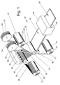
- FIG. 1 is an overall perspective and schematic view illustrating a first embodiment of a method of producing, in accordance with the teachings of the present invention, a membrane including two edgewise positioned reinforcing bands
- Fig. 2 is a view similar to the view of Fig. 1 of a second embodiment of the method according to the present invention of producing a membrane including two reinforcing bands
- Fig. 3 is a view similar to the view of Fig. 2 of a third embodiment of the method according to the present invention of producing a membrane including two reinforcing bands
- Fig. 4 is a view similar to the view of Fig.
- FIG. 5 is a view similar to the view of Fig. 4 of a fifth embodiment of the method according to the present invention of producing a membrane including two reinforcing bands
- Fig. 6 is a view similar to the view of Fig. 5 of a sixth embodiment of the method according to the present invention of producing a membrane including two reinforcing bands
- Fig. 7 is an overall perspective and schematic view illustrating an alternative technique of producing, in accordance with the teachings of the present invention, a membrane including two 'Keder' bands positioned edgewise along the membrane
- Fig. 5 is a view similar to the view of Fig. 4 of a fifth embodiment of the method according to the present invention of producing a membrane including two reinforcing bands
- Fig. 6 is a view similar to the view of Fig. 5 of a sixth embodiment of the method according to the present invention of producing a membrane including two reinforcing bands
- Fig. 7 is an overall perspective and schematic view illustrating an alternative technique of producing, in accordance with the teachings of
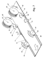
- FIG. 8 is a perspective and schematic view illustrating a step of cutting or separating the membrane into separate membrane segments
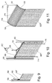
- Figs. 9, 10 and 11 are perspective, schematic and sectional views illustrating alternative techniques of using the membrane according to the present invention as a scaffold membrane
- Figs. 12a-14b are schematic and sectional views illustrating alternative techniques of producing a 'Keder' string of the membrane in accordance with the teachings of the present invention
- Figs. 15a-15d are perspective and schematic views illustrating details of alternative applications of the reinforcing bands of the membrane according to the teachings of the present invention allowing different fixation application and allowing folding of the membrane
- Figs. 16a-16e are schematic and partly sectional views illustrating various techniques of fixating a 'Keder' string relative to the composite foil assembly and/or different reinforcing structures positioned edgewise along the composite foil assembly.
- a process line is shown designated the reference numeral 10 in its entirety for carrying out a method according to the present invention of producing a membrane according to the present invention.
- the reference numerals 12 and 20 designate two plastic foils from which the composite or reinforced membrane is produced.
- the foils 12 and 20 constitute a bottom and top layer, respectively, of the final membrane and are delivered from two rolls 14 and 22, respectively.
- the rolls 14 and 22 are journalled on two axles 16 and 24, respectively.
- the two foils 12 and 20 are joint together by means of two pressure rollers 18 and 26, optionally constituted by heated rollers (heat embossing technique) for contacting the two foils 12 and 20 to one another.
- a fabric, mesh, grid or scrim 28 is delivered from a fabric, grid, mesh or scrim supply or roll 30, a fabric, mesh, grid or scrim 28 is delivered.
- the roll 30 is journalled on an axle 32 and the fabric, mesh, grid or scrim 28 is passed round a supporting roller 34 for allowing a lubricating oil or wax to be sprayed on to the fibres of the fabric, grid, mesh or scrim 28.
- the lubricating oil or wax is designated the reference numeral 40 and is delivered from dies 38 from a container 36, preferably a heated container, in which the lubricating oil or wax is contained.
- the technique of applying the lubrication oil or wax to the mesh or grid 28 is optional as according to the technique of producing a membrane according to the present invention may comprise the technique of applying the lubricating oil or wax or may be implemented without applying the lubricating oil or wax.
- the elements 36, 38 and 40 are consequently omitted.
- two 'Keder' bands 52 and 54 are delivered to the two pressure rollers 18 and 26.
- the rolls 56 and 58 are journalled on axles 60 and 62, respectively.
- the two 'Keder' bands 52 and 56 are edgewise sandwiched between the two foils 12 and 20 and are like the grid or mesh 28 laminated to the foils 12 and 20 by means of the rollers 18 and 26 for providing an integral structure in which the mesh 28 is laminated between the two foils 12 and 20 and likewise the bands 52 and 54 are laminated between the foils 12 and 20.
- the foils 12 and 20 may be constituted by any appropriate, preferably weather resistant plastics material, such as a PE, preferably LDPE or MDPE; LLDPE; VLDPE, alternatively termed plastomers; EVA; EBA; EMA; EAA; PP, preferably isotactic polypropylene homopolymer; random copolymers of propylene and ethylene, alternatively termed raco-PP; copolymers of propylene, ethylene and optionally higher alpha-olefins such as heterophasic block polymers, TPO; Polybutylene (Poly(1-butene)); block copolymers; crosslinked polymers such as EPDM, SBR, EPR, PIB, PEX, PIP, polyisobutylene and TPU; Plasticized PVC ; and blends or mixtures of any of the above, optionally having a bimodal molecular weight distribution, being block copolymers or combinations of block and copolymers.
- a PE preferably
- the fibres of the mesh or grid 28 may be constituted by any relevant fibre, filament or wire material which is compatible with the foil materials of the foils 12 and 20 and which are further compatible with the lubricating oil or wax 40.
- relevant materials are polypropylene, preferably isotactic polypropylene, polyethylene, preferably high density polyethylene, polyester or polyesters, preferably PET, polyamide or polyamides, polyacrylonitrile or polyurethane or polyurethanes, glass fibres or a combination of the above materials.
- the reinforcing fabric, grid, mesh or scrim may be made from polymer fibre, filament or wire material of a thickness of 0.1 - 1 mm, preferably 0.1 - 0.4 mm or of a thickness of 0.1 - 0.15 mm, 0.15 - 0.2 mm, 0.2 - 0.25 mm, 0.25 - 0.3 mm, 0.3 - 0.35 mm, 0.35 - 0.4 mm, 0.4 - 0.45 mm, 0.45 - 0.5 mm, 0.5 - 0.55 mm, 0.55 - 0.6 mm, 0.6 - 0.65 mm, 0.65 - 0.7 mm, 0.7 - 0.75 mm, 0.75 - 0.8 mm, 0.8 - 0.85 mm, 0.85 - 0.9 mm, 0.9 - 0.95 mm, 0.95 - 1 mm, and/or the reinforcing fabric, grid, mesh or scrim being made of polymer fibre, filament or wire material of a thickness of 300 - 4000 d
- 1000 - 3000 dtex preferably 1000 - 2500 dtex, or of a thickness of 300 - 600 dtex, 600 - 700 dtex, 700 - 800 dtex, 800 - 900 dtex, 900 - 1000 dtex, 1000 - 1250 dtex, 1250 - 1500 dtex, 1500 - 1750 dtex, 1750 - 2000 dtex, 2000 - 2500 dtex, 2500 - 3000 dtex, 3000 -3500 dtex or 3500 - 4000 dtex.
- the grid or mesh 28 may advantageously define a square or alternatively a rectangular mesh configuration defining a mesh size of the order of 2 - 40 mm, such as 4 - 12 mm, preferably 3 - 10 mm, such as approximately 10 mm, or a mesh size of the order of 2 - 3 mm, 3 - 5 mm, 5 - 7 mm, 7 - 9 mm, 9 - 11 mm, 11 - 13 mm, 13 - 15 mm, 15 - 20 mm, 20 - 25 mm, 25 -30 mm, 30 - 35 mm or 35 - 40 mm.
- the 'Keder' bands 52 and 54 may be made from any appropriate plastics material, preferably weather resistant plastics materials such as the above mentioned plastics materials, preferably a low frictional plastics material or a plastics material in which a surface coating of a low frictional material coating is provided or in which low frictional fibres or fabric be included.
- the 'Keder' bands 52 and 54 include, as will be well known in the art and as will be described in greater details below each a reinforcing string of a mechanically flexible polymer material such as a string of PVC or any other appropriate flexible elastomer or polymer material or a rope of nylon. Additional examples of relevant 'Keder' string materials are mentioned above in relation to the materials of the reinforcing fabric, grid, mesh or scrim.
- a composite sandwich 42 is produced which is input to a heating oven 44 in which the plastic materials of the foils 12 and 40 are softened for causing the two foils 12 and 20 to adhere to one another and for causing the 'Keder' bands 52 and 54 to be integrally joined to the foil 20.
- the resulting or final product is output from an output aperture 46 of the oven 44 and is shown in the right hand part of Fig. 1 and is designated the reference numeral 50.
- Fig. 2 the same process line 10 as illustrated in Fig. 1 is shown for sandwiching and laminating differently configurated pair of 'Keder' bands 51 and 53 relative to the sandwiching foils 12 and 20.
- the 'Keder' bands 52 and 54 shown in Fig. 1 were continuous bands having the 'Keder' strings encapsulated within the band constituting a continuous band
- the 'Keder' bands 51 and 53 are provided with apertures or perforations.
- One aperture or perforation of the 'Keder' band 51 is designated the reference numeral 55 and similarly, one aperture or perforation of the 'Keder' band 53 is designated the reference numeral 57.
- the apertures or perforations 55 and 57 serve the purpose of allowing the materials of the sandwiching foils 12 and 20 to be laminated together for establishing a bond between the two foils 12 and 20 through the apertures or perforations of the 'Keder' bands 51 and 53 apart from the integral joint between the materials of the foils 12 and 20 and the material of the sandwiched 'Keder' bands 51 and 53 in question.
- the apertures or perforations of the 'Keder' bands 51 and 53 are preferably rectangular, or of a square configuration or alternatively of a triangular or circular, elliptical or any other configuration. Provided the apertures or perforations are of a rectangular or square configuration, the apertures may have a length of 10 - 50 mm and a width of 10-30 mm.
- FIG. 3 an alternative embodiment of a process line for producing the membrane according to the present invention is shown designated the reference numeral 10' in its entirety.
- components or elements which have been described previously and are designated in the previous description a specific reference numeral, are in the description designated the same reference numeral as previously used and are only discussed or described in the context necessitated by the description itself.
- Components or elements differing from components or elements, respectively, described previously, still fulfilling the same purpose as a component or element previously described is designated the same reference integer, however added a marking for identifying the difference to the previously described component or element.
- the process line outlined in Fig. 3 basically differs from the above described process line 10 shown in Fig. 1 in that the softening oven 44 is omitted and the prefabricated foil 20 is substituted by a foil 25 which is readily extruded from an extruder 21 prior to the step of contacting the foil with the reinforcing grid or mesh 28, the 'Keder' bands 52 and 54 and the bottom foil 12 and which may be considered constituting a molden foil.
- an extruder 21 is shown including an extrusion die 23 from which the extruded foil 25 is delivered.
- the 'Keder' bands 52 and 54 are further in Fig.
- the foil 25 is, along with the reinforcing grid or mesh 28 and having the 'Keder' bands 52 and 54 positioned in contact with the top surface of the foil 25 and the bottom foil 12 input to a small gap between a pressure roller 17 which is pressed in the direction indicated by an arrow 19 into contact with a large diameter cooling roller 27 which is journalled on an axle 29.
- the grid or mesh 28 is passed round an additional roller 35 prior to introducing the grid or mesh into the gap between the prefabricated bottom foil 12 and the readily extruded foil 25. Similar to the process line described above with reference to Fig. 1, the elements 36, 38 and 40 for providing the lubrication of the mesh or grid 28 may be omitted.
- Fig. 3 the heating oven 44 is omitted and the final product delivered from the large diameter cooling roll 27 is passed round two rollers 31 and 33 before the finalised and cooled off membrane 50 is collected on a roll 37.
- Fig. 4 the process line 10' also shown in fig. 3 is illustrated for performing the alternative technique of sandwiching and laminating the perforated 'Keder' bands 51 and 53 also shown in Fig. 2 between the sandwiching foils 12 and 25 also shown in Fig. 3.
- a further alternative embodiment of a process line for producing the membrane according to the present invention is shown, designated the reference numeral 10" in its entirety.
- the process line outlined in Fig. 5 basically differs from the process line or process line 10' shown in Fig. 3 in that the bottom foil 12 is produced online by means of a further extruder 21' including an extrusion die 23' from which the extruded foil 25' is delivered.
- the extruded and softened foil 25' is passed round a cooling roller 27' which is journalled on an axle 29' from the cooling roller 27', a soft, yet partly solidified foil constituting the bottom foil 12 is delivered to the gap between the pressure roller 17 and the large diameter cooling roller 27, also shown in Fig. 3.
- the process line 10" is modified like the process line 10 is modified in Fig. 2 and the process line 10' is modified in Fig. 4 relative to the technique shown in Figs. 1 and 3, respectively, for laminating the perforated 'Keder' bands 51 and 53 between the two foils 25 and 25'.
- Fig. 7 an alternative technique is shown of producing the membrane including the 'Keder' bands laminated to the basic membrane in the process of producing the laminated basic membrane or after the lamination process.
- the basic membrane 42 is shown after the application of the two sandwiching foil layers 12 and 20 together as described above with reference to Figs. 1-6 and also in applicant's above mentioned published international patent application.
- two strings or ropes of flexible polymer material are applied edgewise to the foil assembly as two strings 61 and 63 are delivered from two string supplies or rolls 56' and 58' which are journalled on axles 60' and 62', respectively.
- the strings 61 and 63 are preferably nylon strings or similar flexible material.
- the strings are properly positioned along the edges of the foil assembly 42 by means of two rollers 64 and 66, respectively, having central recesses 68 and 70 serving the purpose of guiding the strings 61 and 63, respectively, into the intentional position offset inwardly relative to the outer edges of the foil assembly 42.
- additional rollers constituting counter rollers may be provided below the rollers 64 and 66, and further below the rollers 80 and 82 for mechanically supporting the strings 61 and 63.
- two separator wheels 72 and 74 serve the purpose of separating an edge part of the top foil of the foil assembly from the lower or bottom foil and at the same time turn over the foil flap backwards onto the top surface of the foil assembly 42 for encasing the strings 61 and 63 within the material of the turned over foil flap.
- the turned over foil flap produced by the separator wheel 72 serving the purpose of encasing the string 61 is designated the reference numeral 76 and similarly the turned over foil flap produced by means of the separator wheel is designated the reference numeral 78.
- two major rollers 80 and 82 similar to the rollers 64 and 66, respectively, and journalled on axles 84 and 86, respectively, serve the purpose of pressing the turned over flaps 76 and 78, respectively, into facial contact with the top surface of the foil assembly 42 and at the same time maintaining the strings 61 and 63 respectively within the intentional position encased within the turned over flaps 76 and 78, respectively, by means of central recesses 88 and 90 similar to the recesses 68 and 70, respectively.
- the final assembly having integrally included 'Keder' strings produced by the flexible polymer strings 61 and 63, 76 and 78, respectively, is moved to the heating oven 44 for heating the laminated assembly.
- the process line shown in Fig. 7 may further be modified by the addition of supplementary components such as heat blowers positioned between the separator wheels 72 and 74 and the rollers 80 and 82, respectively, for applying heat to the gap between the turned over flaps 76 and 78 and the underlying foil material.
- supplementary components such as heat blowers positioned between the separator wheels 72 and 74 and the rollers 80 and 82, respectively, for applying heat to the gap between the turned over flaps 76 and 78 and the underlying foil material.
- adhesive or glue applicators may be used as an alternative to or in conjunction with the heat blowers for providing an extrusion adhesion of the turned over flap 76 and 78, a fusion or melting of the turned over flaps to the underlying foil material.
- Alternative or supplementary techniques including fusion, adhesive, powder, hot-melt adhesion, ultrasonic or high frequency welding may further be employed.
- the overall orientation of transportation of the foil assembly 42 is indicated by a large arrow in the lower left hand part of the foil assembly 42, and the direction of rotation of the rollers and wheels 64, 66, 72, 74, 80 and 82 are indicated by individual arrows.
- the remaining edge part of the lower foil of the foil assembly 42 is prior to or after the heating in the heating oven 44 cut off so as to produce the final product having the 'Keder' bands positioned at the outermost edges of the band.
- the production step illustrated in Fig. 7 is performed as a separate step after the heating, in the heating oven 44, of the foil assembly produced according to the technique described in the applicant's above-identified published international patent application.
- the production technique may be further modified as illustrated in Fig. 8 as the foil having the integral 'Keder' bands, which foil is shown in Fig. 8 and designated the reference numeral 92 is then contacted with the reinforcing grid or mesh 28.
- the foil 92 includes, as is illustrated in Fig. 8, two edgewise positioned 'Keder' strings which are preferably produced according to the technique described in Fig. 7.
- the assembly of the foil 92 and the reinforcing grid or mesh 28 is cut into separate sections as is indicated schematically by a scissor 98 for the production of separate assembly sections one of which is designated the reference numeral 100.
- the step of cutting the assembly of the foil 92 and the reinforcing grid or mesh 28 into separate sections 100 may obviously be carried out after the finalising of the assembly and heating process or after the lamination of a top foil on to the reinforcing grid or mesh 28.
- FIGs. 9, 10 and 11 alternative techniques are shown of mounting an edgewise reinforced membrane according to the present invention in a mechanical guided structure.
- a membrane section 100' is shown having a top extension flap 102 by means of which pull the membrane section 100' may be pulled in a direction of an arrow 104 when guided in a profiled bar 106.
- eyelets 108 and 110 may be provided at the uppermost end of the membrane section 100" for receiving a transversal bar 112 which may be pulled upwardly by means of two ropes 114 and 166 or by means of a yoke part 118 in the direction of an arrow 120.
- the pulling of the membrane section 102 may be performed by means of a top turning bar or roll as is well known within the art per se.
- a further alternative of the technique of pulling the membrane section 100'" is shown as the membrane section 100"' is provided with two extension straps 124 and 126 which are fixated to a plurality of transversal bars serving as guiding bars and having the profile of the membrane section 100'" i.e. the profile of a central elongated bar and two cylindrical end bodies.
- One of the guiding bars is designated the reference numeral 128 and the cylindrical end bodies are designated the reference numerals 130 and 132.
- the top guiding bar may additionally be provided with rollers, wheels or similar journalling elements for reducing the friction during pulling the membrane section 100.
- the membrane section 100'" may be guided into its intentional and proper position by pulling the membrane section including the guiding bars by means of a rope, chain or similar pulling appliance as is illustrated in the right hand part of Fig. 11 along the direction of an arrow 134.
- the 'Keder' string is contemplated to be a conventional circular cylindrical string.
- the 'Keder' band may, however, be produced from a different element such as a profiled polymer band or a band including a non-circular cylindrical body or string.
- a band 140 is applied, which band is preferably made of a low frictional polymer material such as a woven or non-woven polymer material or a polymer foil including low frictional fibres or provided with a low frictional surface coating.
- the band 140 encases a string or body of a semicircular cylindrical configuration which body is designated the reference numeral 142.
- the band 140 extends beyond the outer edge of the foil assembly 42 and encases a further semicircular cylindrical string or body 144 similar to the body 142.
- the two semicircular cylindrical strings or bodies 142 and 144 together define a circular cylindrical 'Keder' string enclosed within the band 140 and positioned at the outer edge of the foil assembly 42.
- Figs. 12a and 12b may readily be employed in the process lines shown in Figs. 1-7 and used in integral lamination and heating technique as described above with reference to Figs. 1-6.
- an elliptical or any otherwise configurated 'Keder' body may produce, e.g. as illustrated in Fig. 13a in which the band 140 encases two non-semicircular cylindrical bodies 142' and 144' together providing, as illustrated in Fig. 13b, a transversal 'Keder' string body composed of the two bodies or parts 142' and 144'.
- 'Keder' bodies such as triangular, elliptical, polygonal or bodies combined from the semicircular cylindrical, triangular, polygonal or otherwise configurated elements may be readily produced employing the folding technique described above with reference to Figs. 12a, 12b, 13a and 13b.
- an additional 'Keder' element may be produced as is illustrated in Figs. 14a and 14b in which embodiment two semicircular cylindrical bodies 142 are positioned on the top surface of the composite foil 42 not shown in Figs. 14a and 14b, the left hand semicircular cylindrical body 142 providing a semicircular cylindrical 'Keder' string whereas the right hand semicircular cylindrical body 142 together with the semicircular cylindrical body 144 generate the circular cylindrical 'Keder' string as shown in Fig. 12b.
- the presence of the two semicircular bodies 142 makes it possible to modify the overall width of the composite membrane to the process of producing the membrane as the width of the composite membrane may be altered by contacting the semicircular cylindrical body 144 with the left-hand semicircular cylindrical body 142 and cutting off the outer free flap of the band 140.
- edge reinforced membrane may also be employed for producing differently configurated edge reinforcements such as providing an edge band 52"' to which a plurality of zipper bodies 146 may be fixated for generating a membrane according to the present invention having edgewise mounted zipper bodies for co-operating with similar fastening elements of the supporting structure to which the membrane is to be fixated.
- burr-like fixtures may be applied along the reinforcing band 52"' instead of the zipper bodies 146.
- a further modification of the 'Keder' string is illustrated as the 'Keder' string which in the above described embodiment has been described as a continuous string may be separated into minor segments such as a plurality of segments 61' shown in Fig. 15b which may be fixated within the turned over foil flap 76 or alternatively as illustrated in Fig. 15d be contained within the outer foil cover 148 allowing the 'Keder' string to be folded as is illustrated in Fig, 15d.
- Typical dimensions of the segmented 'Keder' string are: the diameter of the string being of the order 8 - 12 mm, the length of each segment being of the order of 20 - 50 cm, and the spacing between any two adjacent string segments being of the order of 10 - 25 mm.
- Fig. 16a a schematic view is shown illustrating a technique of fixating in the online production process shown in Figs. 1-6 of fixating a pre-cast 'keder' string enclosing band 150 to the foil assembly 42 which band encases the 'Keder' string 61 IV .
- the 'Keder' string 61 IV may be lubricated with an oil or wax for allowing the string to be freely movable within the band encasing produced by the pre-cast foil 150.
- the pre-cast band structure is further modified for providing sandwiching of the foil assembly 42 as the pre-cast band 150 is positioned having two surface parts adhered or laminated to opposite sides of the foil assembly 42.
- the sandwiching technique illustrated in Fig. 16b is further modified by the provision of the 'Keder' band 150 as a profiled structure in which the string 61 IV is pre-encased within a circumferentially encircling end part of the band 150.
- the reinforcing bands 52 V and 54 V may be used for supporting additonal flap elements extending outwardly from the reinforcing band 52 V and 54 V and designated the reference numerals 152 and 154, respectively.
- the elements 152 and 154 may constitute rigid or stiff flap elements or loops produced of woven filament ropes or any other mechanical fixture element which is welded or adhered in a lamination and/or heating process to the edge reinforcing bands 52 V and 54 V .
- a modified version of the pre-fabricated 'Keder' string encasing band 150 is shown designated the reference numeral 150' as the structure shown in Fig. 16f differs from the above described structure shown in Fig. 16a in that the encasing foil is provided with a weakening line extending longitudinal centrally within the band for controlling the folding of the band into the 'Keder' string encasing structure.
- the 'Keder' band 150 shown in Fig. 16 a is modified into the laminate structure produced according to the technique illustrated in Figs. 1, 3 or 5 as the band 150 is sandwiched between the two foils 12 and 20 of the foil assembly 42.
- a further alternative technique of fixating the 'Keder' band 150 relative to the foil assembly 42 is shown as the 'Keder' band 150 is fixated to the foil assembly 42 by means of co-operating burr fixtures 156.
- roller is shown schematically in which roller the function of laminating the foils 12 and 20 together and at the same time guiding the 'Keder' bands into their intentional edgewise position is shown, which roller is designated the reference numeral 26' and is to be understood as a schematic views exaggerating the outer peripheral recesses and clearly presenting a far too small width.
- a continuous composite membrane was made from the following components:
- the foil 12 was a 80 ⁇ m LDPE foil including flame retardents
- the mesh 28 was a 8 x 8 mm mesh size PET mesh of 1670 dtex multifilament yarn
- the top foil or coating layer 25 was a 120 ⁇ m LDPE foil including flame retardents.
- the 'Keder' band 52 and 54 were constituted by 200 mm width HDPE woven bands applied to the top surface of the coating layer or top foil 25.
- the 200 mm HDPE woven bands were turned over and were adhered to the respective band enclosing a 8 mm plastisized PVC 'Keder' string.
- the width of the composite membrane was 2,57 m and in the alternative variant, the width was 3,0 m.
- a pre-fabricated 'Keder' web made from woven PE fabric and including a 8,5 mm plastisized PVC string is laminated to the top foil or coating layer 25 in the process illustrated in Fig. 3 while employing the roller 26' shown in Fig. 17 and the foil 12, the mesh 28 and the top foil or coating layer 25 as specified in Example 1 above.
- the foil 12 is constituted by a 250 ⁇ m PE foil including frame retardants
- the mesh 28 is the mesh of Example 1 above without lubrication
- the top foil or coating layer 25 is a 250 ⁇ m PE foil.
- the 'Keder' bands 52 and 54 are constituted by woven PE bands of a width of 100 mm having apertures measuring 20 x 25 mm. Like the above described Example 1, a 'Keder' string of plastisized PVC of a diameter of 8,5 mm is used.
Landscapes
- Engineering & Computer Science (AREA)
- Architecture (AREA)
- Life Sciences & Earth Sciences (AREA)
- Environmental Sciences (AREA)
- Materials Engineering (AREA)
- Soil Sciences (AREA)
- Chemical & Material Sciences (AREA)
- Textile Engineering (AREA)
- Civil Engineering (AREA)
- Structural Engineering (AREA)
- Laminated Bodies (AREA)
- Tents Or Canopies (AREA)
- Separation Using Semi-Permeable Membranes (AREA)
Priority Applications (6)
| Application Number | Priority Date | Filing Date | Title |
|---|---|---|---|
| EP20030388083 EP1541337A1 (fr) | 2003-12-01 | 2003-12-01 | Membrane et son procédé de fabrication |
| US11/000,125 US20050170720A1 (en) | 2003-12-01 | 2004-11-30 | Membrane and a method of producing a membrane |
| NO20045268A NO20045268L (no) | 2003-12-01 | 2004-12-01 | Membran og fremgangsmate for a fremstille en membran |
| DE200460006360 DE602004006360T2 (de) | 2003-12-01 | 2004-12-01 | Membran und Verfahren zu deren Herstellung |
| AT04388086T ATE361832T1 (de) | 2003-12-01 | 2004-12-01 | Membran und verfahren zu deren herstellung |
| EP04388086A EP1541338B1 (fr) | 2003-12-01 | 2004-12-01 | Membrane et son procédé de fabrication |
Applications Claiming Priority (1)
| Application Number | Priority Date | Filing Date | Title |
|---|---|---|---|
| EP20030388083 EP1541337A1 (fr) | 2003-12-01 | 2003-12-01 | Membrane et son procédé de fabrication |
Publications (1)
| Publication Number | Publication Date |
|---|---|
| EP1541337A1 true EP1541337A1 (fr) | 2005-06-15 |
Family
ID=34486526
Family Applications (1)
| Application Number | Title | Priority Date | Filing Date |
|---|---|---|---|
| EP20030388083 Withdrawn EP1541337A1 (fr) | 2003-12-01 | 2003-12-01 | Membrane et son procédé de fabrication |
Country Status (5)
| Country | Link |
|---|---|
| US (1) | US20050170720A1 (fr) |
| EP (1) | EP1541337A1 (fr) |
| AT (1) | ATE361832T1 (fr) |
| DE (1) | DE602004006360T2 (fr) |
| NO (1) | NO20045268L (fr) |
Cited By (11)
| Publication number | Priority date | Publication date | Assignee | Title |
|---|---|---|---|---|
| WO2007000646A1 (fr) * | 2005-06-27 | 2007-01-04 | Bruce Simon Van Halderen | Materiau et joint pour un abri |
| WO2008082550A1 (fr) * | 2006-12-30 | 2008-07-10 | Owens Corning Intellectual Capital, Llc | Membrane de toiture plissée et système de bardeaux de toiture |
| WO2009152682A1 (fr) * | 2008-06-20 | 2009-12-23 | Jiang Jianming | Panneau en plastique comportant une grille de fibres et son procédé de préparation |
| US7641964B2 (en) | 2006-08-03 | 2010-01-05 | Saint-Gobain Performance Pastics Corporation | Roofing membrane |
| US7776446B2 (en) | 2001-06-04 | 2010-08-17 | Saint-Gobain Performance Plastics Corporation | Multi-layer release films |
| US7776428B2 (en) | 2006-02-13 | 2010-08-17 | Saint-Gobain Performance Plastics Corporation | Multi-layer release films |
| WO2012072426A1 (fr) * | 2010-11-29 | 2012-06-07 | Basell Poliolefine Italia S.R.L. | Membranes |
| US8726611B2 (en) | 2008-12-30 | 2014-05-20 | Saint-Gobain Performance Plastics Corporation | Method of installing a roofing membrane |
| CN104428130A (zh) * | 2012-07-06 | 2015-03-18 | 凡世通建筑产品公司 | 包含带有异氰酸酯反应性官能团的聚合物的热塑性膜 |
| CN106879395A (zh) * | 2016-12-27 | 2017-06-23 | 常熟市辛庄镇双浜梨业种植专业合作社 | 一种易于清洁的大棚用膜 |
| WO2018144364A1 (fr) * | 2017-02-03 | 2018-08-09 | Microsoft Technology Licensing, Llc | Panneau composite de faible masse volumique |
Families Citing this family (37)
| Publication number | Priority date | Publication date | Assignee | Title |
|---|---|---|---|---|
| DE102005019669A1 (de) * | 2005-02-08 | 2006-10-12 | Röhm Gmbh | Folienmembran mit hervorragender Witterungsbeständigkeit, hoher Durchlässigkeit für solare Wärmestrahlung, effektiver Zurückhaltung der von der Erde emittierten Wärmestrahlung und hoher mechanischer Festigkeit sowie Verfahren zur Herstelung der Folienmembran |
| US20060292945A1 (en) * | 2005-06-28 | 2006-12-28 | Building Materials Investment Corporation | Alternate/reduced scrim for single ply roofing membrane |
| WO2007027602A1 (fr) * | 2005-08-29 | 2007-03-08 | Bfs Diversified Products, Llc | Membranes de couverture thermoplastiques |
| DE102005046902A1 (de) * | 2005-09-30 | 2007-04-05 | Voith Patent Gmbh | Papiermaschinenbespannung |
| US20090181216A1 (en) * | 2006-02-17 | 2009-07-16 | Peng Lichih R | Roofing Membranes Including Fluoropolymer |
| US7882671B2 (en) * | 2006-02-21 | 2011-02-08 | Bfs Diversified Products, Llc | Multi-layer co-extruded roofing membrane |
| US20090269565A1 (en) * | 2006-05-18 | 2009-10-29 | Richard Peng | Polymeric laminates including nanoclay |
| US20070278846A1 (en) * | 2006-06-02 | 2007-12-06 | Fleming Vance S | Tire sidewall protecting cover |
| US9453322B2 (en) | 2006-09-25 | 2016-09-27 | J & S Franklin, Ltd. | Cellular confinement systems |
| GB0804487D0 (en) | 2008-03-11 | 2008-04-16 | Terram Ltd | Cellular structures |
| US20090250675A1 (en) * | 2008-03-24 | 2009-10-08 | Arthur Henry Cashin | Vehicle Barrier |
| US20090235814A1 (en) * | 2008-03-24 | 2009-09-24 | Cashin Arthur H | Mobile Reconfigurable Barricade |
| US20090235507A1 (en) * | 2008-03-24 | 2009-09-24 | Arthur Henry Cashin | Method Of Repairing A Ballistics Barrier |
| NL1036008C (nl) * | 2008-10-02 | 2010-04-06 | Willem-Paul Van Der Burg | Dockshelterflap, dockshelter voorzien van een dergelijke flap en werkwijze voor het vervaardigen van een dergelijke flap. |
| US9982437B2 (en) | 2009-02-24 | 2018-05-29 | Primesource Building Products, Inc. | Patterned roofing underlayment |
| US20110173908A1 (en) * | 2010-01-15 | 2011-07-21 | SE2 International LLC | Method and Apparatus for Reducing Solar Radiation Absorption Through a Roof |
| NZ610651A (en) * | 2010-10-25 | 2015-01-30 | Price Link Pty Ltd | Construction safety netting |
| GB2493007B (en) | 2011-07-21 | 2017-08-30 | Fiberweb Holdings Ltd | Confinement structures for particulate fill materials |
| DE102011053626A1 (de) * | 2011-09-15 | 2013-03-21 | Huesker Synthetic Gmbh | Lichtfirst, Materialkombination sowie Verfahren zur Eindeckung eines Lichtfirsts |
| FR2980136B1 (fr) * | 2011-09-21 | 2014-06-06 | Porcher Ind | Composites, leur procede de preparation et les voiles de vol les comprenant |
| US9790406B2 (en) | 2011-10-17 | 2017-10-17 | Berry Plastics Corporation | Impact-resistant film |
| WO2013106121A2 (fr) * | 2011-10-17 | 2013-07-18 | Berry Plastics Corporation | Film retardateur de flamme renforcé pour une protection de résistance à l'explosion |
| US10077565B2 (en) | 2012-06-05 | 2018-09-18 | Primesource Building Products, Inc. | Edge overlay for layered insulative blanket |
| WO2015024928A1 (fr) * | 2013-08-22 | 2015-02-26 | Aquaconsult Anlagenbau Gmbh | Dispositif d'aération et élément de recouvrement de protection contre les uv associé |
| JP2017106182A (ja) * | 2015-12-07 | 2017-06-15 | 大成建設株式会社 | カーボンメッシュ補強膜構造体 |
| AU2016200398B2 (en) * | 2016-01-22 | 2017-08-31 | System Stormseal Pty Ltd | Heat Shrink Covering of Built Structures and Method |
| WO2018053088A1 (fr) * | 2016-09-14 | 2018-03-22 | Tensar International Corporation | Système de protection des mers et des rivières et procédé de support de structures côtières |
| DE102017001818A1 (de) | 2017-02-27 | 2018-08-30 | K.L. Kaschier- Und Laminier Gmbh | Verkleidungsplatte für Baugerüste und Bauabtrennungen |
| US11032981B2 (en) * | 2017-05-22 | 2021-06-15 | Reach Supplies, Llc | Tree protection system |
| EP3987130B1 (fr) * | 2019-06-19 | 2024-11-06 | Top Greenhouses Ltd. | Couverture déployable et rétractable |
| CA3162720A1 (fr) | 2019-11-26 | 2021-06-03 | Bmic Llc | Panneaux de toiture a elements de deversement d'eau |
| WO2021252434A1 (fr) | 2020-06-08 | 2021-12-16 | Building Materials Investment Corporation | Membranes d'emballage de protection en tant que couche intégrée dans des composants de système de construction |
| DE102020115833A1 (de) * | 2020-06-16 | 2021-12-16 | Webasto SE | Verfahren zur Herstellung eines faltbaren Funktionselements eines Kraftfahrzeugs sowie Funktionselement mit einem Randkeder |
| US11866940B2 (en) | 2021-02-10 | 2024-01-09 | Bmic Llc | Roofing systems utilizing embedded decorative layer |
| US11608640B2 (en) | 2021-05-25 | 2023-03-21 | Bmic Llc | Panelized roofing system |
| US12397985B2 (en) | 2022-04-08 | 2025-08-26 | Odyssey Logistics And Technology Corporation | Outer cover for a flexible tank and optimized flexible tank for a 40 foot shipping container without a bulkhead |
| CN116100837B (zh) * | 2023-02-17 | 2025-05-30 | 新疆荣澳防水建材有限公司 | 一种耐高温复合防水卷材制备工艺 |
Citations (4)
| Publication number | Priority date | Publication date | Assignee | Title |
|---|---|---|---|---|
| EP0267590A1 (fr) * | 1986-11-10 | 1988-05-18 | Theis Gmbh | Bâches pour toit et parois de tentes de fêtes, tentes de hall ou similaires |
| US6093469A (en) * | 1998-08-25 | 2000-07-25 | Callas; Michael T. | Mat and method of making mat |
| WO2002075071A1 (fr) * | 2001-03-21 | 2002-09-26 | Icopal Plastic Membranes A/S | Membrane en particulier de protection contre les intemperies et procede de production d'une membrane, en particulier impermeable |
| US6564513B2 (en) * | 2000-02-16 | 2003-05-20 | Cover-All Building Systems, Inc. | Extrusion design and fabric installation method for weather tight seal |
Family Cites Families (7)
| Publication number | Priority date | Publication date | Assignee | Title |
|---|---|---|---|---|
| US1470138A (en) * | 1919-02-24 | 1923-10-09 | Blumenthal Maurice | Tire wrapper |
| US3455770A (en) * | 1965-04-13 | 1969-07-15 | Ernest A Dahl Jr | Magnetic index cards and method for producing same |
| NL185558C (nl) * | 1977-09-01 | 1990-05-16 | Nicolon Nv | Dekzeil. |
| US4698109A (en) * | 1984-05-03 | 1987-10-06 | Cantar Corporation | Method of making floatable sheet material |
| IE57079B1 (en) * | 1984-09-03 | 1992-04-22 | Kaysersberg Emballages Sa | Laminated web |
| US5746879A (en) * | 1994-04-13 | 1998-05-05 | Plascore, Inc. | Apparatus for making honeycomb from substrates and node strips |
| US20050103456A1 (en) * | 2003-10-24 | 2005-05-19 | Sca Hygiene Products Gmbh | Apparatus and method for embossing a multi-ply paper product |
-
2003
- 2003-12-01 EP EP20030388083 patent/EP1541337A1/fr not_active Withdrawn
-
2004
- 2004-11-30 US US11/000,125 patent/US20050170720A1/en not_active Abandoned
- 2004-12-01 NO NO20045268A patent/NO20045268L/no not_active Application Discontinuation
- 2004-12-01 DE DE200460006360 patent/DE602004006360T2/de not_active Expired - Lifetime
- 2004-12-01 AT AT04388086T patent/ATE361832T1/de not_active IP Right Cessation
Patent Citations (4)
| Publication number | Priority date | Publication date | Assignee | Title |
|---|---|---|---|---|
| EP0267590A1 (fr) * | 1986-11-10 | 1988-05-18 | Theis Gmbh | Bâches pour toit et parois de tentes de fêtes, tentes de hall ou similaires |
| US6093469A (en) * | 1998-08-25 | 2000-07-25 | Callas; Michael T. | Mat and method of making mat |
| US6564513B2 (en) * | 2000-02-16 | 2003-05-20 | Cover-All Building Systems, Inc. | Extrusion design and fabric installation method for weather tight seal |
| WO2002075071A1 (fr) * | 2001-03-21 | 2002-09-26 | Icopal Plastic Membranes A/S | Membrane en particulier de protection contre les intemperies et procede de production d'une membrane, en particulier impermeable |
Cited By (13)
| Publication number | Priority date | Publication date | Assignee | Title |
|---|---|---|---|---|
| US7776446B2 (en) | 2001-06-04 | 2010-08-17 | Saint-Gobain Performance Plastics Corporation | Multi-layer release films |
| WO2007000646A1 (fr) * | 2005-06-27 | 2007-01-04 | Bruce Simon Van Halderen | Materiau et joint pour un abri |
| US7776428B2 (en) | 2006-02-13 | 2010-08-17 | Saint-Gobain Performance Plastics Corporation | Multi-layer release films |
| US7641964B2 (en) | 2006-08-03 | 2010-01-05 | Saint-Gobain Performance Pastics Corporation | Roofing membrane |
| US7765763B2 (en) | 2006-12-30 | 2010-08-03 | Owens Corning Intellectual Capital, Llc | Pleated roofing membrane and roofing shingle system |
| WO2008082550A1 (fr) * | 2006-12-30 | 2008-07-10 | Owens Corning Intellectual Capital, Llc | Membrane de toiture plissée et système de bardeaux de toiture |
| WO2009152682A1 (fr) * | 2008-06-20 | 2009-12-23 | Jiang Jianming | Panneau en plastique comportant une grille de fibres et son procédé de préparation |
| US8726611B2 (en) | 2008-12-30 | 2014-05-20 | Saint-Gobain Performance Plastics Corporation | Method of installing a roofing membrane |
| WO2012072426A1 (fr) * | 2010-11-29 | 2012-06-07 | Basell Poliolefine Italia S.R.L. | Membranes |
| CN103228443A (zh) * | 2010-11-29 | 2013-07-31 | 巴塞尔聚烯烃意大利有限责任公司 | 膜 |
| CN104428130A (zh) * | 2012-07-06 | 2015-03-18 | 凡世通建筑产品公司 | 包含带有异氰酸酯反应性官能团的聚合物的热塑性膜 |
| CN106879395A (zh) * | 2016-12-27 | 2017-06-23 | 常熟市辛庄镇双浜梨业种植专业合作社 | 一种易于清洁的大棚用膜 |
| WO2018144364A1 (fr) * | 2017-02-03 | 2018-08-09 | Microsoft Technology Licensing, Llc | Panneau composite de faible masse volumique |
Also Published As
| Publication number | Publication date |
|---|---|
| ATE361832T1 (de) | 2007-06-15 |
| DE602004006360T2 (de) | 2008-01-10 |
| US20050170720A1 (en) | 2005-08-04 |
| DE602004006360D1 (de) | 2007-06-21 |
| NO20045268L (no) | 2005-06-02 |
Similar Documents
| Publication | Publication Date | Title |
|---|---|---|
| EP1541337A1 (fr) | Membrane et son procédé de fabrication | |
| EP1541338B1 (fr) | Membrane et son procédé de fabrication | |
| US5773373A (en) | Reinforced laminate with elastomeric tie layer | |
| EP1243716B1 (fr) | Membrane, en particulier membrane d'étanchéité et sa méthode de fabrication | |
| US7309665B2 (en) | Failure resistant flame retardant vapor barrier insulation facing | |
| US20170183873A1 (en) | Antislip sheet material having tapes and monofilaments | |
| MX2008015097A (es) | Material compuesto de construccion de edificio que tiene una o mas capas de lienzo de refuerzo. | |
| US20090025873A1 (en) | Impack Resistant Composite Building Panel | |
| US20140072751A1 (en) | Waterproof membranes | |
| WO2009143432A2 (fr) | Membranes de toiture | |
| CA2620190A1 (fr) | Systeme de couverture ignifuge | |
| KR101343990B1 (ko) | 자기점착식 지붕재 시트 및 그의 제조방법 | |
| US11939773B2 (en) | Roofing composites with integrated selvage edges | |
| US11840841B2 (en) | Self-sealing construction material | |
| MX2007001174A (es) | Laminados de construccion. | |
| US20170326835A1 (en) | Breathable laminate housewrap and underlayment | |
| US12553242B2 (en) | Roofing membrane with protective film | |
| WO2002018692A2 (fr) | Tissu multi-axial pour l'exterieur, resistant aux intemperies | |
| US20210060911A1 (en) | Lightweight underlayment | |
| JP3340023B2 (ja) | 建築・土木用複合防水シート | |
| US12024819B2 (en) | Composite structures and methods of preparation | |
| EP1183152A1 (fr) | Tissu composite et son utilisation | |
| JP5009185B2 (ja) | 難燃性積層加工布及びその難燃性積層加工布の製造方法 | |
| CN210238952U (zh) | 一种复合纤维增强型双面粘防水卷材 | |
| KR101713624B1 (ko) | 자착식 노출 복합시트 |
Legal Events
| Date | Code | Title | Description |
|---|---|---|---|
| PUAI | Public reference made under article 153(3) epc to a published international application that has entered the european phase |
Free format text: ORIGINAL CODE: 0009012 |
|
| AK | Designated contracting states |
Kind code of ref document: A1 Designated state(s): AT BE BG CH CY CZ DE DK EE ES FI FR GB GR HU IE IT LI LU MC NL PT RO SE SI SK TR |
|
| AX | Request for extension of the european patent |
Extension state: AL LT LV MK |
|
| STAA | Information on the status of an ep patent application or granted ep patent |
Free format text: STATUS: THE APPLICATION IS DEEMED TO BE WITHDRAWN |
|
| 18D | Application deemed to be withdrawn |
Effective date: 20050404 |