EP1541410A1 - Siège - Google Patents
Siège Download PDFInfo
- Publication number
- EP1541410A1 EP1541410A1 EP04027919A EP04027919A EP1541410A1 EP 1541410 A1 EP1541410 A1 EP 1541410A1 EP 04027919 A EP04027919 A EP 04027919A EP 04027919 A EP04027919 A EP 04027919A EP 1541410 A1 EP1541410 A1 EP 1541410A1
- Authority
- EP
- European Patent Office
- Prior art keywords
- tray
- seat cushion
- seat
- main part
- compartment
- Prior art date
- Legal status (The legal status is an assumption and is not a legal conclusion. Google has not performed a legal analysis and makes no representation as to the accuracy of the status listed.)
- Withdrawn
Links
- 235000013361 beverage Nutrition 0.000 claims description 10
- 238000009432 framing Methods 0.000 description 21
- 230000013011 mating Effects 0.000 description 4
- 230000005291 magnetic effect Effects 0.000 description 3
- 239000004033 plastic Substances 0.000 description 3
- 230000005294 ferromagnetic effect Effects 0.000 description 2
- 238000012986 modification Methods 0.000 description 2
- 230000004048 modification Effects 0.000 description 2
- 230000003014 reinforcing effect Effects 0.000 description 2
- 229910000831 Steel Inorganic materials 0.000 description 1
- 238000010586 diagram Methods 0.000 description 1
- 230000000694 effects Effects 0.000 description 1
- 238000000034 method Methods 0.000 description 1
- 239000010959 steel Substances 0.000 description 1
- 239000000126 substance Substances 0.000 description 1
- 229920003051 synthetic elastomer Polymers 0.000 description 1
- 229920003002 synthetic resin Polymers 0.000 description 1
- 239000000057 synthetic resin Substances 0.000 description 1
- 239000005061 synthetic rubber Substances 0.000 description 1
- 239000002699 waste material Substances 0.000 description 1
Images


Classifications
-
- B—PERFORMING OPERATIONS; TRANSPORTING
- B60—VEHICLES IN GENERAL
- B60N—SEATS SPECIALLY ADAPTED FOR VEHICLES; VEHICLE PASSENGER ACCOMMODATION NOT OTHERWISE PROVIDED FOR
- B60N3/00—Arrangements or adaptations of other passenger fittings, not otherwise provided for
- B60N3/08—Arrangements or adaptations of other passenger fittings, not otherwise provided for of receptacles for refuse, e.g. ash-trays
-
- B—PERFORMING OPERATIONS; TRANSPORTING
- B60—VEHICLES IN GENERAL
- B60N—SEATS SPECIALLY ADAPTED FOR VEHICLES; VEHICLE PASSENGER ACCOMMODATION NOT OTHERWISE PROVIDED FOR
- B60N2/00—Seats specially adapted for vehicles; Arrangement or mounting of seats in vehicles
- B60N2/24—Seats specially adapted for vehicles; Arrangement or mounting of seats in vehicles for particular purposes or particular vehicles
- B60N2/30—Non-dismountable or dismountable seats storable in a non-use position, e.g. foldable spare seats
- B60N2/3038—Cushion movements
- B60N2/304—Cushion movements by rotation only
- B60N2/3045—Cushion movements by rotation only about transversal axis
- B60N2/305—Cushion movements by rotation only about transversal axis the cushion being hinged on the vehicle frame
-
- B—PERFORMING OPERATIONS; TRANSPORTING
- B60—VEHICLES IN GENERAL
- B60N—SEATS SPECIALLY ADAPTED FOR VEHICLES; VEHICLE PASSENGER ACCOMMODATION NOT OTHERWISE PROVIDED FOR
- B60N3/00—Arrangements or adaptations of other passenger fittings, not otherwise provided for
- B60N3/001—Arrangements or adaptations of other passenger fittings, not otherwise provided for of tables or trays
- B60N3/002—Arrangements or adaptations of other passenger fittings, not otherwise provided for of tables or trays of trays
-
- B—PERFORMING OPERATIONS; TRANSPORTING
- B60—VEHICLES IN GENERAL
- B60N—SEATS SPECIALLY ADAPTED FOR VEHICLES; VEHICLE PASSENGER ACCOMMODATION NOT OTHERWISE PROVIDED FOR
- B60N3/00—Arrangements or adaptations of other passenger fittings, not otherwise provided for
- B60N3/10—Arrangements or adaptations of other passenger fittings, not otherwise provided for of receptacles for food or beverages, e.g. refrigerated
- B60N3/102—Arrangements or adaptations of other passenger fittings, not otherwise provided for of receptacles for food or beverages, e.g. refrigerated storable or foldable in a non-use position
-
- B—PERFORMING OPERATIONS; TRANSPORTING
- B60—VEHICLES IN GENERAL
- B60R—VEHICLES, VEHICLE FITTINGS, OR VEHICLE PARTS, NOT OTHERWISE PROVIDED FOR
- B60R7/00—Stowing or holding appliances inside vehicle primarily intended for personal property smaller than suit-cases, e.g. travelling articles, or maps
- B60R7/04—Stowing or holding appliances inside vehicle primarily intended for personal property smaller than suit-cases, e.g. travelling articles, or maps in driver or passenger space, e.g. using racks
- B60R7/043—Stowing or holding appliances inside vehicle primarily intended for personal property smaller than suit-cases, e.g. travelling articles, or maps in driver or passenger space, e.g. using racks mounted on or under a seat
Definitions
- the present invention relates to a seat unit with a tray table provided on one side of a seat cushion for holding various kinds of articles.
- a prior art example of a seat unit of this kind is found in Japanese Unexamined Patent Publication No. 1995-315097, for instance, in which a tray table 101 is provided on one side of a seat cushion 100, on which a vehicle occupant is seated, for holding various articles, and the tray table 101 can be flipped down from a horizontal position shown in FIG. 25A to a vertically hanging storage position shown in FIG. 25B, and vice versa, as necessary.
- the aforementioned conventional tray table 101 is disposed on the side of the seat cushion 100 and can be folded down to the storage position to reduce overall width when not in use.
- This structure of the tray table 101 offers a certain degree of so-called walk-through capability by providing an extra space beside the seat cushion 100 to allow a passenger in a rear seat to move forward. Even when the tray table 101 has been shifted to the storage position, however, the vertically hanging tray table 101 remains on the side of the seat cushion 100, so that the tray table 101 in the storage position inevitably interferes with a moving passenger limiting internal walk-through access. From this point of view, there has been a room for improving the tray table structure.
- a seat unit equipped with a tray table which can be used for holding articles when necessary and can be stored when unnecessary so that the tray table would not interfere with internal walk-through access of a vehicle.
- a seat unit includes a seat cushion, a tray compartment located under the seat cushion, a tray which is made storable in the tray compartment, a seat cushion swing mechanism which makes it possible to expose the top side of the tray compartment by swinging up the seat cushion about a support shaft provided at one end of the seat cushion, and a tray support provided on a seat-side member for supporting the tray in such a manner that the tray can be moved between a storage position inside the tray compartment and a service position on one side of the seat cushion after swinging up the seat cushion.
- the tray supported by the tray support can be folded out to the service position located on one side of the seat cushion with the top side of the tray compartment exposed by swinging up the seat cushion about the support shaft provided at one end of the seat cushion so that the tray can be used as a platform for holding various articles when necessary.
- the tray can be stowed back to the storage position located under the seat cushion so that a free space is created on one side of the seat cushion to provide an improved walk-through capability for passengers.
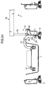
- FIG. 1 is a plan view generally showing the structure of a motor vehicle 30 equipped with first-row seats 31 at the front of a passenger compartment, second-row seats 32 located just behind the first-row seats 31, and a third-row seat 33 located just behind the second-row seats 32. While the first-row seats 31 and the second-row seats 32 are pairs of bucket seats separately installed on left and right sides of the first and second rows, respectively, the third-row seat 33 is a single bench-style seat. Among these seats, the second-row bucket seat 32 installed on the right side of the second row is a seat unit 1 according to a preferred embodiment of the invention.
- the seat unit 1 of the present embodiment includes a pair of left and right guide rails 2 firmly fixed to a floor of a vehicle body, a pair of left and right slide members 4 supported slidably along the guide rails 2, a seat cushion 3 mounted on the slide members 4 and a backrest 5 supported tiltably about a horizontal shaft (not shown) provided at rear ends of the slide members 4.
- a horizontally elongate support shaft 6 of a seat cushion swing mechanism 20 by which the seat cushion 3 is swingably supported. More specifically, a cushion frame (not shown) disposed below the seat cushion 3, for instance, is supported by the slide members 4 via the support shaft 6, and as the seat cushion 3 is swung, or lifted, up and down about the support shaft 6, the seat cushion 3 moves between an upright position at which a rear end of the seat cushion 3 is raised as illustrated by imaginary lines in FIG. 2 and a normal seating position at which the seat cushion 3 lies generally horizontally on the slide members 4.
- the seat unit 1 is equipped with a tray 10 for holding articles and a tray support 21 for supporting the tray 10.
- the tray support 21 includes a pair of front and rear brackets 23 attached to an inner side surface of the left-hand slide member 4 which is a seat-equipped mechanical member and a horizontal shaft 24 fitted between upper parts of the two brackets 23, and a later-described supporting frame 12 of the tray 10 is supported by the brackets 23 via the horizontal shaft 24.
- the tray support 21 is structured such that the tray 10 can be moved between a service position ⁇ at which the tray 10 sticks out sideways and a storage position ⁇ at which the tray 10 is stored in a tray compartment 7 located beneath the seat cushion 3 by swinging the tray 10 about the horizontal shaft 24 with the seat cushion 3 raised to the upright position as illustrated in FIG. 2.
- the tray 10 includes a tray main part 11 having a generally rectangular shape in top view made of synthetic resin, for example, and the aforementioned supporting frame 12 attached to the bottom of the tray main part 11.
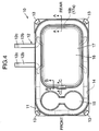
- the tray main part 11 has a generally rectangular outer framing portion 14 in which a downward opening groove is made on the bottom side, four hooks 13 extending upward from lower ends of four corners of the outer framing portion 14 and reinforcing ribs 14c formed in the groove in the outer framing portion 14 at specific intervals as shown in FIGS. 4 to 6.
- a recess 15 located on a front side serving as holders for beverage receptacles and a flat portion 16 located on a rear side for holding various articles.
- the tray main part 11 is shaped such that the flat portion 16 is located at a height lower than a top surface of the outer framing portion 14, forming a flat surface like that of a dish for holding articles.
- a generally rectangular through hole 16a of which size is a little smaller than the flat portion 16 in the tray main part 11, and the flat portion 16 is made by fitting a generally rectangular flat cover plate 17 to cover the through hole 16a.
- the recess 15 has a pair of left and right cylindrical holes in which lower parts of beverage receptacles are fitted and a joining channel interconnecting the left and right holes.
- the supporting frame 12 has a main portion 12a which is generally C-shaped in top view and a pair of front and rear arms 12b extending from both ends of the main portion 12a as shown in FIG. 5.
- the tray main part 11 is structured such that the main portion 12a of the supporting frame 12 can be fitted into the outer framing portion 14 of the tray main part 11 from the bottom side thereof.
- Each of the arms 12b of the supporting frame 12 has a vertical portion extending downward from one end of the main portion 12a and a horizontally projecting portion extending outward from a bottom end of the vertical portion, and there are formed shaft holes 12c in which the aforementioned horizontal shaft 24 is fitted near extreme ends of the horizontally projecting portions of the arms 12b.
- the hookup protrusions 14a formed on the outer framing portion 14 of the tray main part 11 fit into the mating holes 12d formed in the right-hand hollow straight section of the main portion 12a of the supporting frame 12.
- the fixing bolts 18 are tightened into the mating holes 12d formed in the left-hand hollow straight section of the main portion 12a of the supporting frame 12 as illustrated in FIG. 6, whereby the tray main part 11 is secured to the supporting frame 12.
- the hookup protrusions 14a and the fixing bolts 18 together constitute fixing parts.
- the supporting frame 12 is fitted with brackets 19 made of shaped wires for supporting the tray main part 11 with part of the bottom of the tray main part 11 located inside the supporting frame 12 lying on the wire frames 19.
- Each of these wire frames 19 has a pair of fixing parts located at both ends which are attached to the bottom of the main portion 12a of the supporting frame 12 and a generally horizontal central arm projecting inward from the main portion 12a.
- the tray main part 11 is supported by the wire frames 19 with the bottom of the tray main part 11 held in contact with the projecting arms of the wire frames 19.
- a net bag 25 having an upper opening serving as a utility storage container is provided underneath the tray 10.
- Upper edges of the net bag 25 along an opening 25a at the upper end of the net bag 25 are placed in the outer framing portion 14 of the tray main part 11 and clamped between the outer framing portion 14 and the supporting frame 12.
- the net bag 25 fitted to the tray 10 in this way hangs from the tray 10 as shown in FIG. 3. More specifically, the hookup protrusions 14a and the fixing bolts 18 together constituting the fixing parts are passed through meshes of the net bag 25 or hooking slits formed therein, whereby the upper opening 25a of the net bag 25 is fixed to the outer framing portion 14 of the tray main part 11.
- the height H1 of the net bag 25 constituting the utility storage container from the upper opening 25a to the bottom of the net bag 25 is made smaller than the height H2 of the tray compartment 7 from an upper end thereof to the opening 25a of the net bag 25 as measured when the tray 10 is retracted to its storage position ⁇ as shown in FIG. 3.
- a seat-side member 4a is fitted to the outside of the left-hand (right-hand as illustrated in FIG. 3) slide member 4 of the right-hand second-row seat 32, and a cushion pad 22 made of synthetic rubber, for example, is attached to a top surface of the seat-side member 4a.
- stepped ridges 16c projecting rearward from portions of the front side of the through hole 16a, and not from a middle portion thereof, and locking parts 17b formed on a front end of the cover plate 17 fit onto the stepped ridges 16c on the front side of the through hole 16a at the flat portion 16 of the tray main part 11 (refer to FIG. 8B).
- the cover plate 17 When the ridge 17a formed on the cover plate 17 is inserted into the slit 16b formed at the flat portion 16 of the tray main part 11 and the locking parts 17b of the cover plate 17 are mated with the stepped ridges 16c on the front side of the through hole 16a at the flat portion 16 of the tray main part 11, the cover plate 17 is locked in position closing the through hole 16a.
- a projection 16d at the bottom of the outer framing portion 14 of the tray main part 11 extending rearward from the middle of the front side of the through hole 16a with a cutout formed just above the projection 16d for creating a clearance S2 between the outer framing portion 14 and the front end of the cover plate 17.
- a hang-on part 17c extending flush with a top surface of the cover plate 17 from the middle of the front end thereof, the hang-on part 17c facing the projection 16d of the outer framing portion 14 with a clearance S1 in between.
- This arrangement makes it possible to easily lift the front end of the cover plate 17 with a fingertip inserted into a space created by the clearances S1 and S2 and remove the cover plate 17 upon releasing the locking parts 17b of the cover plate 17 from the stepped ridges 16c at the front side of the through hole 16a in the flat portion 16 of the tray main part 11.
- the structure of the embodiment includes the seat cushion 3, the tray compartment 7 provided underneath the seat cushion 3, the tray 10 storable in the tray compartment 7 and the seat cushion swing mechanism 20 which makes it possible to expose the top side of the tray compartment 7 by swinging up the seat cushion 3 about the support shaft 6 at one end of the seat cushion 3.
- the tray support 21 sustains the tray 10 in such a manner that the tray 10 can be moved between the service position ⁇ and the storage position ⁇ in the tray compartment 7 located under the seat cushion 3 under conditions where the top side of the tray compartment 7 is exposed with the seat cushion 3 swung up as shown by the imaginary lines in FIG. 2. Since this tray support 21 is attached to the seat-equipped mechanical member, or the left-hand slide member 4 of the seat unit 1 of FIG.
- the tray 10 can be pulled out to the service position ⁇ on the left side of the seat cushion 3 whenever it is desired to place articles on the tray 10.
- the tray 10 can be stowed back to the storage position ⁇ in the tray compartment 7 so that a free space is created on the left side of the seat cushion 3, thereby providing an improved walk-through capability for passengers.
- the structure of the aforementioned embodiment is provided with the utility storage container made of the net bag 25 which has an upper opening and hangs from the tray 10 when the tray 10 is set in the storage position ⁇ , the through hole 16a joining the upper opening of the net bag 25 to a space above the tray 10, and the cover plate 17 which covers or uncovers the through hole 16a.
- This arrangement of the embodiment makes it possible to place and take out articles in and from the net bag 25 through the through hole 16a upon lifting up the cover plate 17 when the tray 10 is in the service position ⁇ .
- This arrangement is also advantageous in that the cover plate 17 can be used as a platform for holding various articles when set in position to cover the through hole 16a.
- the recess 15 for holding beverage receptacles and the flat portion 16 for holding articles are located in separate areas and the flat portion 16 of the tray main part 11 is formed by the removable cover plate 17.
- This structure enables a passenger to place and take out articles in and from the net bag 25 upon lifting up the cover plate 17 without accidentally touching the beverage receptacles held in the recess 15 and spilling their contents.
- the structure of the embodiment also enables the passenger to easily place and remove the beverage receptacles in and from the recess 15 regardless of whether the cover plate 17 is set in position or not.
- the tray 10 includes the tray main part 11 having the recess 15 for holding beverage receptacles and the flat portion 16 for holding articles as well as the supporting frame 12 to which the tray main part 11 is fixed by means of the fixing parts including the hookup protrusions 14a and the fixing bolts 18, and the net bag 25 constituting the utility storage container is attached to the tray 10 by the aforementioned fixing parts.
- This structure of the embodiment is advantageous in that the net bag 25 constituting the utility storage container can be compactly stored in the tray compartment 7 with ease when it is not necessary to use the tray 10.
- the structure of the embodiment is also advantageous in that the tray main part 11 can be attached to the supporting frame 12 without the need for any dedicated fixtures and the utility storage container made of the net bag 25 can be attached to the tray 10 with a simple arrangement.
- the supporting frame 12 is fitted with the wire frames 19 for supporting the tray main part 11 located inside the supporting frame 12 in the foregoing embodiment.
- This arrangement is advantageous in that the stiffness of the supporting frame 12 can be effectively increased by a simple structure so that the supporting frame 12 can support the tray main part 11 in a stable manner
- the utility storage container is made of a pouchlike flexible container similar to the net bag 25 and the height H1 of the net bag 25 from the upper opening 25a to the bottom of the net bag 25 is made smaller than the height H2 of the tray compartment 7 from the upper end thereof to the opening 25a of the utility storage container (net bag 25) as measured when the tray 10 is retracted to its storage position ⁇ in the foregoing embodiment.
- This arrangement ensures that the bottom of the utility storage container would not project from the tray compartment 7 beyond the upper end thereof when the tray 10 is stowed in the tray compartment 7 with the utility storage container attached to the tray 10. Therefore, the arrangement serves to effectively prevent the bottom of the utility storage container from being caught between the top of the tray compartment 7 and the bottom of the seat cushion 3.
- the present embodiment may be modified such that the seat unit 1 employs, instead of the aforementioned arrangement in which the utility storage container made of the net bag 25 is attached to the tray 10 by means of the fixing parts including the hookup protrusions 14a and the fixing bolts 18, an arrangement in which an utility storage container made of a pouchlike flexible container is attached to the tray 10 by means of the hooks 13 formed on an outer periphery of the tray main part 11.
- a flexible container 26 such as a plastic shopping bag, may be suspended from the tray main part 11 to cover the bottom side of the tray 10 with hooking parts 26a of the flexible container 26 (handles of the shopping bag) provided at an upper end thereof hooked on the hooks 13 located at the four corners of the tray main part 11 as shown in FIG. 9.
- This alternative arrangement is advantageous in that a widely available shopping bag suspended from the tray 10 can be used as a waste disposal bag which can be easily removed whenever desired.
- the present embodiment may also be modified such that the seat unit 1 employs, instead of the aforementioned arrangement in which the single flexible container 26 is attached to the tray main part 11 to cover the bottom side of the tray 10, an arrangement in which two or more flexible containers 26, such as plastic shopping bags, are suspended from the front and rear of the tray 10 as shown in FIG. 10, for instance.
- the tray 10 has the through hole 16a joining the top and bottom sides of the tray 10 and the cover plate 17 which covers or uncovers the through hole 16a and the hooks 13 are formed on the outer periphery of the tray main part 11.
- This arrangement is advantageous in that widely available shopping bags or the like can be suspended from desired positions by attaching hooking parts (handles) 26a of the flexible containers 26 to the hooks 13 when necessary and easily removed.
- the location and the size of the through hole 16a are not limited to this structure of the embodiment but may be modified in various ways.
- the seat unit 1 may employ a structure in which a trough hole joining the top and bottom sides of the tray 10 is formed in part of the entire area of the flat portion 16 and a cover plate for covering and uncovering the trough hole is placed on the tray 10.
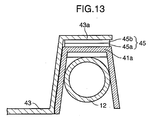
- FIGS. 11, 12 and 13 are diagrams showing a seat unit 1 according to another form of embodiment of the invention.
- the seat unit 1 of this embodiment is equipped with a tray 40 of which cover plate 43 provided at a flat portion 42 of a tray main part 41 can be opened and closed by means of a pair of hinges 44.
- a through hole 42a joining the top and bottom sides of the tray 40 except for a front part 42b of the flat portion 42 is formed in the flat portion 42 of the tray main part 41, and the cover plate 43 for covering and uncovering the through hole 42a is supported swingably about the hinges 44 located at a front end of the cover plate 43.
- the cover plate 43 has at its rear end a finger-operated tab 43a which lies on a rearmost end of an outer framing portion 41a of the tray main part 41 as well as a retainer 45 which is located between the finger-operated tab 43a and the outer framing portion 41a of the tray main part 41.
- the retainer 45 includes a permanent magnet 45a affixed to a top surface of the outer framing portion 41a of the tray main part 41 and a piece of ferromagnetic substance 45b, such as a flat steel bar, affixed to a bottom surface of the finger-operated tab 43a so that the cover plate 43 is normally held in its closed position by a magnetic force exerted by the permanent magnet 45a.
- the cover plate 43 can be moved to its upper open position by lifting the finger-operated tab 43a of the cover plate 43 from its closed position to release the ferromagnetic piece 45b from the permanent magnet 45a and swinging up the cover plate 43 about the hinges 44.
- the structure of this embodiment is advantageous in that when the tray 40 is set to its storage position ⁇ with the through hole 42a closed by the cover plate 43, the cover plate 43 is held in its closed position by the magnetic force exerted by the permanent magnet 45a.
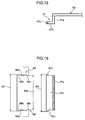
- the present embodiment may be modified such that the seat unit 1 employs, instead of the aforementioned arrangement in which the cover plate 43 is swingably supported by the hinges 44, an arrangement shown in FIG. 14 in which the cover plate 43 for covering and uncovering the through hole 42a in the tray main part 41 has a finger-operated part 46 formed at a free end (front end) of the cover plate 43 that is used when opening the cover plate 43 and a supporting tab 47 formed at a fixed end (rear end) of the cover plate 43 that serves as a pivot shaft about which the cover plate 43 is swung up and down, and a tab fitting part 48 is formed in the tray main part 41 such that the supporting tab 47 of the cover plate 43 can be detachably fitted to the tab fitting part 48 of the tray main part 41.
- the supporting tab 47 of the cover plate 43 has a vertical portion 47a extending downward from the fixed end of the cover plate 43, a horizontal portion 47b extending horizontally frontward from a lower end of the vertical portion 47a and a pair of hemispherical protrusions 47c formed on both left and right end surfaces of the horizontal portion 47b.
- the tab fitting part 48 formed in the tray main part 41 has a tab fitting opening 48a having a width corresponding to the width of the vertical portion 47a and the horizontal portion 47b of the supporting tab 47, a pair of left and right cut portions 48b formed at a rear end of the tab fitting opening 48a and a pair of left and right protruding stopper portions 48c jutting out inward from a front end of the tab fitting opening 48a.
- the distance W1 between the left and right cut portions 48b is made a little larger than the distance W0 between the left and right protrusions 47c
- the distance W2 between the left and right protruding stopper portions 48c is made a little smaller than the distance W0 between the two protrusions 47c.
- the cover plate 43 structured as explained above is fitted to the tray main part 41 as follows. After passing the protrusions 47c formed on the left and right end surfaces of the supporting tab 47 of the cover plate 43 downward between the cut portions 48b of the tab fitting part 48 of the tray main part 41 from above, the cover plate 43 is placed on the tray main part 41 as shown in FIG. 17 so that the cover plate 43 closes the through hole 42a in the tray main part 41. Then, the cover plate 43 is moved to its open position as shown in FIG. 18 by lifting and swinging the free end of the cover plate 43 with a fingertip hooked on the finger-operated part 46.
- the cover plate 43 can be removed from the tray main part 41 by lifting the cover plate 43 so that the protrusions 47c formed on the left and right end surfaces of the supporting tab 47 of the cover plate 43 pass through the tab fitting part 48 upward from below the tray main part 41 to a space above the through hole 42a reversing the aforementioned procedure used when fitting the cover plate 43.
- the aforementioned structure in which the supporting tab 47 of the cover plate 43 is detachably fitted into the tab fitting part 48 of the tray main part 41 is advantageous in that an entire area of the through hole 42a can be held open by removing the cover plate 43 from the tray main part 41 and storing the cover plate 43 in a specified location when the cover plate 43 is not necessary.
- the cover plate 43 can also be removed from the tray main part 41 by further turning the cover plate 43 in its opening direction from the open position shown in FIG. 18, causing the protruding stopper portions 48c of the tab fitting part 48 to elastically deform and the protrusions 47c of the supporting tab 47 to be released from the protruding stopper portions 48c, instead of lifting the cover plate 43 upward as discussed above.
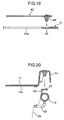
- the present embodiment may also be modified such that the seat unit 1 employs, instead of the aforementioned arrangement (FIG. 13) in which the cover plate 43 is held in the closed position by the magnetic force exerted by the permanent magnet 45a, an arrangement in which the cover plate 43 is fitted with a snap-in clip 49 located near the free end of the cover plate 43 and detachably locked in the closed position by forcing the snap-in clip 49 into a retaining hole 50 formed in the tray main part 41 as shown in FIG. 19.
- the seat unit 1 employs, instead of the aforementioned arrangement (FIG. 13) in which the cover plate 43 is held in the closed position by the magnetic force exerted by the permanent magnet 45a, an arrangement in which the cover plate 43 is fitted with a snap-in clip 49 located near the free end of the cover plate 43 and detachably locked in the closed position by forcing the snap-in clip 49 into a retaining hole 50 formed in the tray main part 41 as shown in FIG. 19.
- the seat unit 1 employs, instead of the aforementioned arrangement (FIG. 6) in which the tray main part 11 is fixed to the supporting frame 12 and the net bag 25 is attached to the tray 10 by the fixing parts including the hookup protrusions 14a and the fixing bolts 18, an arrangement in which snap-in clips 51 are fitted in the outer framing portion 14 of tray main part 11 and upward projecting retaining brackets 53 individually having retaining holes 52 are affixed to upper parts of the supporting frame 12 as shown in FIG. 20, whereby the tray main part 11 is fixed to the supporting frame 12 and the net bag 25 is attached to the tray 10 by fixing parts including the snap-in clips 51 and the retaining brackets 53 with the net bag 25 hanging from the tray 10.
- the snap-in clips 51 are forced into the retaining holes 52 formed in the individual retaining brackets 53 so that the tray main part 11 is fixed to the supporting frame 12 and the net bag 25 is attached to the tray 10 at the same time.
- the seat unit 1 of the foregoing embodiment may be structured such that the cushion pad 22 attached to the top surface of the seat-side member 4a for the supporting frame 12 shown in FIGS. 3, 21 and 22 is used also as a support for an in-vehicle facility 54, such as an auxiliary seat or a side table disposed between the left and right second-row seats 32 as shown in FIGS. 23 and 24.
- the cushion pad 22 of this variation covers an area where the arms 12b of the supporting frame 12 lie when the tray 10 is set in the service position ⁇ as shown in FIG.
- the cushion pad 22 serves as a resilient support for both the tray 10 and the in-vehicle facility 54.
- This arrangement is advantageous in that the tray 10 or the in-vehicle facility 54, whichever used, can be supported in a stable fashion with a sufficient cushioning effect with a simple structure.
- a tray of the invention may be provided at the left-hand second-row seat 32, the left-hand first-row seat 31 or the right-hand first-row seat 31.
- the bench-style third-row seat 33 may replaced by left and right bucket seats with a tray of the invention provided at the left-hand or right-hand third-row seat.
- the seat unit 1 may be modified such that the seat cushion 3 can be swung up about a support shaft provided at the rear of the seat cushion 3 or on the side of the seat cushion 3 opposite to the side of the service position ⁇ of the tray 10 (40) to expose the top side of the tray compartment 7.
- the seat cushion swing mechanism 20 may be provided with a biasing member for forcing the seat cushion 3 upward so that the seat cushion 3 once released from its normal position for exposing the top side of the tray compartment 7 automatically swings up with the aid of an upward biasing force exerted by the biasing member.
- the foregoing embodiment may be modified such that the seat unit 1 employs, instead of the aforementioned arrangement in which the seat cushion 3 is made swingable about the support shaft 6 or an equivalent thereof for exposing the top side of the tray compartment 7, an arrangement in which the top side of the tray compartment 7 is exposed by removing the seat cushion 3 from the guide rails 2.
- the seat unit 1 having the seat cushion 3, the tray compartment 7 located beneath the seat cushion 3 and the tray 10 storable in the tray compartment 7 is structured such that the seat cushion 3 can be moved between a first position at which the top side of the tray compartment 7 is exposed and a second position at which the top side of the tray compartment 7 is closed and the tray 10 can be moved between the service position ⁇ at which the tray 10 is stored in the tray compartment 7 and the service position ⁇ at which the tray 10 is located on one side of the seat cushion 3.
- This structure is advantageous in that it is possible to efficiently provide an improved walk-through capability on the side of the seat cushion 3 by storing the tray 10 in the tray compartment 7 when the tray 10 is not necessary.
- a seat unit includes a seat cushion, a tray compartment located under the seat cushion, a tray which is made storable in the tray compartment, a seat cushion swing mechanism which makes it possible to expose the top side of the tray compartment by swinging up the seat cushion about a support shaft provided at one end of the seat cushion, and a tray support provided on a seat-side member for supporting the tray in such a manner that the tray can be moved between a storage position inside the tray compartment and a service position on one side of the seat cushion after swinging up the seat cushion.
- the tray supported by the tray support can be folded out to the service position located on one side of the seat cushion with the top side of the tray compartment exposed by swinging up the seat cushion about the support shaft provided at one end of the seat cushion so that the tray can be used as a platform for holding various articles when necessary.
- the tray can be stowed back to the storage position located under the seat cushion so that a free space is created on one side of the seat cushion to provide an improved walk-through capability for passengers.
- a storage container having an upper opening is attached to the tray in such a manner that the storage container hangs from the tray when the tray is set at the service position, and the tray has a through hole joining the upper opening of the storage container to a space above the tray and a cover plate by which the through hole can be covered and uncovered.
- the seat unit thus structured is advantageous in that, with the tray set in the service position, passengers can place and take out articles in and from the storage container through the through hole in the tray when the cover plate is opened and use the cover plate as a platform for holding various articles when the through hole is closed by the cover plate.
- the tray has a recess for holding one or more beverage receptacles and a flat portion for holding miscellaneous articles, the cover plate being disposed at the flat portion of the tray.
- the aforementioned recess for holding beverage receptacles and the flat portion for holding miscellaneous articles are provided in separate areas of the tray.
- This structure is advantageous in that a passenger can place and take out articles in and from the storage container upon lifting up the cover plate at the flat portion of the tray without accidentally touching the beverage receptacles and spilling their contents.
- the tray includes a tray main part having the aforementioned recess and flat portion and a supporting frame to which the tray main part is fixed by fixing parts, and the storage container is made of a net bag which is attached to the tray by means of the fixing parts.
- the aforementioned storage container made of a net bag can be compactly stored with ease when the tray is not necessary.
- the net bag can be easily attached to the tray by using the fixing parts for fixing the tray main part to the supporting frame, without the need for any dedicated fixing device.
- the aforementioned supporting frame of the tray has wire frames for supporting the tray main part located inside the supporting frame with the bottom of the tray main part lying on the wire frames.
- the tray main part located inside the supporting frame can be supported by the aforementioned wire frames having a simple structure. Additionally, the provision of the wire frames effectively increases the stiffness of the supporting frame.
- the aforementioned storage container is made of a flexible container having a plurality of hooking parts, and the tray has hooks on which the hooking parts of the flexible container are hooked.
- This arrangement is advantageous in that the storage container made of a flexible container can be suspended from the tray with the hooking parts of the flexible container hooked on the hooks of the tray so that the flexible container can be used for storing goods and easily removed from the tray when desired.
- the aforementioned tray has a through hole joining the top and bottom sides of the tray and a cover plate by which the through hole can be covered and uncovered, and a plurality of hooks are provided on an outer periphery of the tray.
- a flexible container like a plastic shopping bag can be used for storing goods by hooking handles of the flexible container on the aforementioned hooks when the tray is set to the service position.
- the aforementioned cover plate has a finger-operated part at one end and a supporting tab at the opposite end so that the cover plate can be swung up and down about the supporting tab, and the tray is provided with a tab fitting part to which the aforementioned supporting tab of the cover plate can be detachably fitted.
- the storage container is made of a flexible container, and the height of the flexible container from the upper opening to the bottom of the flexible container is made smaller than the height of the tray compartment from an upper end thereof to the opening of the flexible container.
- This arrangement is advantageous in that the bottom of the flexible container would not project from the tray compartment beyond the upper end thereof when the tray is stowed in the tray compartment with the storage container made of the flexible container attached to the tray. Also, this arrangement serves to effectively prevent the bottom of the storage container from being caught between the upper end of the tray compartment and the bottom of the seat cushion.
- Another seat unit of the present invention includes a seat cushion, a tray compartment located under the seat cushion, and a tray which is made storable in the tray compartment.
- the seat cushion is supported in such a manner that the seat cushion can be moved between a first position at which the top side of the tray compartment is exposed and a second position at which the top side of the tray compartment is closed, and the tray can be moved between a storage position at which the tray is stored in the tray compartment and a service position at which the tray is located on one side of the seat cushion.
- the tray stowed in the storage position can be folded out to the service position located on one side of the seat cushion with the top side of the tray compartment exposed by swinging up the seat cushion, so that the tray can be used as a platform for holding various articles when necessary.
- the tray can be stowed back to the storage position located under the seat cushion so that a free space is created on one side of the seat cushion to provide an improved walk-through capability for passengers.
Landscapes
- Engineering & Computer Science (AREA)
- Mechanical Engineering (AREA)
- Transportation (AREA)
- Physics & Mathematics (AREA)
- Thermal Sciences (AREA)
- Aviation & Aerospace Engineering (AREA)
- Vehicle Step Arrangements And Article Storage (AREA)
- Passenger Equipment (AREA)
- Chair Legs, Seat Parts, And Backrests (AREA)
Applications Claiming Priority (4)
| Application Number | Priority Date | Filing Date | Title |
|---|---|---|---|
| JP2003413187 | 2003-12-11 | ||
| JP2003413187 | 2003-12-11 | ||
| JP2004262224A JP2005193883A (ja) | 2003-12-11 | 2004-09-09 | シート装置 |
| JP2004262224 | 2004-09-09 |
Publications (1)
| Publication Number | Publication Date |
|---|---|
| EP1541410A1 true EP1541410A1 (fr) | 2005-06-15 |
Family
ID=34525506
Family Applications (1)
| Application Number | Title | Priority Date | Filing Date |
|---|---|---|---|
| EP04027919A Withdrawn EP1541410A1 (fr) | 2003-12-11 | 2004-11-24 | Siège |
Country Status (4)
| Country | Link |
|---|---|
| US (1) | US20050127725A1 (fr) |
| EP (1) | EP1541410A1 (fr) |
| JP (1) | JP2005193883A (fr) |
| CN (1) | CN1626377A (fr) |
Cited By (2)
| Publication number | Priority date | Publication date | Assignee | Title |
|---|---|---|---|---|
| GB2412848B (en) * | 2004-04-08 | 2007-10-10 | Nissan Technical Ct Europ Ltd | Seat assembly for use in a vehicle |
| EP1832469A3 (fr) * | 2006-03-09 | 2010-05-12 | Pampus Automotive GmbH & Co. KG | Cadre destiné à l'appui d'un revêtement sur un siège de véhicule automobile doté d'un tel revêtement |
Families Citing this family (19)
| Publication number | Priority date | Publication date | Assignee | Title |
|---|---|---|---|---|
| JP4988238B2 (ja) * | 2006-04-14 | 2012-08-01 | 株式会社ニフコ | シートバック用テーブル |
| US20080001425A1 (en) * | 2006-06-29 | 2008-01-03 | Nissan Technical Center North America, Inc. | Vehicle seat assembly |
| DE102007005144C5 (de) * | 2007-02-01 | 2017-04-13 | Faurecia Autositze Gmbh | Kraftfahrzeug mit einer Fahrzeugsitzanordnung |
| DE102007005143A1 (de) * | 2007-02-01 | 2008-08-07 | Faurecia Autositze Gmbh | Fahrzeugsitzanordnung |
| KR100876981B1 (ko) * | 2007-07-06 | 2009-01-07 | 볼보 컨스트럭션 이키프먼트 홀딩 스웨덴 에이비 | 장비 제어용 스위치 배열을 최적화시킨 중장비용 운전석 |
| US20090115229A1 (en) * | 2007-11-02 | 2009-05-07 | Tk Holdings Inc. | Underseat storage |
| US20100001479A1 (en) * | 2008-07-03 | 2010-01-07 | Dalton Trybus | Vehicle seat with cushion carrier |
| MX386156B (es) * | 2014-04-09 | 2025-03-18 | Innovative Biomechanical Solutions Llc | Sistema de asiento para vehículo y método para reducir la fatiga con movimiento de accionador dinámico. |
| JP6487175B2 (ja) * | 2014-10-17 | 2019-03-20 | テイ・エス テック株式会社 | 折り畳みテーブル |
| WO2016113778A1 (fr) * | 2015-01-16 | 2016-07-21 | 日産ライトトラック株式会社 | Équipement d'habitacle pour banquette arrière de véhicule |
| US10029738B2 (en) * | 2016-05-25 | 2018-07-24 | Exmark Manufacturing Company, Incorporated | Turf maintenance vehicle and support platform isolator system for same |
| US10492615B2 (en) | 2016-09-15 | 2019-12-03 | Snapback Seat Company Ltd. | Waste disposal systems for high density venues |
| JP6763281B2 (ja) * | 2016-11-15 | 2020-09-30 | トヨタ紡織株式会社 | 乗物用シートのトレイ装置 |
| US10131263B2 (en) * | 2016-12-19 | 2018-11-20 | Ford Global Technologies, Llc | Folding console for motor vehicle seat |
| US20180265010A1 (en) * | 2017-03-16 | 2018-09-20 | Ford Global Technologies, Llc | Two-tier cushion storage system and integrated feature options |
| US10835046B2 (en) * | 2018-10-22 | 2020-11-17 | II John J. CHASNIS | Outdoor furniture containing a fortified drop box for the exterior of a home and method of use thereof |
| DE102020100036A1 (de) * | 2020-01-03 | 2021-07-08 | Bayerische Motoren Werke Aktiengesellschaft | Personenkraftwagen mit einer mehrteiligen Sitzbank |
| CN115284984A (zh) * | 2022-08-26 | 2022-11-04 | 柳州五菱汽车工业有限公司 | 客货两用的汽车座椅及汽车 |
| USD1049009S1 (en) * | 2023-05-08 | 2024-10-29 | Shenzhen Yinglaifa Technology Co., Ltd. | Car gear shift storage box |
Citations (11)
| Publication number | Priority date | Publication date | Assignee | Title |
|---|---|---|---|---|
| JPH07315097A (ja) | 1994-05-23 | 1995-12-05 | Tokyo Seat Kk | 車装用テーブル設備 |
| US5492257A (en) * | 1994-09-22 | 1996-02-20 | Hoover Universal, Inc. | Back panel organizer for van-type motor vehicles |
| US5848820A (en) * | 1997-06-27 | 1998-12-15 | Lear Corporation | Pivotable rear seat center cushion assembly with utility compartment |
| US5863092A (en) * | 1996-06-24 | 1999-01-26 | Chrysler Corporation | Bucket seat mounted apparatus for hanging articles |
| EP0980790A2 (fr) * | 1998-08-14 | 2000-02-23 | Johnson Controls Technology Company | Siège de véhicule avec rangement pour ordinateur et table de travail |
| US6059358A (en) * | 1998-01-02 | 2000-05-09 | Johnson Controls Technology Company | Seat back mounted fold down auto office |
| US6139096A (en) * | 1999-12-06 | 2000-10-31 | Prince Technology Corporation | Seat cushion and tray assembly |
| EP1207079A1 (fr) * | 2000-11-17 | 2002-05-22 | Renault | Siège de véhicule délimitant un espace de chargement |
| US6419313B1 (en) * | 1999-06-09 | 2002-07-16 | Magna Seating Systems Inc. | Seat cushion with flip open storage bin |
| US6435609B1 (en) * | 1999-11-16 | 2002-08-20 | Faurecia Autositze Gmbh & Co. Kg | Car bench seat |
| US6488327B1 (en) * | 2001-08-24 | 2002-12-03 | Johnson Controls Technology Company | Seating and cargo storage system for a vehicle |
Family Cites Families (8)
| Publication number | Priority date | Publication date | Assignee | Title |
|---|---|---|---|---|
| US4526419A (en) * | 1983-07-07 | 1985-07-02 | Bowman Albert M | Basket and tray attachment for wheelchair |
| US5104184A (en) * | 1991-05-14 | 1992-04-14 | Lear Seating Corporation | Storage armrest with drink holder arrangement |
| US5466041A (en) * | 1993-06-29 | 1995-11-14 | Ultra-Mek, Inc. | Ottoman including storage receptacle |
| US6386612B2 (en) * | 2000-01-07 | 2002-05-14 | Johnson Controls Technology Company | Under seat storage system |
| JP2002125799A (ja) * | 2000-10-26 | 2002-05-08 | Johnson Controls Automotive Systems Corp | 物入れ付車両用シート |
| US6592180B2 (en) * | 2001-01-23 | 2003-07-15 | Mark Ellis Combs | Cup holder for child's car seat and associated method |
| KR100559701B1 (ko) * | 2002-11-06 | 2006-03-10 | 미쯔비시 지도샤 고교 가부시끼가이샤 | 차량용 시트 구조 |
| EP1493624B1 (fr) * | 2003-07-02 | 2006-10-04 | Mazda Motor Corporation | Structure comportant une caisse et un siège central pour véhicule. |
-
2004
- 2004-09-09 JP JP2004262224A patent/JP2005193883A/ja active Pending
- 2004-11-16 US US10/988,624 patent/US20050127725A1/en not_active Abandoned
- 2004-11-24 EP EP04027919A patent/EP1541410A1/fr not_active Withdrawn
- 2004-12-06 CN CN200410100624.7A patent/CN1626377A/zh active Pending
Patent Citations (11)
| Publication number | Priority date | Publication date | Assignee | Title |
|---|---|---|---|---|
| JPH07315097A (ja) | 1994-05-23 | 1995-12-05 | Tokyo Seat Kk | 車装用テーブル設備 |
| US5492257A (en) * | 1994-09-22 | 1996-02-20 | Hoover Universal, Inc. | Back panel organizer for van-type motor vehicles |
| US5863092A (en) * | 1996-06-24 | 1999-01-26 | Chrysler Corporation | Bucket seat mounted apparatus for hanging articles |
| US5848820A (en) * | 1997-06-27 | 1998-12-15 | Lear Corporation | Pivotable rear seat center cushion assembly with utility compartment |
| US6059358A (en) * | 1998-01-02 | 2000-05-09 | Johnson Controls Technology Company | Seat back mounted fold down auto office |
| EP0980790A2 (fr) * | 1998-08-14 | 2000-02-23 | Johnson Controls Technology Company | Siège de véhicule avec rangement pour ordinateur et table de travail |
| US6419313B1 (en) * | 1999-06-09 | 2002-07-16 | Magna Seating Systems Inc. | Seat cushion with flip open storage bin |
| US6435609B1 (en) * | 1999-11-16 | 2002-08-20 | Faurecia Autositze Gmbh & Co. Kg | Car bench seat |
| US6139096A (en) * | 1999-12-06 | 2000-10-31 | Prince Technology Corporation | Seat cushion and tray assembly |
| EP1207079A1 (fr) * | 2000-11-17 | 2002-05-22 | Renault | Siège de véhicule délimitant un espace de chargement |
| US6488327B1 (en) * | 2001-08-24 | 2002-12-03 | Johnson Controls Technology Company | Seating and cargo storage system for a vehicle |
Cited By (2)
| Publication number | Priority date | Publication date | Assignee | Title |
|---|---|---|---|---|
| GB2412848B (en) * | 2004-04-08 | 2007-10-10 | Nissan Technical Ct Europ Ltd | Seat assembly for use in a vehicle |
| EP1832469A3 (fr) * | 2006-03-09 | 2010-05-12 | Pampus Automotive GmbH & Co. KG | Cadre destiné à l'appui d'un revêtement sur un siège de véhicule automobile doté d'un tel revêtement |
Also Published As
| Publication number | Publication date |
|---|---|
| CN1626377A (zh) | 2005-06-15 |
| JP2005193883A (ja) | 2005-07-21 |
| US20050127725A1 (en) | 2005-06-16 |
Similar Documents
| Publication | Publication Date | Title |
|---|---|---|
| EP1541410A1 (fr) | Siège | |
| CA2311265C (fr) | Coussin de siege avec compartiment de rangement a ouverture par basculement | |
| US5039155A (en) | Vehicle seating system | |
| US6045173A (en) | Console with multi-position cover | |
| EP1493624B1 (fr) | Structure comportant une caisse et un siège central pour véhicule. | |
| US6390547B1 (en) | Seat assembly | |
| US8911011B2 (en) | Armrest assembly having beverage holder | |
| US5316368A (en) | Vehicle accessory | |
| AU2013266875B2 (en) | Vehicle having utility bed including seat | |
| US5542742A (en) | Integrated infant seat for vehicles | |
| US7237816B1 (en) | Automotive center console with open front face | |
| JP2004237866A (ja) | 車両用床下収納庫 | |
| WO2003039908A2 (fr) | Systeme de rangement pour siege | |
| US6039378A (en) | Cargo tray for a motor vehicle | |
| US6921129B2 (en) | Vehicle, especially a multipurpose vehicle | |
| JP2003080982A (ja) | 車両シート装置 | |
| US6027164A (en) | Combination seat and armrest with storage compartments | |
| US20160037980A1 (en) | Combination Potty and Child Car Seat | |
| GB2412849A (en) | Vehicle seat assembly | |
| US5803326A (en) | Tour guide cabinet for use in a passenger vehicle | |
| US8740300B2 (en) | Toolbox seat for pickup truck bed | |
| JP2015229478A (ja) | 車両用スロープ及びそれを備えた車両 | |
| JPH1159240A (ja) | 自動車用シート装置の施蓋構造 | |
| JP4006675B2 (ja) | シートベルトの取付構造 | |
| JP3636626B2 (ja) | 車両の物入れ構造 |
Legal Events
| Date | Code | Title | Description |
|---|---|---|---|
| PUAI | Public reference made under article 153(3) epc to a published international application that has entered the european phase |
Free format text: ORIGINAL CODE: 0009012 |
|
| AK | Designated contracting states |
Kind code of ref document: A1 Designated state(s): AT BE BG CH CY CZ DE DK EE ES FI FR GB GR HU IE IS IT LI LU MC NL PL PT RO SE SI SK TR |
|
| AX | Request for extension of the european patent |
Extension state: AL HR LT LV MK YU |
|
| 17P | Request for examination filed |
Effective date: 20051208 |
|
| AKX | Designation fees paid |
Designated state(s): DE |
|
| 17Q | First examination report despatched |
Effective date: 20070427 |
|
| STAA | Information on the status of an ep patent application or granted ep patent |
Free format text: STATUS: THE APPLICATION IS DEEMED TO BE WITHDRAWN |
|
| 18D | Application deemed to be withdrawn |
Effective date: 20070908 |