EP1541425B1 - Dispositif de maintien pour un dispositif de sécurité d'un véhicule - Google Patents
Dispositif de maintien pour un dispositif de sécurité d'un véhicule Download PDFInfo
- Publication number
- EP1541425B1 EP1541425B1 EP20040027690 EP04027690A EP1541425B1 EP 1541425 B1 EP1541425 B1 EP 1541425B1 EP 20040027690 EP20040027690 EP 20040027690 EP 04027690 A EP04027690 A EP 04027690A EP 1541425 B1 EP1541425 B1 EP 1541425B1
- Authority
- EP
- European Patent Office
- Prior art keywords
- latch
- transmission lever
- retaining
- blocking
- locking pawl
- Prior art date
- Legal status (The legal status is an assumption and is not a legal conclusion. Google has not performed a legal analysis and makes no representation as to the accuracy of the status listed.)
- Expired - Lifetime
Links
- 230000000903 blocking effect Effects 0.000 claims description 62
- 230000005540 biological transmission Effects 0.000 claims description 51
- 230000008878 coupling Effects 0.000 claims description 6
- 238000010168 coupling process Methods 0.000 claims description 6
- 238000005859 coupling reaction Methods 0.000 claims description 6
- 238000006073 displacement reaction Methods 0.000 claims description 6
- 230000000284 resting effect Effects 0.000 claims 2
- 230000007246 mechanism Effects 0.000 abstract description 6
- 230000007935 neutral effect Effects 0.000 abstract 1
- 230000009467 reduction Effects 0.000 description 10
- 230000009471 action Effects 0.000 description 5
- 230000000712 assembly Effects 0.000 description 4
- 238000000429 assembly Methods 0.000 description 4
- 238000010276 construction Methods 0.000 description 4
- 230000035484 reaction time Effects 0.000 description 3
- 230000001133 acceleration Effects 0.000 description 2
- 230000033001 locomotion Effects 0.000 description 2
- 230000001960 triggered effect Effects 0.000 description 2
- 208000027418 Wounds and injury Diseases 0.000 description 1
- 238000013459 approach Methods 0.000 description 1
- 230000008901 benefit Effects 0.000 description 1
- 230000006378 damage Effects 0.000 description 1
- 230000003203 everyday effect Effects 0.000 description 1
- 238000009472 formulation Methods 0.000 description 1
- 208000014674 injury Diseases 0.000 description 1
- 210000003127 knee Anatomy 0.000 description 1
- 230000014759 maintenance of location Effects 0.000 description 1
- 239000000463 material Substances 0.000 description 1
- 239000000203 mixture Substances 0.000 description 1
- 230000001681 protective effect Effects 0.000 description 1
- 239000013585 weight reducing agent Substances 0.000 description 1
Images


Classifications
-
- B—PERFORMING OPERATIONS; TRANSPORTING
- B60—VEHICLES IN GENERAL
- B60R—VEHICLES, VEHICLE FITTINGS, OR VEHICLE PARTS, NOT OTHERWISE PROVIDED FOR
- B60R21/00—Arrangements or fittings on vehicles for protecting or preventing injuries to occupants or pedestrians in case of accidents or other traffic risks
- B60R21/02—Occupant safety arrangements or fittings, e.g. crash pads
- B60R21/13—Roll-over protection
- B60R2021/132—Roll bars for convertible vehicles
- B60R2021/134—Roll bars for convertible vehicles movable from a retracted to a protection position
- B60R2021/135—Roll bars for convertible vehicles movable from a retracted to a protection position automatically during an accident
-
- Y—GENERAL TAGGING OF NEW TECHNOLOGICAL DEVELOPMENTS; GENERAL TAGGING OF CROSS-SECTIONAL TECHNOLOGIES SPANNING OVER SEVERAL SECTIONS OF THE IPC; TECHNICAL SUBJECTS COVERED BY FORMER USPC CROSS-REFERENCE ART COLLECTIONS [XRACs] AND DIGESTS
- Y10—TECHNICAL SUBJECTS COVERED BY FORMER USPC
- Y10T—TECHNICAL SUBJECTS COVERED BY FORMER US CLASSIFICATION
- Y10T292/00—Closure fasteners
- Y10T292/08—Bolts
- Y10T292/1043—Swinging
- Y10T292/1044—Multiple head
- Y10T292/1045—Operating means
- Y10T292/1047—Closure
Definitions
- the invention relates to a holding device for a vehicle safety device having the features of the preamble of claim 1.
- vehicle safety devices are known in various ways. Such a vehicle safety device serves to prevent an injury to vehicle occupants in the event of an accident, or at least limit the risk potential of an accident.
- Vehicle safety devices of the type in question are particularly roll bar, movable headrests, knee pads, movable hoods o. The like ..
- Such a vehicle safety device is mechanically shifted in an accident in a protective position. For this purpose, a corresponding component of the vehicle safety device is suddenly displaced from a rest position into an effective position. The energy required for this is regularly provided by spring elements, mechanical or pneumatic spring elements.
- the component to be displaced of the vehicle safety device In normal operation of a motor vehicle, the component to be displaced of the vehicle safety device is fixed in its rest position, namely held by a holding device of the type in question.
- the holding forces to be applied are comparatively high.
- a triggering of the vehicle safety device in the normal everyday operation of the motor vehicle must not take place, and not even when typical longitudinal and lateral accelerations occur.
- a known holding device for a vehicle safety device shows a the component of the vehicle safety device in the rest position detaining trap, wherein the case is held by a pawl assembly in this engaged position.
- the pawl arrangement is in a labile equilibrium position.
- the pawl arrangement is to be adjusted only from the equilibrium position.
- the disadvantage here is the fact that an additional blocking arrangement must be provided in order to avoid false triggering by the operating typical longitudinal and lateral accelerations.
- the known holding device for a vehicle safety device, from which the invention proceeds ( DE 198 21 594 A1 ) and in the formulations of the generic term of the Claims 1 reflects, shows a pawl assembly for a case with two operatively arranged behind one another pawls.
- the second pawl is a blocking element that can be moved by a motor drive, here by an electromagnet.
- the case on the one hand and the two pawls on the other hand are each arranged at right angles to each other.
- the arrangement ensures that a triggered, for example by vibrations force can affect only one of the three parts in the sense of opening.
- the pawl arrangement with pawl kinematics as a reduction gear namely designed as a lever mechanism.
- the electromagnet engages the long lever arm of the second pawl.
- the teaching of the present invention is based on the problem, the known, initially explained holding device for a vehicle safety device taking into account the special circumstances in such a vehicle safety device, in particular the forces and force action directions in normal operation as in an accident, so and further develop that at high Operational safety is reduced to the release of the trap force or work to a minimum.
- the present problem is solved in a holding device with the features of the preamble of claim 1 by the features of the characterizing part of claim 1.
- the case itself is an active part of the holding device, namely by an adjustment of the case from the engaged position out in the direction of the release position, the pawl kinematics of the pawl assembly is actively adjusted.
- the blocking of the trap by the blocking element is to a certain extent indirectly, namely only in that the blocking element the blocking of the ratchet kinematics caused by the trap - in itself - blocked.
- pawl kinematics is to be understood broadly as a mechanism interposed between the latch and the blocking element.
- the starting point for teaching is itself again only a pawl-like component. But that is not mandatory.
- With a corresponding design of the pawl kinematics can reduce the release of the case and thus triggering the vehicle safety device necessary force. This is particularly interesting because the necessarily high retention force against the action of the spring elements on the displaceable component only greatly reduced occurs on the blocking element and accordingly so far only slight frictional forces occur. This ensures a short reaction time for the vehicle safety device.
- a vehicle safety device of the type in question will be equipped with a motorized opening drive, for example an electric motor, electromagnet or pneumatic drive. That is also the case with the starting point of the prior art. It is advantageous here that such an opening drive only has to have a low power. In addition, the desired short opening times arise.
- a motorized opening drive for example an electric motor, electromagnet or pneumatic drive.
- the particularly preferred embodiment according to claim 4 causes the case with the intermediate lever and the transmission lever form a four-bar, with the largely arbitrary reduction ratios are adjustable with little design effort. With this simple adjustability of the reduction, the pawl arrangement can be optimally adapted to the particular application.
- Fig. 1 shows an example of a vehicle safety device 1, a headrest 2 with integrated, dashed lines indicated roll bar. This simultaneously forms a from a rest position, shown in Fig. 1, abruptly in an operative position to be relocated component.
- the component 2 of the vehicle safety device 1 has a carrier 3. At this support 3 is in the illustrated embodiment, a flange 4, at the bottom of spring assemblies 5 for sudden displacement of the component 2 in its operative position, here in its extended position, attack. These Spring assemblies 5 are clamped in the rest position of the component 2 between the flange 4 and a body-fixed abutment 6, which is only hinted at here.
- the component 2 holds its rest position, because it is held in this rest position by the holding device.
- the component 2 has a holding element 7, which lies in a body-mounted inlet channel 8 in the rest position of the component 2 and is held there by a case 9 of the holding device.
- FIG. 1 the holding device for the component 2 of the vehicle safety device 1 is only indicated.
- Fig. 2 shows a preferred embodiment of such a holding device.
- the holding device initially has the component 9 in the rest position holding and on the retaining element 7 of the component 2 attacking case 9.
- the case 9 is pivotable about a pivot axis 10. This pivot axis 10 is fixed to the body.
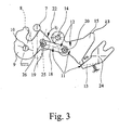
- the case 9 is on the one hand in a component 2 holding engagement position, shown in Fig. 2, on the other hand in a holding element 7 and thus the component 2 releasing release position, shown in Fig. 3 of the drawing, brought.
- the pawl assembly 11 in turn is engageable with the latch 9 in the engaged position holding position and on the other hand in a releasing the case 9 release position.
- the pawl arrangement 11 has a pawl kinematics 12 and an adjustable blocking element 13.
- the blocking element 13 prevents an adjustment of the case 9 from the engaged position (Fig. 2) in the release position (Fig. 3).
- the position shown in Fig. 2 is thus the rest position of the component 2 and the position which is optionally maintained during the entire service life of a motor vehicle by the holding device and the vehicle safety device 1. Regardless of this, a safe release of the component 2 must take place in the shortest possible time in the event of an accident.
- the design of the holding device in detail is of interest. It is initially provided that the pawl kinematics 12 is actively adjusted by the adjustment of the case 9 from the engaged position in the direction of the release position.
- the blocking action of the blocking element 13 So realized by the fact that the effected by the case 9 adjustment of the pawl kinematics 12 is blocked.
- the pawl kinematics 12 configured as a reduction gear, so that the blocking force applied by the blocking element 13 to block the case 9 is reduced according to the design of the reduction gear.
- reduction gear is meant in the present case that the amount of the force acting on the pawl kinematics 12 of the latch 9 is greater than the resultant force acting on the blocking element 13 by the pawl kinematics 12.
- an opening drive A indicated in Fig. 2 causes an adjustment of the blocking element 6 from the blocking position in the dashed lines in Fig. 2, non-blocking position.
- the opening drive A indicated in FIG. 2 is configured as an electromotive worm gear drive.
- Appropriate constructions are widely known from the prior art, for example from the DE 100 38 431 Al.
- the DE 198 21 594 A1 shows, however, an electromagnet as opening drive.
- the pawl kinematics 12 has a pivotable about a pivot axis 14 transmission lever 15.
- the transmission lever 15, in Fig. 2 is adjustable to the left.
- the blocking element 13 blocks the transmission lever 15, so that as a result, the provision of the case 9 is blocked.
- FIG. 5 A particularly simple, realizable with a few components embodiment of the above principle is shown in FIG. 5 in a schematic representation.
- the transmission lever 15 is here on the one hand with the blocking element 13 and on the other hand with the case 9 can be brought into engagement.
- Fig. 5 shows the case 9 in the engaged position and the pawl assembly 3 in the holding position.
- the blocking of the transmission lever 15 is preferably provided by the blocking element 13 in only one pivoting direction of the transmission lever 15. In certain applications, it may also be advantageous that the blocking by the blocking element 13 prevents pivoting of the transmission lever 15 in both pivoting directions.
- the transmission lever 15 is coupled to the case 9 in a motion-coupled manner. This means a positive coupling between the transmission lever 15 and the case 9, which causes an adjustment of the case 9 in principle leads to a corresponding adjustment of the transmission lever 15.
- an intermediate lever 18 is disposed between the transmission lever 15 and the case 9 for the above-mentioned movement coupling, on the one hand and the transmission lever 15 on the other hand is hinged pivotally.
- the pivot point 19 on the case 9 is eccentric with respect to the pivot axis 10 of the case 9, so spaced from the pivot axis 10, arranged. Accordingly, the pivot point 20 on the transmission lever 15 with respect to the pivot axis 14 of the transmission lever 15 is arranged eccentrically.
- the holding device when acting in the engaged position 9, the force acting on the transmission lever 15 via the intermediate lever 18 on the transmission lever 15 causes a torque on the transmission lever 15 with respect to the pivot axis 14, and when the blocking force of the blocking element 13th counteracts this torque.
- a bias voltage is set up in the illustrated embodiment for the transmission lever 15, which counteracts the blocking force of the blocking element 13.
- This bias can also be applied to other components of the Ratchet kinematics 12 may be provided.
- the direction of the bias on the transmission lever 15 is shown by the arrow 22.
- the transmission lever 15 has a detent 23.
- the blocking element 13 is in a preferred embodiment in the manner of a pawl about a pivot axis 24 pivotally. It is further provided a stop on which the blocking element 13 rests in the blocking position and against which acts the bias of a blocking element 13 acting on the spring.
- the blocking element 13 When in holding position pawl assembly 11, the blocking element 13, as described above, in blocking engagement with the transmission lever 15.
- Such a configuration of the blocking element 13 in the manner of a pawl leads to a structurally particularly simple implementation.
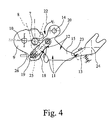
- the articulation of the intermediate lever 18 on the case 9 on a freewheel This makes it possible that an adjustment of the case 9 from the engaged position to a position of the release position from beyond the engaged position lying overstroke position is possible without necessarily to move an adjustment of the transmission lever 15 by itself.
- the overstroke position of the case 9 is briefly occupied when the component 2 is subsequently returned to its rest position after previous release, for example in an accident.
- the transmission lever 15 is meanwhile pressed against the stop in its overstroke position, so that the blocking element 13 can occur in the blocking position.
- the above-mentioned freewheel is realized in that the case 9 has a slot 25 and the intermediate lever 18 has a pin 26 arranged in the slot 25 has.
- the pin 26 runs in the slot 25, as shown in Fig. 4.
- the intermediate lever 18 is biased against the case 9 such that the case can only be brought against the bias in the overstroke.
- This bias can be realized by a biasing spring 27, as shown in Fig. 2.
Landscapes
- Engineering & Computer Science (AREA)
- Mechanical Engineering (AREA)
- Lock And Its Accessories (AREA)
- Seats For Vehicles (AREA)
- Air Bags (AREA)
- Power Steering Mechanism (AREA)
Claims (9)
- Dispositif de maintien pour un dispositif de sécurité d'un véhicule, comportant un composant (2) s'allongeant brusquement d'une position de repos à une position d'action avec un élément de retenue (7), avec un loquet (9) maintenant le composant (2) dans la position de repos et s'accrochant à cet effet à l'élément de retenue (7) du composant (2), dans lequel le loquet (9) peut pivoter autour d'un axe de pivotement (10) et peut ainsi être amené d'une part dans une position d'accrochage retenant le composant (2) et d'autre part dans une position de libération libérant l'élément de retenue (7) et de ce fait le composant (2), avec un dispositif de cliquet d'arrêt (11) retenant le loquet (9) dans la position d'accrochage, dans lequel le dispositif de cliquet d'arrêt (11) peut à son tour être amené dans une position de maintien retenant le loquet (9) dans la position d'accrochage et dans une position de détente libérant le loquet (9), dans lequel le dispositif de cliquet d'arrêt (11) comprend une cinématique du cliquet d'arrêt (12) et un élément de blocage réglable (13), et dans lequel, lorsque le dispositif de cliquet d'arrêt (11) se trouve en position de maintien, l'élément de blocage (13) empêche un déplacement du loquet (9) de la position d'accrochage à la position de libération, caractérisé en ce que la cinématique du cliquet d'arrêt (12) est déplacée par le déplacement du loquet (9) de la position d'accrochage en direction de la position de libération et en ce que l'élément de blocage (13) bloque le déplacement de la cinématique du cliquet d'arrêt (12) actionnable par le loquet (9).
- Dispositif de maintien selon la revendication 1, caractérisé en ce que la cinématique du cliquet d'arrêt (12) est un engrenage réducteur et en ce que la force de blocage à appliquer par l'élément de blocage (13) pour le blocage du loquet (9) est réduite de manière correspondante à la conception de l'engrenage réducteur.
- Dispositif de maintien selon la revendication 1 ou 2, caractérisé en ce que le dispositif de maintien comprend un entraînement d'ouverture motorisé, en particulier un moteur électrique, un électroaimant ou un entraînement pneumatique, pour l'élément de blocage (13), de sorte que la libération du loquet (9) est effectuée au moyen d'un moteur.
- Dispositif de maintien selon l'une quelconque des revendications précédentes, caractérisé en ce que la cinématique du cliquet d'arrêt (12) comprend un levier de transmission (15) pivotant autour d'un axe de pivotement (14), en ce que le levier de transmission (15) est déplaçable, par le pivotement du loquet (9), de la position d'accrochage en direction de la position de libération et en ce que, lorsque le dispositif de cliquet d'arrêt (11) se trouve en position de maintien, l'élément de blocage (13) bloque le levier de transmission (15), de préférence en ce que le levier de transmission (15) est couplé en mouvement avec le loquet (9), de préférence encore en ce qu'un levier intermédiaire (18) est disposé entre le levier de transmission (15) et le loquet (9) pour le couplage du mouvement et en ce que le levier intermédiaire (18) peut pivoter d'une part sur le loquet (9) et d'autre part sur le levier de transmission (15) et est articulé de manière excentrique par rapport à l'axe de pivotement respectif (10, 14), de préférence encore en ce que, lorsque le loquet (9) se trouve en position d'accrochage, la force agissant à partir du loquet (9) sur le levier de transmission (15) via le levier intermédiaire (18) provoque un couple de rotation sur le levier de transmission (15) par rapport à son axe de pivotement (14) et en ce que la force de blocage de l'élément de blocage (13) s'oppose à ce couple de rotation.
- Dispositif de maintien selon la revendication 4, caractérisé en ce que le levier de transmission (15) est précontraint et en ce que la précontrainte du levier de transmission (15) s'oppose à la force de blocage de l'élément de blocage (13).
- Dispositif de maintien selon la revendication 4 et éventuellement selon la revendication 5, caractérisé en ce que le levier de transmission (15) comporte un taquet (23) et en ce que l'élément de blocage (13) peut être amené par le taquet (23) en prise de blocage avec le levier de transmission (15).
- Dispositif de maintien selon la revendication 4 et éventuellement selon la revendication 5 ou 6, caractérisé en ce que l'élément de blocage (13) peut pivoter à la manière d'un cliquet d'arrêt autour d'un axe de pivotement (24) et est en prise de blocage avec le levier de transmission (15) lorsque le dispositif de cliquet d'arrêt (10) se trouve en position de maintien.
- Dispositif de maintien selon la revendication 4 et éventuellement selon l'une quelconque des revendications 5 à 7, caractérisé en ce que l'articulation du levier intermédiaire (18) sur le loquet (9) présente une roue libre et en ce qu'ainsi un déplacement du loquet (9) de la position d'accrochage à une position de dépassement de course située de part et d'autre de la position d'accrochage, vue de la position de libération, est possible sans déplacement du levier de transmission (15).
- Dispositif de maintien selon la revendication 8, caractérisé en ce que le levier intermédiaire (18) est précontraint contre le loquet (9), de telle manière que le loquet (9) puisse être amené dans la position de dépassement de course contre la précontrainte.
Applications Claiming Priority (2)
| Application Number | Priority Date | Filing Date | Title |
|---|---|---|---|
| DE2003158774 DE10358774A1 (de) | 2003-12-12 | 2003-12-12 | Haltevorrichtung für eine Fahrzeugsicherheitseinrichtung |
| DE10358774 | 2003-12-12 |
Publications (2)
| Publication Number | Publication Date |
|---|---|
| EP1541425A1 EP1541425A1 (fr) | 2005-06-15 |
| EP1541425B1 true EP1541425B1 (fr) | 2007-09-26 |
Family
ID=34485393
Family Applications (1)
| Application Number | Title | Priority Date | Filing Date |
|---|---|---|---|
| EP20040027690 Expired - Lifetime EP1541425B1 (fr) | 2003-12-12 | 2004-11-22 | Dispositif de maintien pour un dispositif de sécurité d'un véhicule |
Country Status (4)
| Country | Link |
|---|---|
| US (1) | US7311330B2 (fr) |
| EP (1) | EP1541425B1 (fr) |
| AT (1) | ATE374134T1 (fr) |
| DE (2) | DE10358774A1 (fr) |
Families Citing this family (14)
| Publication number | Priority date | Publication date | Assignee | Title |
|---|---|---|---|---|
| US20070066995A1 (en) * | 2004-06-10 | 2007-03-22 | Ndi Medical, Llc | Implantable pulse generator systems and methods for providing functional and/or therapeutic stimulation of muscles and/or nerves and/or central nervous system tissue |
| DE102005029451A1 (de) * | 2005-06-24 | 2007-01-04 | Wilhelm Karmann Gmbh | Kraftfahrzeug mit einem Überrollschutzsystem |
| US8905434B1 (en) | 2009-11-12 | 2014-12-09 | Excel Industries, Inc. | Rollover protection apparatus |
| US10493939B2 (en) | 2015-02-13 | 2019-12-03 | Excel Industries, Inc. | Lever-actuated operator protection apparatus |
| US9573548B2 (en) | 2015-02-13 | 2017-02-21 | Excel Industries, Inc. | Operator protection apparatus with an over-center linkage |
| US10377333B2 (en) | 2009-11-12 | 2019-08-13 | Excel Industries, Inc. | Deployable operator protection apparatus with an over-center linkage |
| US11724658B2 (en) | 2009-11-12 | 2023-08-15 | Excel Industries, Inc. | Control system for a terrain working vehicle having an operator protection apparatus |
| US11198408B2 (en) | 2009-11-12 | 2021-12-14 | Excel Industries, Inc. | Control system for a terrain working vehicle having an operator protection apparatus |
| US8528950B2 (en) | 2010-02-01 | 2013-09-10 | Strattec Security Corporation | Latch mechanism and latching method |
| US9739077B2 (en) * | 2012-02-16 | 2017-08-22 | Inteva Products, Llc | Linear rotating link switch actuation |
| US9616837B1 (en) | 2014-06-03 | 2017-04-11 | Excel Industries, Inc. | Forward folding roll bar assembly |
| CA3040853A1 (fr) * | 2018-04-21 | 2019-10-21 | David Robertson | Un appareil de protection contre les tonneaux |
| US11788325B2 (en) * | 2019-09-18 | 2023-10-17 | Kyle Meziere | Method and apparatus for soft close trunk latch retrofit |
| CN117868610B (zh) * | 2023-12-22 | 2026-04-07 | 宁波华德汽车零部件有限公司 | 一种不可逆的安全装置、车门把手及其操作方法 |
Family Cites Families (24)
| Publication number | Priority date | Publication date | Assignee | Title |
|---|---|---|---|---|
| US3397911A (en) * | 1964-01-20 | 1968-08-20 | Arthur G. Brosius Sr. | Automotive safety device |
| US3715130A (en) * | 1969-11-05 | 1973-02-06 | I Harada | Shock absorbing device for protecting a rider in a high speed vehicle such as automobile |
| US3885810A (en) * | 1972-01-10 | 1975-05-27 | John J Chika | Seat supporting structure for fast moving vehicles |
| DE3903459A1 (de) * | 1989-02-06 | 1990-08-23 | Audi Ag | Kraftwagen in cabrio-bauweise mit einem ueberrollbuegel |
| DE3922509A1 (de) * | 1989-07-08 | 1991-01-17 | Daimler Benz Ag | Kopfstuetze fuer ruecksitze |
| DE3927265C3 (de) * | 1989-08-18 | 2003-03-27 | Ise Gmbh | Insassenschutzeinrichtung für Kraftfahrzeuge mit einem Überrollbügel |
| DE3930171C2 (de) * | 1989-09-09 | 1996-02-01 | Keiper Recaro Gmbh Co | Überrollschutz |
| DE9321498U1 (de) * | 1993-08-03 | 1998-09-03 | Itt Automotive Europe Gmbh, 60488 Frankfurt | Überrollbügeleinrichtung mit Innenführung und Außenführung |
| DE19650593A1 (de) * | 1996-12-06 | 1998-06-10 | Bayerische Motoren Werke Ag | Überrollschutzsystem für einen Personenkraftwagen |
| DE19750693C2 (de) * | 1997-11-15 | 2002-03-21 | Ise Gmbh | Ausfahrbarer Überrollbügel für Kraftfahrzeuge |
| DE19821549A1 (de) | 1998-05-14 | 1999-05-12 | Daimler Chrysler Ag | Befestigungselement |
| DE19821594C2 (de) * | 1998-05-14 | 2003-11-06 | Thomas Magnete Gmbh | Aktor für Überrollschutzsystem |
| DE19962950C1 (de) * | 1999-12-24 | 2001-03-01 | Daimler Chrysler Ag | Überrollschutzsystem für Kraftfahrzeuge |
| DE10038431A1 (de) * | 2000-08-07 | 2002-02-21 | Volkswagen Ag | Kraftverschluß für eine Fahrzeugsicherheitseinrichtung |
| FR2828517B1 (fr) | 2001-08-13 | 2003-10-03 | Valeo Securite Habitacle | Serrure de vehicule automobile a deux cliquets |
| ES2222410T3 (es) * | 2002-02-21 | 2005-02-01 | Ise Innomotive Systems Europe Gmbh | Dispositivo de proteccion para un cabriole. |
| DE10219447B4 (de) * | 2002-05-02 | 2005-10-20 | Ise Gmbh | Überrollschutzsystem für Kraftfahrzeuge mit einer selbsthaltenden Entriegelungseinrichtung |
| DE10313800A1 (de) * | 2003-03-20 | 2004-09-30 | Brose Fahrzeugteile Gmbh & Co. Kommanditgesellschaft, Coburg | Kopfstützenanordnung für einen Kraftfahrzeugsitz |
| GB0319981D0 (en) * | 2003-08-27 | 2003-10-01 | Ford Global Tech Llc | Roll bar assembly for a vehicle |
| US7246845B2 (en) * | 2003-09-03 | 2007-07-24 | Asc Incorporated | Structural seat system for an automotive vehicle |
| US7341278B2 (en) * | 2004-06-21 | 2008-03-11 | Heuliez | Safety device used in case a vehicle rolls over |
| US20060001248A1 (en) * | 2004-07-02 | 2006-01-05 | Gerard Queveau | Safety device used in case a vehicle rolls over |
| GB0423709D0 (en) * | 2004-10-26 | 2004-11-24 | Ford Global Tech Llc | Motor vehicles incorporating deployable roll bar assemblies |
| DE102004062999A1 (de) * | 2004-12-22 | 2006-07-06 | Dr.Ing.H.C. F. Porsche Ag | Kraftfahrzeug mit einem beweglichen Dach und einem ausfahrbaren Überrollschutzelement |
-
2003
- 2003-12-12 DE DE2003158774 patent/DE10358774A1/de not_active Withdrawn
-
2004
- 2004-11-22 EP EP20040027690 patent/EP1541425B1/fr not_active Expired - Lifetime
- 2004-11-22 DE DE200450005071 patent/DE502004005071D1/de not_active Expired - Fee Related
- 2004-11-22 AT AT04027690T patent/ATE374134T1/de not_active IP Right Cessation
- 2004-12-10 US US11/008,563 patent/US7311330B2/en not_active Expired - Fee Related
Also Published As
| Publication number | Publication date |
|---|---|
| US20050146146A1 (en) | 2005-07-07 |
| DE10358774A1 (de) | 2005-07-14 |
| DE502004005071D1 (de) | 2007-11-08 |
| EP1541425A1 (fr) | 2005-06-15 |
| US7311330B2 (en) | 2007-12-25 |
| ATE374134T1 (de) | 2007-10-15 |
Similar Documents
| Publication | Publication Date | Title |
|---|---|---|
| EP1460211B1 (fr) | Serrure de véhicule automobile | |
| EP1359059B1 (fr) | Système d'arceau de sécurité pour véhicules avec un dispositif de deverrouillage autobloquant | |
| EP1541425B1 (fr) | Dispositif de maintien pour un dispositif de sécurité d'un véhicule | |
| DE4345524C2 (de) | Überrollschutzsystem | |
| WO2014048560A1 (fr) | Enrouleur pour ceinture de sécurité | |
| EP1072485A2 (fr) | Système de ceinture de sécurité | |
| DE102004006873B3 (de) | Kraftfahrzeugsitz | |
| DE102007058335A1 (de) | Überrollschutzvorrichtung | |
| EP0608794B1 (fr) | Entraînement électrique pour arceau de sécurité comportant un écrou de commande | |
| DE10009291B4 (de) | Armlehne mit Staufach und verriegelbarem Deckel | |
| DE102005016488A1 (de) | Vorrichtung zur Festlegung eines ersten Fahrzeugteiles an einem zweiten Fahrzeugteil | |
| EP1724423B1 (fr) | Serrure de véhicule automobile et dispositif de retenue pour un dispositif de sécurité d'un véhicule | |
| WO2021032373A1 (fr) | Système de poignée de porte intérieure destiné à une portière de véhicule automobile | |
| DE19531599A1 (de) | Kupplung für ein in eine Wirkstellung verlagerbares Sicherheitsteil eines Fahrzeugs, insbesondere für einen Überrollbügel | |
| DE10008524B4 (de) | Kraftfahrzeugsitz mit einer klappbaren Rückenlehne und einer höhenverstellbaren Kopfstütze | |
| EP1525121B1 (fr) | Systeme de protection en cas de retournement pour vehicules | |
| DE20113834U1 (de) | Gurtaufroller für einen Fahrzeugsicherheitsgurt | |
| WO2020201441A1 (fr) | Gâche de serrure destinée à une serrure de porte de véhicule à moteur | |
| DE202005005689U1 (de) | Vorrichtung zur Festlegung eines ersten Fahrzeugteiles an einem zweiten Fahrzeugteil | |
| EP1955908A1 (fr) | Système de protection en cas de tonneaux pour véhicules automobiles comprenant un arceau orientable dirigé par capteur pouvant être placé activement | |
| DE102023000508A1 (de) | Schloss für ein Kraftfahrzeug, insbesondere Hauben- oder Klappenschloss | |
| DE102004025052A1 (de) | Vorrichtung zur Höhenverstellung einer Auflagefläche einer Kfz-Armlehne | |
| EP1034987A2 (fr) | Dispositif d'arceau de sécurité pour véhicules | |
| DE19911589C5 (de) | Fahrzeugsitz, insbesondere Kraftfahrzeugsitz, mit einer Betätigungseinrichtung | |
| DE29908320U1 (de) | Höhenverstellvorrichtung für Gurtbeschlag |
Legal Events
| Date | Code | Title | Description |
|---|---|---|---|
| PUAI | Public reference made under article 153(3) epc to a published international application that has entered the european phase |
Free format text: ORIGINAL CODE: 0009012 |
|
| AK | Designated contracting states |
Kind code of ref document: A1 Designated state(s): AT BE BG CH CY CZ DE DK EE ES FI FR GB GR HU IE IS IT LI LU MC NL PL PT RO SE SI SK TR |
|
| AX | Request for extension of the european patent |
Extension state: AL HR LT LV MK YU |
|
| 17P | Request for examination filed |
Effective date: 20051215 |
|
| AKX | Designation fees paid |
Designated state(s): AT BE BG CH CY CZ DE DK EE ES FI FR GB GR HU IE IS IT LI LU MC NL PL PT RO SE SI SK TR |
|
| GRAP | Despatch of communication of intention to grant a patent |
Free format text: ORIGINAL CODE: EPIDOSNIGR1 |
|
| GRAS | Grant fee paid |
Free format text: ORIGINAL CODE: EPIDOSNIGR3 |
|
| GRAA | (expected) grant |
Free format text: ORIGINAL CODE: 0009210 |
|
| AK | Designated contracting states |
Kind code of ref document: B1 Designated state(s): AT BE BG CH CY CZ DE DK EE ES FI FR GB GR HU IE IS IT LI LU MC NL PL PT RO SE SI SK TR |
|
| REG | Reference to a national code |
Ref country code: GB Ref legal event code: FG4D Free format text: NOT ENGLISH |
|
| REG | Reference to a national code |
Ref country code: CH Ref legal event code: EP |
|
| REF | Corresponds to: |
Ref document number: 502004005071 Country of ref document: DE Date of ref document: 20071108 Kind code of ref document: P |
|
| REG | Reference to a national code |
Ref country code: IE Ref legal event code: FG4D Free format text: LANGUAGE OF EP DOCUMENT: GERMAN |
|
| PG25 | Lapsed in a contracting state [announced via postgrant information from national office to epo] |
Ref country code: FI Free format text: LAPSE BECAUSE OF FAILURE TO SUBMIT A TRANSLATION OF THE DESCRIPTION OR TO PAY THE FEE WITHIN THE PRESCRIBED TIME-LIMIT Effective date: 20070926 |
|
| ET | Fr: translation filed | ||
| PG25 | Lapsed in a contracting state [announced via postgrant information from national office to epo] |
Ref country code: PL Free format text: LAPSE BECAUSE OF FAILURE TO SUBMIT A TRANSLATION OF THE DESCRIPTION OR TO PAY THE FEE WITHIN THE PRESCRIBED TIME-LIMIT Effective date: 20070926 |
|
| NLV1 | Nl: lapsed or annulled due to failure to fulfill the requirements of art. 29p and 29m of the patents act | ||
| GBV | Gb: ep patent (uk) treated as always having been void in accordance with gb section 77(7)/1977 [no translation filed] | ||
| PG25 | Lapsed in a contracting state [announced via postgrant information from national office to epo] |
Ref country code: NL Free format text: LAPSE BECAUSE OF FAILURE TO SUBMIT A TRANSLATION OF THE DESCRIPTION OR TO PAY THE FEE WITHIN THE PRESCRIBED TIME-LIMIT Effective date: 20070926 Ref country code: ES Free format text: LAPSE BECAUSE OF FAILURE TO SUBMIT A TRANSLATION OF THE DESCRIPTION OR TO PAY THE FEE WITHIN THE PRESCRIBED TIME-LIMIT Effective date: 20080106 Ref country code: GR Free format text: LAPSE BECAUSE OF FAILURE TO SUBMIT A TRANSLATION OF THE DESCRIPTION OR TO PAY THE FEE WITHIN THE PRESCRIBED TIME-LIMIT Effective date: 20071227 |
|
| REG | Reference to a national code |
Ref country code: IE Ref legal event code: FD4D |
|
| PG25 | Lapsed in a contracting state [announced via postgrant information from national office to epo] |
Ref country code: SK Free format text: LAPSE BECAUSE OF FAILURE TO SUBMIT A TRANSLATION OF THE DESCRIPTION OR TO PAY THE FEE WITHIN THE PRESCRIBED TIME-LIMIT Effective date: 20070926 Ref country code: IS Free format text: LAPSE BECAUSE OF FAILURE TO SUBMIT A TRANSLATION OF THE DESCRIPTION OR TO PAY THE FEE WITHIN THE PRESCRIBED TIME-LIMIT Effective date: 20080126 Ref country code: PT Free format text: LAPSE BECAUSE OF FAILURE TO SUBMIT A TRANSLATION OF THE DESCRIPTION OR TO PAY THE FEE WITHIN THE PRESCRIBED TIME-LIMIT Effective date: 20080226 |
|
| BERE | Be: lapsed |
Owner name: BROSE SCHLIESSSYSTEME G.M.B.H. & CO. KG Effective date: 20071130 |
|
| PG25 | Lapsed in a contracting state [announced via postgrant information from national office to epo] |
Ref country code: RO Free format text: LAPSE BECAUSE OF FAILURE TO SUBMIT A TRANSLATION OF THE DESCRIPTION OR TO PAY THE FEE WITHIN THE PRESCRIBED TIME-LIMIT Effective date: 20070926 Ref country code: MC Free format text: LAPSE BECAUSE OF NON-PAYMENT OF DUE FEES Effective date: 20071130 Ref country code: SE Free format text: LAPSE BECAUSE OF FAILURE TO SUBMIT A TRANSLATION OF THE DESCRIPTION OR TO PAY THE FEE WITHIN THE PRESCRIBED TIME-LIMIT Effective date: 20071226 |
|
| PG25 | Lapsed in a contracting state [announced via postgrant information from national office to epo] |
Ref country code: DK Free format text: LAPSE BECAUSE OF FAILURE TO SUBMIT A TRANSLATION OF THE DESCRIPTION OR TO PAY THE FEE WITHIN THE PRESCRIBED TIME-LIMIT Effective date: 20070926 |
|
| PLBE | No opposition filed within time limit |
Free format text: ORIGINAL CODE: 0009261 |
|
| STAA | Information on the status of an ep patent application or granted ep patent |
Free format text: STATUS: NO OPPOSITION FILED WITHIN TIME LIMIT |
|
| 26N | No opposition filed |
Effective date: 20080627 |
|
| PG25 | Lapsed in a contracting state [announced via postgrant information from national office to epo] |
Ref country code: BE Free format text: LAPSE BECAUSE OF NON-PAYMENT OF DUE FEES Effective date: 20071130 |
|
| PG25 | Lapsed in a contracting state [announced via postgrant information from national office to epo] |
Ref country code: IE Free format text: LAPSE BECAUSE OF FAILURE TO SUBMIT A TRANSLATION OF THE DESCRIPTION OR TO PAY THE FEE WITHIN THE PRESCRIBED TIME-LIMIT Effective date: 20070926 |
|
| PG25 | Lapsed in a contracting state [announced via postgrant information from national office to epo] |
Ref country code: GB Free format text: LAPSE BECAUSE OF FAILURE TO SUBMIT A TRANSLATION OF THE DESCRIPTION OR TO PAY THE FEE WITHIN THE PRESCRIBED TIME-LIMIT Effective date: 20070926 |
|
| PG25 | Lapsed in a contracting state [announced via postgrant information from national office to epo] |
Ref country code: EE Free format text: LAPSE BECAUSE OF FAILURE TO SUBMIT A TRANSLATION OF THE DESCRIPTION OR TO PAY THE FEE WITHIN THE PRESCRIBED TIME-LIMIT Effective date: 20070926 |
|
| PG25 | Lapsed in a contracting state [announced via postgrant information from national office to epo] |
Ref country code: AT Free format text: LAPSE BECAUSE OF NON-PAYMENT OF DUE FEES Effective date: 20071122 |
|
| PGFP | Annual fee paid to national office [announced via postgrant information from national office to epo] |
Ref country code: DE Payment date: 20081130 Year of fee payment: 5 |
|
| PG25 | Lapsed in a contracting state [announced via postgrant information from national office to epo] |
Ref country code: SI Free format text: LAPSE BECAUSE OF FAILURE TO SUBMIT A TRANSLATION OF THE DESCRIPTION OR TO PAY THE FEE WITHIN THE PRESCRIBED TIME-LIMIT Effective date: 20070926 |
|
| REG | Reference to a national code |
Ref country code: CH Ref legal event code: PL |
|
| PG25 | Lapsed in a contracting state [announced via postgrant information from national office to epo] |
Ref country code: CY Free format text: LAPSE BECAUSE OF FAILURE TO SUBMIT A TRANSLATION OF THE DESCRIPTION OR TO PAY THE FEE WITHIN THE PRESCRIBED TIME-LIMIT Effective date: 20070926 |
|
| PG25 | Lapsed in a contracting state [announced via postgrant information from national office to epo] |
Ref country code: LU Free format text: LAPSE BECAUSE OF NON-PAYMENT OF DUE FEES Effective date: 20071122 Ref country code: BG Free format text: LAPSE BECAUSE OF FAILURE TO SUBMIT A TRANSLATION OF THE DESCRIPTION OR TO PAY THE FEE WITHIN THE PRESCRIBED TIME-LIMIT Effective date: 20071226 |
|
| PG25 | Lapsed in a contracting state [announced via postgrant information from national office to epo] |
Ref country code: TR Free format text: LAPSE BECAUSE OF FAILURE TO SUBMIT A TRANSLATION OF THE DESCRIPTION OR TO PAY THE FEE WITHIN THE PRESCRIBED TIME-LIMIT Effective date: 20070926 Ref country code: HU Free format text: LAPSE BECAUSE OF FAILURE TO SUBMIT A TRANSLATION OF THE DESCRIPTION OR TO PAY THE FEE WITHIN THE PRESCRIBED TIME-LIMIT Effective date: 20080327 |
|
| PG25 | Lapsed in a contracting state [announced via postgrant information from national office to epo] |
Ref country code: LI Free format text: LAPSE BECAUSE OF NON-PAYMENT OF DUE FEES Effective date: 20081130 Ref country code: CH Free format text: LAPSE BECAUSE OF NON-PAYMENT OF DUE FEES Effective date: 20081130 |
|
| PGFP | Annual fee paid to national office [announced via postgrant information from national office to epo] |
Ref country code: CZ Payment date: 20091116 Year of fee payment: 6 |
|
| PGFP | Annual fee paid to national office [announced via postgrant information from national office to epo] |
Ref country code: FR Payment date: 20091123 Year of fee payment: 6 |
|
| PG25 | Lapsed in a contracting state [announced via postgrant information from national office to epo] |
Ref country code: DE Free format text: LAPSE BECAUSE OF NON-PAYMENT OF DUE FEES Effective date: 20100601 |
|
| PG25 | Lapsed in a contracting state [announced via postgrant information from national office to epo] |
Ref country code: IT Free format text: LAPSE BECAUSE OF NON-PAYMENT OF DUE FEES Effective date: 20071130 |
|
| PG25 | Lapsed in a contracting state [announced via postgrant information from national office to epo] |
Ref country code: CZ Free format text: LAPSE BECAUSE OF NON-PAYMENT OF DUE FEES Effective date: 20101122 |
|
| REG | Reference to a national code |
Ref country code: FR Ref legal event code: ST Effective date: 20110801 |
|
| PG25 | Lapsed in a contracting state [announced via postgrant information from national office to epo] |
Ref country code: FR Free format text: LAPSE BECAUSE OF NON-PAYMENT OF DUE FEES Effective date: 20101130 |