EP1541433A1 - Balai d'essuie-glace - Google Patents
Balai d'essuie-glace Download PDFInfo
- Publication number
- EP1541433A1 EP1541433A1 EP03766622A EP03766622A EP1541433A1 EP 1541433 A1 EP1541433 A1 EP 1541433A1 EP 03766622 A EP03766622 A EP 03766622A EP 03766622 A EP03766622 A EP 03766622A EP 1541433 A1 EP1541433 A1 EP 1541433A1
- Authority
- EP
- European Patent Office
- Prior art keywords
- wiper blade
- holder
- wiper
- blade
- window glass
- Prior art date
- Legal status (The legal status is an assumption and is not a legal conclusion. Google has not performed a legal analysis and makes no representation as to the accuracy of the status listed.)
- Withdrawn
Links
Images


Classifications
-
- B—PERFORMING OPERATIONS; TRANSPORTING
- B60—VEHICLES IN GENERAL
- B60S—SERVICING, CLEANING, REPAIRING, SUPPORTING, LIFTING, OR MANOEUVRING OF VEHICLES, NOT OTHERWISE PROVIDED FOR
- B60S1/00—Cleaning of vehicles
- B60S1/02—Cleaning windscreens, windows or optical devices
- B60S1/04—Wipers or the like, e.g. scrapers
- B60S1/32—Wipers or the like, e.g. scrapers characterised by constructional features of wiper blade arms or blades
- B60S1/34—Wiper arms; Mountings therefor
- B60S1/3425—Constructional aspects of the arm
- B60S1/3431—Link pieces
-
- B—PERFORMING OPERATIONS; TRANSPORTING
- B60—VEHICLES IN GENERAL
- B60S—SERVICING, CLEANING, REPAIRING, SUPPORTING, LIFTING, OR MANOEUVRING OF VEHICLES, NOT OTHERWISE PROVIDED FOR
- B60S1/00—Cleaning of vehicles
- B60S1/02—Cleaning windscreens, windows or optical devices
- B60S1/04—Wipers or the like, e.g. scrapers
- B60S1/32—Wipers or the like, e.g. scrapers characterised by constructional features of wiper blade arms or blades
- B60S1/38—Wiper blades
- B60S1/3848—Flat-type wiper blade, i.e. without harness
- B60S1/3874—Flat-type wiper blade, i.e. without harness with a reinforcing vertebra
- B60S1/3875—Flat-type wiper blade, i.e. without harness with a reinforcing vertebra rectangular section
- B60S1/3881—Flat-type wiper blade, i.e. without harness with a reinforcing vertebra rectangular section in additional element, e.g. spoiler
-
- B—PERFORMING OPERATIONS; TRANSPORTING
- B60—VEHICLES IN GENERAL
- B60S—SERVICING, CLEANING, REPAIRING, SUPPORTING, LIFTING, OR MANOEUVRING OF VEHICLES, NOT OTHERWISE PROVIDED FOR
- B60S1/00—Cleaning of vehicles
- B60S1/02—Cleaning windscreens, windows or optical devices
- B60S1/04—Wipers or the like, e.g. scrapers
- B60S1/32—Wipers or the like, e.g. scrapers characterised by constructional features of wiper blade arms or blades
- B60S1/38—Wiper blades
- B60S2001/3812—Means of supporting or holding the squeegee or blade rubber
- B60S2001/3813—Means of supporting or holding the squeegee or blade rubber chacterised by a support harness consisting of several articulated elements
-
- B—PERFORMING OPERATIONS; TRANSPORTING
- B60—VEHICLES IN GENERAL
- B60S—SERVICING, CLEANING, REPAIRING, SUPPORTING, LIFTING, OR MANOEUVRING OF VEHICLES, NOT OTHERWISE PROVIDED FOR
- B60S1/00—Cleaning of vehicles
- B60S1/02—Cleaning windscreens, windows or optical devices
- B60S1/04—Wipers or the like, e.g. scrapers
- B60S1/32—Wipers or the like, e.g. scrapers characterised by constructional features of wiper blade arms or blades
- B60S1/38—Wiper blades
- B60S2001/3812—Means of supporting or holding the squeegee or blade rubber
- B60S2001/3817—Means of supporting or holding the squeegee or blade rubber chacterised by a backing strip to aid mounting of squeegee in support
- B60S2001/3818—Means of supporting or holding the squeegee or blade rubber chacterised by a backing strip to aid mounting of squeegee in support the backing strip being a channel-like element, e.g. not continuous
-
- B—PERFORMING OPERATIONS; TRANSPORTING
- B60—VEHICLES IN GENERAL
- B60S—SERVICING, CLEANING, REPAIRING, SUPPORTING, LIFTING, OR MANOEUVRING OF VEHICLES, NOT OTHERWISE PROVIDED FOR
- B60S1/00—Cleaning of vehicles
- B60S1/02—Cleaning windscreens, windows or optical devices
- B60S1/04—Wipers or the like, e.g. scrapers
- B60S1/32—Wipers or the like, e.g. scrapers characterised by constructional features of wiper blade arms or blades
- B60S1/38—Wiper blades
- B60S2001/3812—Means of supporting or holding the squeegee or blade rubber
- B60S2001/3817—Means of supporting or holding the squeegee or blade rubber chacterised by a backing strip to aid mounting of squeegee in support
- B60S2001/382—Means of supporting or holding the squeegee or blade rubber chacterised by a backing strip to aid mounting of squeegee in support the backing strip being an essentially planar reinforcing strip, e.g. vertebra
-
- B—PERFORMING OPERATIONS; TRANSPORTING
- B60—VEHICLES IN GENERAL
- B60S—SERVICING, CLEANING, REPAIRING, SUPPORTING, LIFTING, OR MANOEUVRING OF VEHICLES, NOT OTHERWISE PROVIDED FOR
- B60S1/00—Cleaning of vehicles
- B60S1/02—Cleaning windscreens, windows or optical devices
- B60S1/04—Wipers or the like, e.g. scrapers
- B60S1/32—Wipers or the like, e.g. scrapers characterised by constructional features of wiper blade arms or blades
- B60S1/38—Wiper blades
- B60S2001/3812—Means of supporting or holding the squeegee or blade rubber
- B60S2001/3825—Means of supporting or holding the squeegee or blade rubber the squeegee mounted directly to or in wiper blade arm
Definitions
- the present invention relates to a wiper blade for wiping the surface of a window glass of vehicles.
- a wiper blade mounted on vehicles such as automobiles is used for wiping off such as rain, snow, insects and splash from the preceding vehicle which are attached to a window glass in order to assure the field of view of a driver.
- the wiper blade is mounted on the front edge of the wiper arm connected to such as electric motors and reciprocally oscillates within a wiping area which is set on the window glass surface.
- the wiper arm is provided with a spring therein, and the wiper blade is pressed against the window glass surface by a pressing force transmitted from the spring through the wiper arm.
- the wiper blade can wipe off the window glass by the reciprocal oscillating and the pressing force of the wiper arm.
- the pressing force from the wiper arm should be dispersed over the longitudinal direction of the blade rubber contacting the window glass surface.
- a wiper blade in which a blade rubber and a wiper arm are connected by multi-construction assembled levers is developed and the pressing force is dispersed through the levers.
- the following wiper blade has been developed: a plate type elastic member is mounted over the back face of the blade rubber, and the pressing force from the wiper arm connected to the central portion of the elastic member is dispersed over the longitudinal direction of the blade rubber through the elastic member. The thickness and the width of the elastic member change in the longitudinal direction thereby the dispersed pressure according to the window glass surface to be wiped is applied to the blade rubber.
- the pressing force which is dispersed to the both end portions is less than the pressing force by the wiper arm which acts on the center because a single elastic plate material is attached to the blade rubber.
- elasticity generated when contacting the window glass surface, i.e. a dispersed pressing force is set depend on changing the width and thickness of the plate material, so that the wiper blade should be set according to the curvature of the window glass surface.
- the curvature of window glasses for vehicles is likely to be made different between various types of vehicles because of the design, so that it was necessary to set the dedicated wiper blade for each type of vehicle. Therefore, the versatility of wiper blades is reduced and the production cost of wiper blades may have to increase.
- An object of the present invention is to provide the versatility of wiper blades for window glasses having different curvature.
- the wiper blade of the present invention is mounted on a wiper arm oscillatingly provided on the car body and is reciprocally oscillated as being pressed on a window glass by the wiper arm to wipe the window glass surface.
- the wiper blade comprises a blade rubber for wiping the window glass surface, and a holder piece assembly including a plurality of holder pieces for holding the blade rubber and elastic members for connecting the holder pieces in the longitudinal direction.
- the dispersed pressing force on the wiper blade can be set at the connecting portion of each of the holder pieces.
- the conventional wiper blades should be exclusively set for each type of vehicles because the curvature of the window glass is different between various types of vehicles. While, since the wiper blade according to the present invention can average the dispersed pressing force by changing the connecting angle between each of the holder pieces according to the curvature of the window glass even if it is comprised of the same components, its versatility can be improved. Additionally, if the curvature of the window glass is too large to average the dispersed pressing force only by changing the connecting angle between each holder piece, the length of the holder piece is changed and the elastic modulus of the elastic member is changed so that the pressing force can be averaged by only replacing the minimum component.
- the configuration of the wiper blade of the present invention is simple, the operation of the wiper blade is not blocked and the pressing force can be uniformly dispersed over the blade rubber so that the wiping performance is stabilized. Additionally, the simple configuration of the wipe blade achieves the reduction of the production cost and can be reduced in its height thereby to be downsized. Further, the wiper blade of the present invention is also allowed to conform to the window glass surface having a large curvature and a complicated curved shape and can be easily obtained the dispersed pressing force required for wiping by changing the elastic modulus of the elastic member and the length of the holder piece.
- the wiper blade of the present invention is characterized in that the radius of curvature of the holder piece assembly which is curved by the elastic member when the blade rubber is apart from the window glass surface is smaller than the radius of curvature of the window glass surface.
- the wiper blade of the present invention is characterized in that the holder pieces are integrally molded with the elastic member. Thereby the production cost can be reduced.
- the wiper blade of the present invention is characterized in that the wiper blade comprises a plurality of elastic members and the elastic members connect between each holder piece. Thereby the elastic modulus of the elastic members can be easily changed.
- the wiper blade of the present invention is characterized in that the wiper blade has an auxiliary member for positioning the plurality of elastic members in the longitudinal direction to connect the elastic members. Thereby the production cost can be reduced.
- the wiper blade of the present invention is characterized in that the holder pieces are gradually tapered to the adjacent another holder piece. Thereby the operation of the holder piece assembly is not blocked and the wiping performance can be stabilized.
- the wiper blade of the present invention is characterized in that the holder piece is provided with a holding claw for holding the blade rubber. Thereby the wiper rubber can be easily attached and detached to/from the wiper blade.
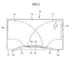
- a wiper apparatus 10 is an opposed-wiping type wiper apparatus, which is mounted on a car body 11 to wipe off rain and splash from the preceding vehicle attached to a window glass 12 (hereinafter referred to as glass 12) of the car body 11 in order to assure the field of view of the driver.
- Wiper arm 13a of the driver's seat side and wiper arm 13b of the passenger's seat side are oppositely mounted each other, and wiper blade 14a and 14b are mounted to each front edge of the wiper arm 13a and 13b, respectively.
- the wiper blade 14a and 14b are elastically and forcingly contacted the glass 12 by such as springs (not shown in the figure) mounted in the wiper arm 13a and 13b.
- Wiper shaft 15a and 15b are provided on both right and left end portions of the car body 11.
- a rotating force of the wiper motor (not shown in the figure) is transmitted to a wiper shaft 15a and 15b through a linkage (not shown in the figure) thereby the wiper shaft 15a and 15b are forward-oscillated and reverse-oscillated repeatedly at a predetermined oscillating angle.
- Each end portion of the wiper arm 13a and 13b is mounted to the wiper shaft 15a and 15b, respectively.
- the wiper arm 13a and 13b are oscillated at a predetermined oscillating angle.
- each wiper blade 14a and 14b is reciprocally oscillated between upper reversing positions 16a and 17a set on the vicinity of both right and left sides of the glass 12 and lower reversing positions 16b and 17b set on the vicinity of the bottom of the glass 12 thereby to wipe off such as raindrops attached to wiping areas 16 and 17 (indicated by each alternate long and short dash line in FIG. 1).
- the wiper blade 14b of the passenger's seat side is disposed in the vicinity of the bottom of the glass 12 and the wiper 14a of the driver's seat side is disposed above the wiper blade 14b.
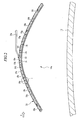
- FIG. 2 is a front view showing the wiper blade 14a in FIG. 1 which is in the state apart from the glass 12, and FIG. 3 is a perspective view showing a part of the wiper blade 14a in FIG. 2 from the direction of arrow A.
- the member indicated by the broken line in FIG. 3 is incorporated into the wiper blade 14a.
- the wiper blade 14a of the driver's seat side is shown in the figure here, and also the wiper blade 14b of the passenger's seat side has the same configuration as the 14a.
- the wiper blade 14a has holder pieces 18a-18i having generally rectangular solid shape which is made of the resin material.
- the holder pieces 18a-18i are continuously arranged in the longitudinal direction to form a holder piece assembly 20.
- Each of the holder pieces 18a-18i is interconnected by leaf spring members 19a-19h as the elastic members provided therein, and each of the holder pieces 18a-18i is interconnected at a predetermined connecting angle. That is to say, the leaf spring members 19a-19h apply the elastic force to each of the holder pieces 18a-18i in the closing direction toward the glass 12 thereby the holder piece assembly 20 is curved in the longitudinal direction by the elastic force from the leaf spring members 19a-19h.
- Blade rubber 21 for wiping the glass 12 surface by slidably contacting thereto is held on the bottom of the holder piece assembly 20.
- Clip pin 22 is provided on the holder piece 18e approximately centered on the holder piece assembly 20.
- the front edge of the wiper arm 13a and the wiper blade 14a are connected therebetween via the clip pin 22.
- the radius of curvature of the holder piece assembly 20 curved in the longitudinal direction is set to smaller than the radius of curvature of the glass 12.
- FIG. 4A is a sectional view showing the wiper blade 14a taken along the A-A line in FIG. 3
- FIG. 4B is a sectional view showing the wiper blade 14a taken along the B-B line in FIG. 3
- FIG. 4C is a sectional view showing the wiper blade 14a taken along the C-C line in FIG. 3, respectively.
- the blade rubber 21 for wiping the glass 12 surface has a base 23 held by the holder pieces 18a-18i and edge 24 for wiping in contact with the glass 12 surface.
- the base 23 and the edge 24 are connected through a neck portion 25 formed in an elongated shape.
- the edge 24 can be moved with inclining by means of the neck portion 25 and is maintained at an appropriate contact angle in order to completely wipe off during contacting the glass 12 surface.
- the base 23 is provided with retaining grooves 26.
- the retaining grooves 26 are engaged with holding claws 27 which are formed at both bottom ends of each of the holder pieces 18a-18i so that the blade rubber 21 is held to the holder pieces 18a-18i.
- supporting grooves 28 are formed above the retaining grooves 26, and thin plate shaped metal cores, i.e. vertebras 29 are inserted into the supporting grooves 28.
- the vertebras 29 provide a predetermined rigidity to the base 23 of the blade rubber 21.
- the retaining groove 26 and the holding claw 27 have a slight gap therebetween thereby the blade rubber 21 is attachable and detachable to/from the holder piece assembly 20.
- Any one end face of the holder pieces 18a and 18i which are disposed at both end of the wiper blade 14a is opened to have the blade rubber 21 inserted therethrough so that only the blade rubber 21 can be easily replaced.
- the opening portion of the holder pieces 18a or 18i is closed by a cap member (not shown in the figure) after inserting the blade rubber 21 therethrough thereby the blade rubber 21 is prevented from dropping off.
- the material for the blade rubber is such as natural rubber and chloroprene rubber, and the composite material of the natural rubber and chloroprene rubber is commonly used so as to have both advantages.
- the blade rubber 21 is produced by extrusion molding those materials and has a uniform cross-section in the longitudinal direction.
- the leaf spring members 19a-19h connecting each of the holder pieces 18a-18i are provided in the holder piece 18a-18i above the blade rubber 21.
- a mold for molding the resinous holder pieces 18a-18i is previously provided with the leaf spring members 19a-19h and the holder pieces 18a-18i and the leaf spring members 19a-19h are integrally produced upon molding the holder pieces 18a-18i.
- the leaf spring members 19a-19h are provided with a plurality of through-holes 31 serving as stoppers for preventing from falling off. The resin is supplied into the through-holes 31 on molding thereby the leaf spring members 19a-19h are prevented from falling off.
- the stoppers are not limited to the plurality of through holes 31 but single through hole 31 or a cavity may be applied.
- the shape is not limited to a circle but the other shape such as a rectangle may be applied. Additionally, the thickness of the leaf springs 19a-19h may as well be partially changed to prevent from falling off thereof.
- the holder piece assembly 20 can be easily produced by molding a plurality of holder pieces 18a-18i together with the leaf spring members 19a-19h without assembly processes. Then, the blade rubber 21 including the vertebras 29 therein are inserted through the holding claws 27 of the holder piece assembly 20 so that the wiper blade 14a can be completed. That is, the wiper blade 14a of the present invention is easily produced without assembling a number of levers as the conventional wiper blades so that the production cost of the wiper blade 14a can be reduced. Additionally, since it dose not have the levers assembled in multi-constructions, the compact wiper blade 14a is achieved.
- FIG. 5 is a plan view showing one example of the leaf spring members before molding.
- each of the leaf spring members 19a-19h may be connected through an auxiliary member 32.
- the connection through the auxiliary member 32 can allow the leaf spring members 19a-19h to be previously positioned as the molding arrangement. Thereby the individual leaf spring member 19a-19h can be easily arranged.
- the leaf spring members 19a-19h are cut out in the connecting state on forming of the leaf spring members 19a-19h and then the connected portions may be folded at a predetermined angle.
- FIG. 6 is a front view showing that the wiper blade 14a in FIG. 2 is pressed against the glass 12.
- the arrow with slanted line shows the pressing force from the wiper arm 13a, and the plain arrows show the dispersed pressing force.
- the holder piece assembly 20 having a radius of curvature smaller than that of the glass 12 surface allows the radius of curvature thereof to conform with the radius of curvature of the glass 12 surface, while elastically deforming the leaf spring members 19a-19h connecting between each of the holder pieces 18a-18i. Therefore, the blade rubber 21 held by the holder piece assembly 20 becomes closely contacted to the glass 12 surface.
- FIG. 7A is an enlarged view showing the range I in FIG. 2, and FIG. 7B is an enlarged view showing the range II in FIG. 6.
- the leaf spring members 19a-19h connecting each of the holder pieces 18a-18i are in the state applied with the gravity affecting the holder piece assembly 20 and with the blade rubber 21 and the reaction force by which the blade rubber 21 is inclined to recover from the curved state. Therefore, the leaf spring members 19a-19h are not applied with any external force other than the gravity and the reaction force, and become not elastically deformed in large.
- the leaf spring members 19a-19h for connecting each of the holder pieces 18a-18i are elastically deformed according to the curvature variation of the holder piece assembly 20.
- the end of each of the holder pieces 18a-18i has inclined surfaces 33a and 33b such that the holder pieces 18a-18i are gradually tapered toward the adjacent holder pieces 18a-18i. Thereby the adjacent holder pieces 18a-18i do not abut each other so that the curvature variation of the holder piece assembly 20 is not limited.
- the holder pieces 18a-18i are applied with the elastic force in the indicated direction by the arrow as shown in FIG. 7B from the elastic deformed leaf spring members 19a-19h.
- the elastic force is transmitted to the blade rubber 21 through the holder pieces 18a-18i thereby a uniform thin water screen is created between the blade rubber 21 and the glass 12 so that the field of view can be assured.
- the elastic force from the each leaf spring member 19a-19h becomes force for pressing each of the holder pieces 18a-18i to the direction of the glass 12 and the force is transmitted in the longitudinal direction of the blade rubber 21 through the holder pieces 18a-18i.
- the pressing force which is applied at a point from the wiper arm 13a as shown by the shaded arrows varies the curvature of the holder piece assembly 20 and becomes force for elastically deforming each leaf spring member 19a-19h, while the elastic force from each leaf member 19a-19h is transmitted to the contact surface of the blade rubber 21 contacting to the glass 12 so that the pressing force of the wiper arm 13a is dispersedly transmitted over the longitudinal direction of the wiper blade 14a.
- the leaf spring members 19a-19h are elastically deformed by the pressing force from the wiper arm 13a such that the holder piece assembly 20 is allowed to conform with the curvature of the glass 12.
- the reaction force of the leaf spring members 19a-19h caused by the elastic deformation is transmitted to the holder pieces 18a-18i thereby the holder piece assembly 20 generates force for pressing the blade rubber 21 against the glass 12.
- the vertebra 29 is mounted to the blade rubber 21.
- the average pressing force is distributed in the longitudinal direction of the blade rubber 21 by dispersing the pressing force over the blade rubber 21. Therefore the wiping performance of the wiper blade 14a can be uniformly achieved.
- the wiper blade 14a which can adapt to the other type of vehicles, i.e. the glass 12 having the different curvature is achieved while most of components constituting the wiper blade 14a can be commonly used. Further, if the glass has a large curvature and a complicated curved surface shape, it can be easily conformed only by exchanging components of the blade rubber 21 thereby the pressing force for wiping can be uniformly dispersed over the longitudinal direction of the blade rubber 21. Incidentally, even if the holder piece assembly 20 is set to as described above, it is not enlarged in size.
- the gap of the holder piece assembly 20 of the wiper blade 14a is not large enough to be intervened by snow and ice so that the operation of the holder piece assembly 20 is not blocked. Therefore, the pressing force is constantly and uniformly dispersed over the blade rubber 21 without being affected by the weather so that the stability of the wiping performance can be achieved.
- the holder piece assembly 20 is provided over the top surface of the blade rubber 21, the blade rubber 21 is prevented from exposing to sun beam thereby the deterioration caused by the aging of the blade rubber 21 can be reduced. Additionally, the design of the wiper blade 14a also can be improved by using the holder piece assembly 20.
- FIG. 8 is a perspective view showing a part of the wiper blade 34 according to another embodiment of the present invention.
- elastic members are not limited to the leaf spring members 19a-19h which individually connects each of the holder pieces 18a-18i, and rod spring members 35a-35c for connecting the holder pieces 18a-18i therethrough may be applied.
- the rod spring members 35a-35c are integrally molded with the holder pieces 18a-18i after bending at a predetermined angle.
- the holder pieces 18a-18i may be penetrated therethrough by the coupled leaf spring members 19a-19h.
- the elastic members are not only provided between each of the holder pieces 18a-18i, but also three or more holder pieces may be connected by one elastic member. Thereby the number of processes on molding can be decreased so that the production cost is reduced.
- the holder piece assembly 20 is formed of nine holder pieces 18a-18i made of the resin material in the present embodiment, however, the number of holder pieces may be changed according the length of the wiper blade to be set and the curved shape of the glass 12 to be wiped, and the holder pieces 18a-18i may be made of such as metals other than the resin.
- the inclined surface 33b formed below among the inclined surface 33a and 33b which are formed on the end of the holder pieces 18a-18i may be eliminated because it dose not affect the direction to which the curvature of the holder piece assembly 20 is decreased.
- the slight gap is provided between the leaf spring members 19a-19h and the blade rubber 21, however, it may be narrowed to the extent that the elastic deformation of the leaf spring members 19a-19h is not blocked.
- the attaching portion of the arm not only the connecting by the clip according to the present embodiment, but also the connecting portion such as a U shaped arm and a bayonet type arm may be used.
- the wiper blade of the present invention is described based on the wiper blade 14a of the driver's seat side, however the wiper blade 14b of the passenger's seat side may be of course applied to the present invention.
- the present invention can be applied to produce various wiper blades which are conformed to window glasses having each different curvature.
Landscapes
- Engineering & Computer Science (AREA)
- Mechanical Engineering (AREA)
- Transmission Devices (AREA)
- Cleaning Implements For Floors, Carpets, Furniture, Walls, And The Like (AREA)
- Body Structure For Vehicles (AREA)
Applications Claiming Priority (3)
| Application Number | Priority Date | Filing Date | Title |
|---|---|---|---|
| JP2002223805 | 2002-07-31 | ||
| JP2002223805 | 2002-07-31 | ||
| PCT/JP2003/008660 WO2004012967A1 (fr) | 2002-07-31 | 2003-07-08 | Balai d'essuie-glace |
Publications (2)
| Publication Number | Publication Date |
|---|---|
| EP1541433A1 true EP1541433A1 (fr) | 2005-06-15 |
| EP1541433A4 EP1541433A4 (fr) | 2006-04-05 |
Family
ID=31492114
Family Applications (1)
| Application Number | Title | Priority Date | Filing Date |
|---|---|---|---|
| EP03766622A Withdrawn EP1541433A4 (fr) | 2002-07-31 | 2003-07-08 | Balai d'essuie-glace |
Country Status (5)
| Country | Link |
|---|---|
| US (1) | US7254862B2 (fr) |
| EP (1) | EP1541433A4 (fr) |
| JP (1) | JP4344692B2 (fr) |
| CN (1) | CN1671581A (fr) |
| WO (1) | WO2004012967A1 (fr) |
Cited By (7)
| Publication number | Priority date | Publication date | Assignee | Title |
|---|---|---|---|---|
| EP1574410A4 (fr) * | 2002-12-17 | 2006-04-12 | Mitsuba Corp | Balai d'essuie-glace |
| FR2879541A1 (fr) * | 2004-12-22 | 2006-06-23 | Renault Sas | Raclette pour balai d'essuie-glace |
| FR2879985A1 (fr) * | 2004-12-23 | 2006-06-30 | Renault Sas | Balai d'essuie-glace |
| FR2890026A1 (fr) * | 2005-08-29 | 2007-03-02 | Valeo Systemes Dessuyage | Balai d'essuie-glace comportant une monture de support en deux parties |
| WO2008019903A1 (fr) * | 2006-08-18 | 2008-02-21 | Robert Bosch Gmbh | Raclette d'essuie-glace |
| EP1816041A4 (fr) * | 2004-11-09 | 2008-11-05 | Mitsuba Corp | Balai d essuie-glace |
| EP1769987A4 (fr) * | 2004-06-18 | 2008-11-05 | Mitsuba Corp | Balai d'essuie-glace |
Families Citing this family (16)
| Publication number | Priority date | Publication date | Assignee | Title |
|---|---|---|---|---|
| US7712180B2 (en) * | 2003-03-07 | 2010-05-11 | Mitsuba Corporation | Wiper blade |
| DE102005041349A1 (de) * | 2005-08-31 | 2007-03-01 | Basf Ag | Reinigungsformulierungen für die maschinelle Geschirrreinigung enthaltend hydrophil modifizierte Polycarboxylate |
| US7647669B2 (en) * | 2006-02-23 | 2010-01-19 | Hai Rwei Heng Enterprise Co., Ltd. | Windshield wiper blade assembly |
| FR2902393B1 (fr) * | 2006-06-14 | 2009-02-20 | Valeo Systemes Dessuyage | Procede de fabrication d'un balai d'essuie-glace |
| ITTO20070136A1 (it) * | 2007-02-27 | 2008-08-28 | Giovanni Creaco | Tergicristallo per autoveicoli. |
| US7540062B1 (en) | 2008-02-20 | 2009-06-02 | Shih-Hsien Huang | Structure for array combinational type of windshield wiper |
| US7540061B1 (en) | 2008-02-20 | 2009-06-02 | Shih-Hsien Huang | Array combinational type of windshield wiper |
| DE102008012466A1 (de) | 2008-03-04 | 2009-09-17 | Shih-Hsien Huang | Anordnungs-kombinatorischer Typ eines Frontscheibenwischers |
| DE102008012464A1 (de) | 2008-03-04 | 2009-09-17 | Shih-Hsien Huang | Aufbau für einen Anordnungs-kombinatorischen Typ eines Frontscheibenwischers |
| CA2721538A1 (fr) * | 2008-04-15 | 2009-10-22 | Jamak Fabrication-Tex, Llc | Ensemble d'essuie-glace de vehicule |
| FR2954250B1 (fr) * | 2009-12-21 | 2014-07-04 | Airbus Operations Sas | Balai d'essuie-glace a flexibilite verticale modifiable |
| DE102010062992A1 (de) * | 2010-12-14 | 2012-06-14 | Robert Bosch Gmbh | Wischerabdeckung |
| CN103282246B (zh) * | 2010-12-27 | 2015-09-30 | 株式会社美姿把 | 刮水器叶片 |
| KR101914818B1 (ko) * | 2011-12-14 | 2018-12-28 | 페더랄-모굴 에스.아. | 윈드스크린 와이퍼 아암 |
| DE102014201829A1 (de) | 2014-02-03 | 2015-08-06 | Robert Bosch Gmbh | Scheibenwischvorrichtung |
| CN115257638B (zh) * | 2021-08-25 | 2025-12-16 | 刘锋 | 具有调节功能的雨刮 |
Family Cites Families (26)
| Publication number | Priority date | Publication date | Assignee | Title |
|---|---|---|---|---|
| GB427383A (en) * | 1933-08-21 | 1935-04-23 | Vauxhall Motors Ltd | Improvements in or relating to windscreen wipers |
| US2589339A (en) * | 1946-04-24 | 1952-03-18 | Gen Motors Corp | Windshield wiper blade |
| US2616113A (en) * | 1947-01-21 | 1952-11-04 | Trico Products Corp | Windshield cleaner |
| US2847694A (en) * | 1953-07-02 | 1958-08-19 | Herbert I Chambers | Windshield wiper for curved glass |
| US2901761A (en) * | 1955-03-23 | 1959-09-01 | Gen Motors Corp | Windshield wiper blade assembly |
| US3041654A (en) * | 1957-03-25 | 1962-07-03 | John W Anderson | Windshield wiper blade |
| US2996746A (en) * | 1958-10-01 | 1961-08-22 | Trico Products Corp | Windscreen wipers |
| US3116507A (en) * | 1960-05-02 | 1964-01-07 | Trico Products Corp | Windshield wiper system |
| US3140501A (en) * | 1961-10-12 | 1964-07-14 | Anderson Co | Windshield wiper blade |
| GB1107141A (en) * | 1964-08-18 | 1968-03-20 | Trico Folberth Ltd | Improvements in windscreen wipers |
| GB1425568A (en) * | 1972-06-20 | 1976-02-18 | Trico Floberth Ltd | Windscreen wiper blade assemblies |
| US4127912A (en) * | 1977-12-15 | 1978-12-05 | Trico Products Corporation | Wiper blade |
| FR2448460A1 (fr) * | 1979-02-12 | 1980-09-05 | Marchal Equip Auto | Essuie-glace, notamment pour vehicules automobiles |
| JPS63199986A (ja) | 1987-02-14 | 1988-08-18 | Toshiba Corp | 調節弁監視装置 |
| JPS63199868U (fr) * | 1987-03-09 | 1988-12-22 | ||
| GB8726140D0 (en) * | 1987-11-07 | 1987-12-09 | Wright C W | Wiper blades |
| JPH01178168A (ja) | 1988-01-05 | 1989-07-14 | Mitsubishi Electric Corp | ディスク記録媒体再生信号の波形等化回路 |
| JPH01178168U (fr) * | 1988-06-06 | 1989-12-20 | ||
| FR2664218B1 (fr) * | 1990-07-05 | 1992-09-11 | Valeo Systemes Dessuyage | Balai d'essuie-glace, notamment pour vehicule automobile. |
| US5485650A (en) * | 1992-10-23 | 1996-01-23 | Adriaan Retief Swanepoel | Windscreen wiper with elongated, curved backbone |
| JP3630781B2 (ja) | 1995-07-26 | 2005-03-23 | アスモ株式会社 | ワイパブレード |
| JP3653874B2 (ja) * | 1996-06-24 | 2005-06-02 | 市光工業株式会社 | ウインター用ワイパーブレードにおけるバーティブラ |
| DE19645170A1 (de) * | 1996-11-02 | 1998-05-07 | Bosch Gmbh Robert | Wischblatt für Scheiben von Kraftfahrzeugen |
| DE19859077A1 (de) * | 1998-12-21 | 2000-06-29 | Bosch Gmbh Robert | Scheibenwischer |
| JP2001328511A (ja) * | 2000-05-18 | 2001-11-27 | Maruenu Kk | ワイパーブレード |
| JP3940982B2 (ja) * | 2000-06-28 | 2007-07-04 | 株式会社ワイ・コーポレーション | ワイパーブレード装置 |
-
2003
- 2003-07-08 CN CNA038183048A patent/CN1671581A/zh active Pending
- 2003-07-08 JP JP2004525781A patent/JP4344692B2/ja not_active Expired - Fee Related
- 2003-07-08 US US10/523,157 patent/US7254862B2/en not_active Expired - Fee Related
- 2003-07-08 EP EP03766622A patent/EP1541433A4/fr not_active Withdrawn
- 2003-07-08 WO PCT/JP2003/008660 patent/WO2004012967A1/fr not_active Ceased
Cited By (10)
| Publication number | Priority date | Publication date | Assignee | Title |
|---|---|---|---|---|
| EP1574410A4 (fr) * | 2002-12-17 | 2006-04-12 | Mitsuba Corp | Balai d'essuie-glace |
| EP1769987A4 (fr) * | 2004-06-18 | 2008-11-05 | Mitsuba Corp | Balai d'essuie-glace |
| US8959703B2 (en) | 2004-06-18 | 2015-02-24 | Mitsuba Corporation | Wiper blade |
| EP1816041A4 (fr) * | 2004-11-09 | 2008-11-05 | Mitsuba Corp | Balai d essuie-glace |
| US8151406B2 (en) | 2004-11-09 | 2012-04-10 | Mitsuba Corporation | Wiper blade |
| FR2879541A1 (fr) * | 2004-12-22 | 2006-06-23 | Renault Sas | Raclette pour balai d'essuie-glace |
| FR2879985A1 (fr) * | 2004-12-23 | 2006-06-30 | Renault Sas | Balai d'essuie-glace |
| FR2890026A1 (fr) * | 2005-08-29 | 2007-03-02 | Valeo Systemes Dessuyage | Balai d'essuie-glace comportant une monture de support en deux parties |
| WO2007025614A1 (fr) * | 2005-08-29 | 2007-03-08 | Valeo Systemes D'essuyage | Balai d'essuie-glace comportant une monture de support en deux parties |
| WO2008019903A1 (fr) * | 2006-08-18 | 2008-02-21 | Robert Bosch Gmbh | Raclette d'essuie-glace |
Also Published As
| Publication number | Publication date |
|---|---|
| EP1541433A4 (fr) | 2006-04-05 |
| JPWO2004012967A1 (ja) | 2006-09-21 |
| CN1671581A (zh) | 2005-09-21 |
| JP4344692B2 (ja) | 2009-10-14 |
| US20060162114A1 (en) | 2006-07-27 |
| WO2004012967A1 (fr) | 2004-02-12 |
| US7254862B2 (en) | 2007-08-14 |
Similar Documents
| Publication | Publication Date | Title |
|---|---|---|
| US7254862B2 (en) | Wiper blade | |
| EP1816041B1 (fr) | Balai d essuie-glace | |
| EP1769987B1 (fr) | Balai d'essuie-glace | |
| US8713747B2 (en) | Wiper coupler and wiper assembly incorporating same | |
| JP4344701B2 (ja) | ワイパブレード及びその製造方法 | |
| EP2103490B1 (fr) | Dispositif d'essuie-glace | |
| KR20060133055A (ko) | 지지 프레임, 내부 스파인 및 링크 요소를 구비하는윈드스크린 와이퍼 블레이드 | |
| US20060218740A1 (en) | Wiper coupler and wiper assembly incorporating same | |
| EP2470402B1 (fr) | Ensemble essuie-glace | |
| CN104691506A (zh) | 扁平雨刮器及其耦合方法 | |
| US20150013093A1 (en) | Wiper coupler adaptor and wiper assembly incorporating same | |
| EP1574410A1 (fr) | Balai d'essuie-glace | |
| JP3653874B2 (ja) | ウインター用ワイパーブレードにおけるバーティブラ | |
| JP3630781B2 (ja) | ワイパブレード | |
| EP1564094B1 (fr) | Dispositif d'essuie-glace | |
| US9744945B2 (en) | End cap for retaining wiping element of wiper assembly | |
| US20250026313A1 (en) | Adapter for a wiping system | |
| JP2950120B2 (ja) | ワイパー装置 | |
| JP7820068B2 (ja) | ワイパブレード | |
| JP2004058957A (ja) | ワイパブレード | |
| KR20080006534U (ko) | 스포일러 부재 및 이를 구비한 와이퍼 블레이드 | |
| JP2006062557A (ja) | ワイパブレード | |
| JPH0715466U (ja) | ワイパー装置 | |
| US9493140B2 (en) | Coupler assembly for wiper assembly | |
| JP2008162590A (ja) | ブレードラバー |
Legal Events
| Date | Code | Title | Description |
|---|---|---|---|
| PUAI | Public reference made under article 153(3) epc to a published international application that has entered the european phase |
Free format text: ORIGINAL CODE: 0009012 |
|
| 17P | Request for examination filed |
Effective date: 20050128 |
|
| AK | Designated contracting states |
Kind code of ref document: A1 Designated state(s): AT BE BG CH CY CZ DE DK EE ES FI FR GB GR HU IE IT LI LU MC NL PT RO SE SI SK TR |
|
| RBV | Designated contracting states (corrected) |
Designated state(s): DE FR |
|
| A4 | Supplementary search report drawn up and despatched |
Effective date: 20060220 |
|
| 17Q | First examination report despatched |
Effective date: 20060727 |
|
| STAA | Information on the status of an ep patent application or granted ep patent |
Free format text: STATUS: THE APPLICATION HAS BEEN WITHDRAWN |
|
| 18W | Application withdrawn |
Effective date: 20101130 |