EP1541468B1 - Aufhängung für Mantelstromtriebwerk - Google Patents
Aufhängung für Mantelstromtriebwerk Download PDFInfo
- Publication number
- EP1541468B1 EP1541468B1 EP04257025A EP04257025A EP1541468B1 EP 1541468 B1 EP1541468 B1 EP 1541468B1 EP 04257025 A EP04257025 A EP 04257025A EP 04257025 A EP04257025 A EP 04257025A EP 1541468 B1 EP1541468 B1 EP 1541468B1
- Authority
- EP
- European Patent Office
- Prior art keywords
- engine
- bypass duct
- assembly
- arrangement
- mounting
- Prior art date
- Legal status (The legal status is an assumption and is not a legal conclusion. Google has not performed a legal analysis and makes no representation as to the accuracy of the status listed.)
- Ceased
Links
- 230000000712 assembly Effects 0.000 claims description 13
- 238000000429 assembly Methods 0.000 claims description 13
- 230000001627 detrimental effect Effects 0.000 description 2
- 230000033001 locomotion Effects 0.000 description 2
- 230000005540 biological transmission Effects 0.000 description 1
- 238000010276 construction Methods 0.000 description 1
Images


Classifications
-
- B—PERFORMING OPERATIONS; TRANSPORTING
- B64—AIRCRAFT; AVIATION; COSMONAUTICS
- B64D—EQUIPMENT FOR FITTING IN OR TO AIRCRAFT; FLIGHT SUITS; PARACHUTES; ARRANGEMENT OR MOUNTING OF POWER PLANTS OR PROPULSION TRANSMISSIONS IN AIRCRAFT
- B64D27/00—Arrangement or mounting of power plants in aircraft; Aircraft characterised by the type or position of power plants
- B64D27/40—Arrangements for mounting power plants in aircraft
- B64D27/402—Arrangements for mounting power plants in aircraft comprising box like supporting frames, e.g. pylons or arrangements for embracing the power plant
-
- F—MECHANICAL ENGINEERING; LIGHTING; HEATING; WEAPONS; BLASTING
- F02—COMBUSTION ENGINES; HOT-GAS OR COMBUSTION-PRODUCT ENGINE PLANTS
- F02C—GAS-TURBINE PLANTS; AIR INTAKES FOR JET-PROPULSION PLANTS; CONTROLLING FUEL SUPPLY IN AIR-BREATHING JET-PROPULSION PLANTS
- F02C7/00—Features, components parts, details or accessories, not provided for in, or of interest apart form groups F02C1/00 - F02C6/00; Air intakes for jet-propulsion plants
- F02C7/20—Mounting or supporting of plant; Accommodating heat expansion or creep
Definitions
- This invention concerns aircraft engine mounting assemblies, and also gas turbine aircraft engines incorporating such assemblies.
- the nacelle In high speed aircraft applications it is considered desirable on the engines for the nacelle to be wrapped tightly to the engine case to reduce the drag caused by the nacelle. This can mean that the space to fit a conventional engine mounting between the outer engine duct, i.e. structural bypass duct, and the nacelle is very limited.
- US5,746,391 discloses a mounting for connecting a turbofan gas turbine engine to an aircraft structure.
- the mounting comprises a link arrangement having three mounting points on the airframe and three mounting points on a turbofan casing, with support rods connecting the turbofan casing to the turbine core engine casing and to airframe.
- an aircraft engine mounting assembly the engine having a core engine casing and a structural bypass duct, the assembly including a pair of inclined links extending from spaced locations on the engine core casing to a bracket arrangement located on the structural bypass duct wherein the bracket arrangement locates in an opening in the structural bypass duct and includes a first part and a second part located on the exterior and interior of the structural bypass duct respectively each overlapping the structural bypass duct around the opening; in normal operation said arrangement does not substantially engage with the structural bypass duct and transmits engine loads directly into the airframe, but upon a failure of part of the engine mounting the bracket arrangement will engage with the structural bypass duct to transmit engine loads into the airframe via the structural bypass duct.
- the mounting assembly is preferably arranged such that the first and second parts substantially only transmit loads to the structural bypass duct following a failure of part of the engine mounting.
- Seals may be provided between the first part and the structural bypass duct, and/or the second part and the structural bypass duct.
- the first and/or second parts may be in the form of plates.
- a body may extend between the first and second parts, which body mounts the respective ends of the links.
- a seal may be provided around the body and engageable with the edge of the opening in the structural bypass duct.
- the first part may be releasably mounted on the body whereby to facilitate engine removal.
- the assembly is preferably provided towards the rear of the engine.
- the invention also provides a gas turbine engine mounting arrangement, the arrangement including at least one assembly according to any of the preceding six paragraphs.
- the gas turbine engine mounting arrangement may also include a plurality of link assemblies extending between the engine core casing and the structural bypass duct.
- the link assemblies and the mounting assemblies may be substantially equispaced around the engine, and three link assemblies and one mounting assembly may be provided.
- Fig. 1 shows the mounting of a gas turbine engine 1 under a wing 2 of an aircraft.
- a front mounting plane 3 and a rear mounting plane 4 are provided.
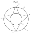
- Fig. 2 illustrates the rear mounting plane 4 with the engine core casing in the form of a tail bearing housing 10 being mounted to and spaced from the structural bypass duct 12 by three link assemblies 5 and an engine mounting assembly 14 according to the invention.
- the assemblies 5, 14 are equispaced around the housing 10, with the assembly 14 immediately beneath the wing 2.
- Fig. 3 shows the engine mounting assembly 14 including a bracket arrangement 16 which locates in an opening 18 provided in the duct 12.
- the arrangement 16 comprises a first part in the form of an exterior plate 20 which is located on the exterior of the duct 12 so as to overlap the edges of the opening 18.
- a second part in the form of an interior plate 22 is provided on the interior of the duct 12 again overlapping the edges of the opening 18.
- the arrangement 16 also comprises a body 24 extending between the plates 20,22 through the opening 18 and a little below the interior plate 22.
- a seal 26 is provided between the body 24 and the edge of the opening 18. Further seals 28 are provided between the plates 20,22 adjacent their perimeter and the duct 12.
- Bolts 30 around the exterior plate 20 to the body 24 are removable to readily permit removal of the engine.
- a pair of links 30 extend from the body 24 in an A-frame arrangement to spaced locations on the tail bearing housing 10.
- the links 30 are mounted so as to permit movement relative to the housing 10 and body 24.
- the opening 18 provides sufficient clearance for relative motions due to thermal growth or load induced deflections during normal operation.
- the load would then be transmitted at least in part onto the duct 12, by virtue of engagement of the plates 20,22 on the duct 12 around the opening 18.
- the bypass duct 12 is kept concentric to the engine core casing by means of the link assemblies 5 such that in the event of an engine mounting failure such as a failed link, any engine loads are passed via the link assemblies 5 into the structural bypass duct 12, and then via the body 24 to the airframe.
- the body 24 could be utilised as a failsafe catcher for engine thrust loads, whether or not the remainder of the rear mounting plane 4 is in its usual unfailed condition.
Landscapes
- Engineering & Computer Science (AREA)
- Chemical & Material Sciences (AREA)
- Combustion & Propulsion (AREA)
- Aviation & Aerospace Engineering (AREA)
- Mechanical Engineering (AREA)
- General Engineering & Computer Science (AREA)
- Structures Of Non-Positive Displacement Pumps (AREA)
Claims (12)
- Aufhängevorrichtung für ein Flugtriebwerk, wobei die Vorrichtung (14) ein Triebwerk (1) mit einem Kerntriebwerksgehäuse (10) und einem strukturellen Mantelstromkanal (12) aufweist und die Vorrichtung weiter einen Lenker (30) umfasst, der sich vom Kerntriebwerksgehäuse (10) nach einer Trägeranordnung (16) erstreckt, die auf dem strukturellen Mantelstromkanal (12) angeordnet ist,
dadurch gekennzeichnet, dass die Vorrichtung (14) ein Paar geneigter Lenker (30) aufweist, die sich von im Abstand liegenden Stellen des Kerntriebwerksgehäuses (10) nach der Trägeranordnung (16) erstrecken, wobei die Trägeranordnung (16) in einer Öffnung (18) in dem strukturellen Mantelstromkanal (12) angeordnet ist und einen ersten Teil (20) und einen zweiten Teil (22) aufweist, die außerhalb bzw. innerhalb des strukturellen Mantelstromkanals (12) angeordnet sind und beide den strukturellen Mantelstromkanal (12) um die Öffnung (18) herum überlappen, wobei im Normalbetrieb die Anordnung (16) nicht wesentlich an dem strukturellen Mantelstromkanal (12) angreift und dadurch Triebwerksbelastungen direkt auf die Flugzeugzelle überträgt, wobei jedoch im Falle eines Defektes eines Teils der Triebwerksaufhängung (30) die Trägeranordnung (16) an dem strukturellen Mantelstromkanal (12) angreift, um die Triebwerksbelastungen über den strukturellen Mantelstromkanal (12) auf die Flugzeugzelle zu übertragen. - Vorrichtung nach Anspruch 1,
dadurch gekennzeichnet, dass die Aufhängevorrichtung derart angeordnet ist, dass der erste Teil (20) und der zweite Teil (22) im Wesentlichen nur dann Belastungen auf den strukturellen Mantelstromkanal (12) übertragen, wenn ein Teil der Triebwerksaufhängung (30) beschädigt ist. - Vorrichtung nach den Ansprüchen 1 und 2,
dadurch gekennzeichnet, dass Dichtungen (28) zwischen dem ersten Teil (20) und dem strukturellen Mantelstromkanal (12) und/oder dem zweiten Teil (22) und dem strukturellen Mantelstromkanal (12) vorgesehen sind. - Vorrichtung nach einem der Ansprüche 1 bis 3,
dadurch gekennzeichnet, dass der erste und/oder der zweite Teil (20, 22) in Form von Platten ausgebildet ist. - Vorrichtung nach einem der Ansprüche 1 bis 4,
dadurch gekennzeichnet, dass sich ein Aufbau (24) zwischen dem ersten und zweiten Teil (20, 22) erstreckt und dieser Aufbau (24) die jeweiligen Enden der Lenker (30 lagert. - Vorrichtung nach Anspruch 5,
dadurch gekennzeichnet, dass eine Dichtung (26) um den Aufbau (24) herum angeordnet ist und an dem Rand der Öffnung (18) im strukturellen Mantelstromkanal (12) angreift. - Vorrichtung nach den Ansprüchen 5 oder 6,
dadurch gekennzeichnet, dass der erste Teil (20) lösbar an dem Aufbau (24) befestigt ist, wodurch die Demontage des Triebwerks erleichtert wird. - Vorrichtung nach einem der vorhergehenden Ansprüche,
dadurch gekennzeichnet, dass der Aufbau (14) nach dem rückwärtigen Teil des Triebwerks hin angeordnet ist. - Aufhängevorrichtung für ein Gasturbinenflugtriebwerk,
dadurch gekennzeichnet, dass die Vorrichtung wenigstens einen Aufbau (14) gemäß einem der vorhergehenden Ansprüche aufweist. - Triebwerk nach Anspruch 9,
dadurch gekennzeichnet, dass die Aufhängevorrichtung außerdem mehrere Lenkeranordnungen (5) aufweist, die sich zwischen dem Kerntriebwerksgehäuse (10) und dem strukturellen Mantelstromkanal (12) erstrecken. - Vorrichtung nach Anspruch 10,
dadurch gekennzeichnet, dass die Lenkeranordnungen (5) und der Lageraufbau (14) im gleichen Abstand um das Triebwerk (1) herum angeordnet sind. - Vorrichtung nach den Ansprüchen 10 oder 11,
dadurch gekennzeichnet, dass drei Lenkeranordnungen (5) und ein Lageraufbau (14) vorgesehen sind.
Applications Claiming Priority (2)
| Application Number | Priority Date | Filing Date | Title |
|---|---|---|---|
| GB0328671 | 2003-12-11 | ||
| GBGB0328671.3A GB0328671D0 (en) | 2003-12-11 | 2003-12-11 | Aircraft engine mounting |
Publications (2)
| Publication Number | Publication Date |
|---|---|
| EP1541468A1 EP1541468A1 (de) | 2005-06-15 |
| EP1541468B1 true EP1541468B1 (de) | 2007-01-03 |
Family
ID=30129997
Family Applications (1)
| Application Number | Title | Priority Date | Filing Date |
|---|---|---|---|
| EP04257025A Ceased EP1541468B1 (de) | 2003-12-11 | 2004-11-11 | Aufhängung für Mantelstromtriebwerk |
Country Status (4)
| Country | Link |
|---|---|
| US (1) | US7313920B2 (de) |
| EP (1) | EP1541468B1 (de) |
| DE (1) | DE602004004052T2 (de) |
| GB (1) | GB0328671D0 (de) |
Cited By (1)
| Publication number | Priority date | Publication date | Assignee | Title |
|---|---|---|---|---|
| US9828105B2 (en) | 2011-08-24 | 2017-11-28 | United Technologies Corporation | Nacelle assembly having integrated afterbody mount case |
Families Citing this family (12)
| Publication number | Priority date | Publication date | Assignee | Title |
|---|---|---|---|---|
| GB0607991D0 (en) * | 2006-04-22 | 2006-05-31 | Rolls Royce Plc | Aeroengine mounting |
| FR2905975B1 (fr) * | 2006-09-20 | 2008-12-05 | Snecma Sa | Conduite de soufflante pour une turbomachine. |
| FR2920198B1 (fr) | 2007-08-20 | 2009-10-30 | Aircelle Sa | Structure pour inverseur de poussee |
| FR2928180B1 (fr) * | 2008-02-28 | 2010-04-02 | Airbus France | Ensemble moteur pour aeronef comprenant une structure annulaire de transfert d'efforts entourant le carter central d'un turboreacteur. |
| US8979491B2 (en) | 2009-05-15 | 2015-03-17 | Pratt & Whitney Canada Corp. | Turbofan mounting arrangement |
| US8313293B2 (en) * | 2009-05-15 | 2012-11-20 | Pratt & Whitney Canada Corp. | Turbofan mounting system |
| US8567202B2 (en) * | 2009-05-15 | 2013-10-29 | Pratt & Whitney Canada Corp. | Support links with lockable adjustment feature |
| FR2956164B1 (fr) * | 2010-02-10 | 2012-02-24 | Snecma | Liaison entre le carter d'echappement et un anneau structural de conduit de soufflante d'un turboreacteur |
| US9194296B2 (en) | 2012-05-18 | 2015-11-24 | Pratt & Whitney Canada Corp. | Inner bypass duct wall attachment |
| DE102013007607A1 (de) * | 2013-05-03 | 2014-11-06 | Rolls-Royce Deutschland Ltd & Co Kg | Gasturbinentriebwerk mit modularem Nebenstromgehäuse |
| CN105392700B (zh) | 2013-07-26 | 2018-12-18 | Mra系统有限责任公司 | 飞行器发动机吊架 |
| US11585274B2 (en) | 2020-12-28 | 2023-02-21 | General Electric Company | Turbine rear frame link assemblies for turbofan engines |
Family Cites Families (17)
| Publication number | Priority date | Publication date | Assignee | Title |
|---|---|---|---|---|
| GB1074068A (en) | 1964-09-22 | 1967-06-28 | Rolls Royce | Mounting arrangement for gas turbine jet propulsion engines |
| US3318554A (en) * | 1964-09-22 | 1967-05-09 | Rolls Royce | Mounting arrangement for engines |
| US3398535A (en) * | 1966-05-25 | 1968-08-27 | Gen Electric | Engine supporting structure |
| US3397855A (en) * | 1966-12-01 | 1968-08-20 | United Aircraft Canada | Rear mount system for aircraft engines |
| GB1318748A (en) * | 1970-08-11 | 1973-05-31 | Secr Defence | Gas turgine ducted fan engines for aircraft |
| US3907220A (en) * | 1974-03-14 | 1975-09-23 | United Aircraft Corp | Rear engine redundant mount |
| US4266741A (en) * | 1978-05-22 | 1981-05-12 | The Boeing Company | Mounting apparatus for fan jet engine having mixed flow nozzle installation |
| SU849694A1 (ru) | 1980-03-12 | 1996-09-20 | А.А. Бобух | Устройство для крепления двухконтурного турбореактивного двигателя |
| DE3374545D1 (en) * | 1983-12-08 | 1987-12-23 | Boeing Co | Aft engine mount |
| WO1991005150A1 (en) * | 1989-09-29 | 1991-04-18 | Sundstrand Corporation, Inc. | Geodesic engine mount structure |
| US5076049A (en) * | 1990-04-02 | 1991-12-31 | General Electric Company | Pretensioned frame |
| FR2676707B1 (fr) * | 1991-05-23 | 1993-08-13 | Snecma | Nacelle pour suspendre sous l'aile d'un avion un groupe turboreacteur du type a double flux. |
| GB2303884B (en) * | 1995-04-13 | 1999-07-14 | Rolls Royce Plc | A mounting for coupling a turbofan gas turbine engine to an aircraft structure |
| US5927644A (en) * | 1997-10-08 | 1999-07-27 | General Electric Company | Double failsafe engine mount |
| GB2394991B (en) * | 2002-11-06 | 2006-02-15 | Rolls Royce Plc | Mounting arrangement |
| FR2855496B1 (fr) * | 2003-05-27 | 2006-09-22 | Snecma Moteurs | Suspension arriere de moteur d'avion avec reprise de poussee |
| US7083143B2 (en) * | 2003-10-17 | 2006-08-01 | The Boeing Company | Apparatuses and methods for attaching engines and other structures to aircraft wings |
-
2003
- 2003-12-11 GB GBGB0328671.3A patent/GB0328671D0/en not_active Ceased
-
2004
- 2004-11-11 EP EP04257025A patent/EP1541468B1/de not_active Ceased
- 2004-11-11 DE DE602004004052T patent/DE602004004052T2/de not_active Expired - Lifetime
- 2004-12-02 US US11/001,122 patent/US7313920B2/en not_active Expired - Fee Related
Cited By (1)
| Publication number | Priority date | Publication date | Assignee | Title |
|---|---|---|---|---|
| US9828105B2 (en) | 2011-08-24 | 2017-11-28 | United Technologies Corporation | Nacelle assembly having integrated afterbody mount case |
Also Published As
| Publication number | Publication date |
|---|---|
| US20050230532A1 (en) | 2005-10-20 |
| US7313920B2 (en) | 2008-01-01 |
| DE602004004052D1 (de) | 2007-02-15 |
| EP1541468A1 (de) | 2005-06-15 |
| DE602004004052T2 (de) | 2007-04-12 |
| GB0328671D0 (en) | 2004-01-14 |
Similar Documents
| Publication | Publication Date | Title |
|---|---|---|
| EP1541468B1 (de) | Aufhängung für Mantelstromtriebwerk | |
| EP0250659B1 (de) | Triebwerksaufhängungssystem mit Schwingungsdämpfern | |
| US6843449B1 (en) | Fail-safe aircraft engine mounting system | |
| JP4498694B2 (ja) | 単一のスラストリンクを有する航空機エンジンマウント | |
| EP1010879B1 (de) | Getriebeaufhängung | |
| US8469309B2 (en) | Monolithic structure for mounting aircraft engine | |
| US8844862B2 (en) | Aft pylon fairing for aircraft engine suspension system, comprising a heat shield capable of expanding freely | |
| CA2726503C (en) | Integrated nacelle assembly | |
| EP2332835B1 (de) | Montagesystem in einer Ebene für einen Gasturbinenmotor | |
| EP1847457B1 (de) | Aufhängung eines Flugzeugtriebwerks | |
| US5871176A (en) | Redundant front suspension system for a turboshaft engine | |
| EP2330036B1 (de) | Träger eines Verdichterhaubenteils für ein Mantelstromtriebwerk | |
| US6401448B1 (en) | System for mounting aircraft engines | |
| US7448808B2 (en) | Arrangement of bearing supports for the rotating shaft of an aircraft engine and an aircraft engine fitted with such an arrangement | |
| EP2441673B1 (de) | Aufhängungsstruktur | |
| US10358226B2 (en) | Assembly for an aircraft including a fitting secured to the upper surface of a wing box, for mounting an engine strut to said wing box | |
| EP2221249B1 (de) | Eine Schubkräfte aufnehmende Flugzeugtriebwerkaufhängung | |
| US9359954B2 (en) | In-line removable heat shield for a turbomachine suspension yoke | |
| EP1712466B1 (de) | Aufhängevorrichtung für eine Gasturbine | |
| US8038092B2 (en) | Engine assembly for aircraft | |
| EP0849165B1 (de) | Flugzeugstruktur mit Antriebsanlage | |
| EP1707760B1 (de) | Montagestruktur einer Schubumkehrvorrichtung | |
| EP2841339B1 (de) | Redundante befestigung eines turbinenabgasgehäuses | |
| CN214617699U (zh) | 航空发动机传扭机构及航空发动机 |
Legal Events
| Date | Code | Title | Description |
|---|---|---|---|
| PUAI | Public reference made under article 153(3) epc to a published international application that has entered the european phase |
Free format text: ORIGINAL CODE: 0009012 |
|
| 17P | Request for examination filed |
Effective date: 20050314 |
|
| AK | Designated contracting states |
Kind code of ref document: A1 Designated state(s): AT BE BG CH CY CZ DE DK EE ES FI FR GB GR HU IE IS IT LI LU MC NL PL PT RO SE SI SK TR |
|
| AX | Request for extension of the european patent |
Extension state: AL HR LT LV MK YU |
|
| AKX | Designation fees paid |
Designated state(s): DE FR GB |
|
| GRAP | Despatch of communication of intention to grant a patent |
Free format text: ORIGINAL CODE: EPIDOSNIGR1 |
|
| GRAS | Grant fee paid |
Free format text: ORIGINAL CODE: EPIDOSNIGR3 |
|
| GRAA | (expected) grant |
Free format text: ORIGINAL CODE: 0009210 |
|
| AK | Designated contracting states |
Kind code of ref document: B1 Designated state(s): DE FR GB |
|
| REG | Reference to a national code |
Ref country code: GB Ref legal event code: FG4D |
|
| REF | Corresponds to: |
Ref document number: 602004004052 Country of ref document: DE Date of ref document: 20070215 Kind code of ref document: P |
|
| ET | Fr: translation filed | ||
| PLBE | No opposition filed within time limit |
Free format text: ORIGINAL CODE: 0009261 |
|
| STAA | Information on the status of an ep patent application or granted ep patent |
Free format text: STATUS: NO OPPOSITION FILED WITHIN TIME LIMIT |
|
| 26N | No opposition filed |
Effective date: 20071005 |
|
| REG | Reference to a national code |
Ref country code: FR Ref legal event code: PLFP Year of fee payment: 12 |
|
| REG | Reference to a national code |
Ref country code: FR Ref legal event code: PLFP Year of fee payment: 13 |
|
| REG | Reference to a national code |
Ref country code: FR Ref legal event code: PLFP Year of fee payment: 14 |
|
| PGFP | Annual fee paid to national office [announced via postgrant information from national office to epo] |
Ref country code: DE Payment date: 20181128 Year of fee payment: 15 |
|
| PGFP | Annual fee paid to national office [announced via postgrant information from national office to epo] |
Ref country code: FR Payment date: 20181127 Year of fee payment: 15 Ref country code: GB Payment date: 20181127 Year of fee payment: 15 |
|
| REG | Reference to a national code |
Ref country code: DE Ref legal event code: R119 Ref document number: 602004004052 Country of ref document: DE |
|
| GBPC | Gb: european patent ceased through non-payment of renewal fee |
Effective date: 20191111 |
|
| PG25 | Lapsed in a contracting state [announced via postgrant information from national office to epo] |
Ref country code: DE Free format text: LAPSE BECAUSE OF NON-PAYMENT OF DUE FEES Effective date: 20200603 Ref country code: GB Free format text: LAPSE BECAUSE OF NON-PAYMENT OF DUE FEES Effective date: 20191111 Ref country code: FR Free format text: LAPSE BECAUSE OF NON-PAYMENT OF DUE FEES Effective date: 20191130 |