EP1541736A2 - Dispositif de verrouillage pour une bobine de fil de canette - Google Patents
Dispositif de verrouillage pour une bobine de fil de canette Download PDFInfo
- Publication number
- EP1541736A2 EP1541736A2 EP04405582A EP04405582A EP1541736A2 EP 1541736 A2 EP1541736 A2 EP 1541736A2 EP 04405582 A EP04405582 A EP 04405582A EP 04405582 A EP04405582 A EP 04405582A EP 1541736 A2 EP1541736 A2 EP 1541736A2
- Authority
- EP
- European Patent Office
- Prior art keywords
- bobbin
- locking element
- coil
- locking device
- locking
- Prior art date
- Legal status (The legal status is an assumption and is not a legal conclusion. Google has not performed a legal analysis and makes no representation as to the accuracy of the status listed.)
- Granted
Links
Images


Classifications
-
- D—TEXTILES; PAPER
- D05—SEWING; EMBROIDERING; TUFTING
- D05B—SEWING
- D05B57/00—Loop takers, e.g. loopers
- D05B57/26—Bobbin holders or casings; Bobbin holder or case guards; Bobbin discharge devices
Definitions
- the invention relates to a locking device for a bobbin according to the preamble of Patent claim 1.
- the bobbin of sewing machines can either be stored directly in the bobbin and is thus directly accessible or it can be inserted in a specially designed bobbin case, which in turn is mounted in the bobbin.
- the present invention relates to a bobbin mounted directly in the bobbin; However, it can also be used for a coil mounted indirectly in a bobbin case.
- a bobbin case for rotary gripper is known, in which the coil on a cylindrical bobbin, which is part of the bobbin case, pushed and held by a safety lever.
- the safety lever designed as a two-armed lever, is held in the two positions (open position and working position) by a spring-loaded plate.
- the locking is released by manually turning the lever by 90 ° into an axially parallel position. Thereafter, the coil can be lifted out of the bobbin.
- a coil spring between the coil base, ie the underlying coil flange, and the bobbin. This pushes after release of the coil by the lever, the coil partially out of the bobbin.
- the spring exerts during braking a braking torque on the coil, which varies depending on the design of the coil surface and can not be influenced. This can hinder the sewing process.
- a spool holder in which the spool is held by a spring-loaded retaining mandrel passing through the spool.
- the retaining pin can be brought by a quarter turn out of the holding in the removal position and dissolves completely together with the coil from the bobbin. The retaining pin must therefore be inserted into this when inserting a full bobbin and then secured.
- An object of the present invention is the creation a locking device for a bobbin, held with the lower thread bobbin in the bobbin can be without uncontrollable braking forces on they act, and in addition an axial pushing out the coil or the bobbin case from the bobbin the unlocking causes.
- the Holding position which caught the coil in the bobbin holds, dissolved and at the same time the partial ejection of the Coil can be initiated.
- the locking of a new in the bobbin to be inserted coil is done by axial insertion of the coil in the bobbin, until these in the recess in the bobbin abuts. There are then no further interlocking actions necessary.
- the held by the locking element coil is through Braking the locking element in no way, because the latter does not touch the coil frictionally.
- the only two-part locking element is captive connected to the bobbin and remains even after removing the coil on the bobbin.
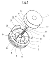
- reference numeral 1 denotes a coil carrier for a coil 3.
- the coil 3 may have flanges with or without weight-reducing holes.
- the bobbin 1 comprises a bottom 5, which may be broken to reduce the mass of holes 7.
- a hollow cylindrical spool 9 is formed with a central bore 10.
- the bottom 5 In the shell of which two opposing and axially extending slots 11 and 13 are embedded.
- the bottom 5 In the area of the slots 11, 13, the bottom 5 may be partially broken, so that recesses 15, 17 are formed.
- the two recesses 15,17 are not connected to each other, but they are separated by a web 19 (Fig.2).
- the web 19 is part of the bottom 5.
- the axial extent of the first slot 11 is greater than the axial extent of the second slot 13, so that the upper ends 43,45 of the slots 11 and 13 do not have the same distance from the bottom 5 (see in particular Figure 2).
- the two slots 11,13 form an anti-rotation and an axial stop for a locking element 21, which is biased by a coil spring, short spring 23.
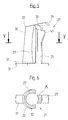
- the locking element 21 comprises two legs 25,27, on each of which an outwardly projecting foot 29,31 is formed.
- the two legs 25,27 are spaced from each other in the substantially cylindrical lateral surface 22 of the locking element 21 and are connected to the feet 29,31 opposite ends with a handle plate 33.
- the two legs 25,27 are produced by a slotted cylinder (see Figure 6).
- a blind bore 32 in the locking element 21 forms a guide for the spring 23.
- the handle plate 33 projects beyond the first leg 25 radially.
- the outer surface 35 of the second leg 27 is flush with the rear edge 37 of the handle plate 33.
- Below the first leg 25 projecting nose 39 is spaced from the lower edge of a handle plate 33 toward stepped shoulder 41.
- the foot 41 is wedge-shaped and goes transition-free into the surface of the foot 25 over.
- the two feet 29, 31 project beyond the jacket of the coil mandrel 9 when the locking element 21 is inserted into the bore 10 in the coil carrier 1 or into the coil mandrel 9 in the coil carrier 1. They are guided laterally in the two slots 11, 13 (cf., FIG. 2).
- the spring 23 is supported on the bottom of the web 19 and the top of the underside of the handle plate 33.
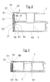
- the locking element 21 can assume two different extreme positions in the spool 9: The spool removal position according to FIG. 2 and the working position according to FIGS. 3 and 4. In the removal position for the coil 3 according to Figure 2, the locking element 21 is located by the force of the spring 23 in its maximum extended position.
- the two feet 29, 31 abut against the two upper ends 43 and 45 of the slots 11 and 13 and prevent the locking element 21 from becoming detached from the spool 9. Because the first slot 11 has a greater axial extent upwards, but the two feet 29, 31 are arranged symmetrically on the locking element 21, the locking element 21 is forcibly moved into an inclined position (see FIG.
- the handle plate 33 moves in the direction of the axis X, so that the rear edge 37 and the front edge 47 of the nose 39 come to lie at the same distance from the axis X.
- This pivoting back of the nose 39 in the direction of the axis of rotation X causes the coil 3 is now freely guided axially over the locking element 21 and removed or placed.
- this is inserted axially until the lower flange 49 of the coil 3 rests for the time being on the higher foot 29 of the locking element 21.
- the locking element 21 is in the unlocked position thanks to play in the bore 10 in the spool 9 obliquely and thereby releases the coil 3.
- the inclined position of the locking element 21 in the extended position according to FIG. 2 could also be achieved if, with the same axial length of the two slots 11, 13, the foot 31 facing the nose 39 would have a greater axial thickness (cf. Line 51 in FIG. 5).
- this design has the disadvantage that the overall height of the bobbin 1 is correspondingly increased, the height of the coil 3 is reduced or the coil would have to be undercut in the central area, so that the additional axial height of the foot 31 can find room in the recess 15.
- the locking element 121 is arranged peripherally on the coil carrier 101.
- the bobbin 101 can also be produced without a central spool, and the locking element 121 is guided in an axial slot 104, which is embedded in the lateral surface 102 of the bobbin 101 (FIGS. 8 and 9).
- the locking element 121 comprises a handle plate 133, a foot 129 and two legs 125 connecting the handle plate 133 and the foot 129.
- the foot 129 and a nose 139 which is part of the handle plate 133, project beyond the surface of the leg 125 and act as stops for the lower flange 49 of the coil 3 and the upper flange of the coil 3.
- the spring 23 is supported at its lower end on the bottom 105 of the bobbin 101.
- the upper end of the spring 23 abuts against a paragraph 141 arranged at a distance from the underside of the handle plate 133 and the nose 139.
- coil 3 are the flanges of the coil 3 with clearance between the foot 129 and the nose 139.
- the paragraph 141 is applied to the upper end 106 of the axial slot 104 pressed by the spring 23 at.
- Invention may be the locking element, similar as in Figures 1 to 5, within the spool 9 to be arranged vertically displaceable and a mechanism include, as with pens for the movement of Mine is used. With the ballpoint pen mechanics known scenes it is also possible to release a locking position by axial pressure and with a spring an axial feed movement trigger and on pressing the latch again to activate again.
- the grip plates 33, 133 are designed in such a way that the lower thread can not catch on being pulled off and also the triggering properties are not impaired.
- the handle plate 33,133 may be formed in the direction of the nose 39,139 out with a suit that the locking element 21,121, if it has been accidentally placed without coil 3 in the inserted position, when pushing a coil 3 is unlocked immediately by the hollow coil mandrel pushes and by reinserting the coil 3 again assumes the coil-locking position.
Landscapes
- Engineering & Computer Science (AREA)
- Textile Engineering (AREA)
- Sewing Machines And Sewing (AREA)
- Replacing, Conveying, And Pick-Finding For Filamentary Materials (AREA)
- Storage Of Web-Like Or Filamentary Materials (AREA)
Applications Claiming Priority (2)
| Application Number | Priority Date | Filing Date | Title |
|---|---|---|---|
| CH21052003 | 2003-12-10 | ||
| CH21052003 | 2003-12-10 |
Publications (3)
| Publication Number | Publication Date |
|---|---|
| EP1541736A2 true EP1541736A2 (fr) | 2005-06-15 |
| EP1541736A3 EP1541736A3 (fr) | 2006-04-26 |
| EP1541736B1 EP1541736B1 (fr) | 2008-05-21 |
Family
ID=34468809
Family Applications (1)
| Application Number | Title | Priority Date | Filing Date |
|---|---|---|---|
| EP04405582A Expired - Lifetime EP1541736B1 (fr) | 2003-12-10 | 2004-09-16 | Dispositif de verrouillage pour une bobine de fil de canette |
Country Status (4)
| Country | Link |
|---|---|
| US (1) | US7036444B2 (fr) |
| EP (1) | EP1541736B1 (fr) |
| AT (1) | ATE396293T1 (fr) |
| DE (1) | DE502004007215D1 (fr) |
Cited By (6)
| Publication number | Priority date | Publication date | Assignee | Title |
|---|---|---|---|---|
| EP2103725A1 (fr) * | 2008-03-19 | 2009-09-23 | Dürkopp Adler AG | Crochet pour une machine à coudre du type à double point noué |
| EP2138623A1 (fr) * | 2008-06-24 | 2009-12-30 | Dürkopp Adler AG | Crochet pour une machine à coudre à double point noué |
| EP2221410A1 (fr) * | 2009-02-17 | 2010-08-25 | BERNINA International AG | Dispositif de verrouillage d' un boîtier de canette |
| ITVI20100069A1 (it) * | 2010-03-15 | 2011-09-16 | Gilberto Cracco | Gruppo crochet perfezionato, particolarmente per macchine da cucire. |
| EP2463430A1 (fr) * | 2010-12-09 | 2012-06-13 | BERNINA International AG | Dispositif de verrouillage pour une boîte à canette |
| CN104278437A (zh) * | 2013-07-03 | 2015-01-14 | 启翔股份有限公司 | 缝纫机水平旋梭 |
Families Citing this family (3)
| Publication number | Priority date | Publication date | Assignee | Title |
|---|---|---|---|---|
| JP2012115595A (ja) * | 2010-12-03 | 2012-06-21 | Brother Ind Ltd | ボビン及びミシン |
| USD843977S1 (en) * | 2017-07-11 | 2019-03-26 | Aiwu Wang | Winder |
| JP1610198S (fr) * | 2017-09-25 | 2018-07-30 |
Family Cites Families (8)
| Publication number | Priority date | Publication date | Assignee | Title |
|---|---|---|---|---|
| US663675A (en) * | 1900-08-07 | 1900-12-11 | Singer Mfg Co | Bobbin-case holder and bobbin-ejector for sewing-machines. |
| US832414A (en) * | 1905-11-16 | 1906-10-02 | Wheeler & Wilson Mfg Co | Sewing-machine bobbin-case. |
| US2813500A (en) * | 1951-06-26 | 1957-11-19 | Singer Mfg Co | Bobbin-cases for sewing machines |
| US2848965A (en) * | 1954-01-25 | 1958-08-26 | White Sewing Machine Corp | Sewing machine |
| US3381643A (en) * | 1966-10-10 | 1968-05-07 | Singer Co | Bobbin-supporting assemblies for sewing machines |
| US4462324A (en) * | 1983-11-07 | 1984-07-31 | The Singer Company | Bobbin and plunger assembly |
| CS262030B1 (en) * | 1987-06-15 | 1989-02-10 | Jaromir Dvoracek | Bobbin case of a rotating looper with vertical axis of rotation |
| DE19510830C2 (de) | 1995-03-24 | 2001-11-22 | Duerkopp Adler Ag | Spulenbremse für die Greiferfaden-Spule einer Doppelsteppstich-Nähmaschine |
-
2004
- 2004-09-16 AT AT04405582T patent/ATE396293T1/de not_active IP Right Cessation
- 2004-09-16 DE DE502004007215T patent/DE502004007215D1/de not_active Expired - Lifetime
- 2004-09-16 EP EP04405582A patent/EP1541736B1/fr not_active Expired - Lifetime
- 2004-10-19 US US10/968,738 patent/US7036444B2/en not_active Expired - Lifetime
Cited By (10)
| Publication number | Priority date | Publication date | Assignee | Title |
|---|---|---|---|---|
| EP2103725A1 (fr) * | 2008-03-19 | 2009-09-23 | Dürkopp Adler AG | Crochet pour une machine à coudre du type à double point noué |
| KR101534860B1 (ko) * | 2008-03-19 | 2015-07-07 | 뒤르콥 아들러 악티엔게젤샤프트 | 록스티치 재봉틀용 후크 |
| EP2138623A1 (fr) * | 2008-06-24 | 2009-12-30 | Dürkopp Adler AG | Crochet pour une machine à coudre à double point noué |
| CN101613915B (zh) * | 2008-06-24 | 2012-12-12 | 杜尔克普-阿德勒股份公司 | 用于双锁式线迹缝纫机的旋梭 |
| EP2221410A1 (fr) * | 2009-02-17 | 2010-08-25 | BERNINA International AG | Dispositif de verrouillage d' un boîtier de canette |
| CH700442A1 (de) * | 2009-02-17 | 2010-08-31 | Bernina Int Ag | Verriegelungsvorrichtung für eine Spulenkapsel für eine Unterfadenspule. |
| ITVI20100069A1 (it) * | 2010-03-15 | 2011-09-16 | Gilberto Cracco | Gruppo crochet perfezionato, particolarmente per macchine da cucire. |
| EP2463430A1 (fr) * | 2010-12-09 | 2012-06-13 | BERNINA International AG | Dispositif de verrouillage pour une boîte à canette |
| US8622009B2 (en) | 2010-12-09 | 2014-01-07 | Bernina International Ag | Locking mechanism for a bobbin case |
| CN104278437A (zh) * | 2013-07-03 | 2015-01-14 | 启翔股份有限公司 | 缝纫机水平旋梭 |
Also Published As
| Publication number | Publication date |
|---|---|
| ATE396293T1 (de) | 2008-06-15 |
| US7036444B2 (en) | 2006-05-02 |
| US20050126461A1 (en) | 2005-06-16 |
| DE502004007215D1 (de) | 2008-07-03 |
| EP1541736B1 (fr) | 2008-05-21 |
| EP1541736A3 (fr) | 2006-04-26 |
Similar Documents
| Publication | Publication Date | Title |
|---|---|---|
| EP1491295B1 (fr) | Boulon pour la fixation d'un élément d'outil sur un outil de sertissage hydraulique | |
| DE2309396C3 (de) | Vorrichtung für Einsatzschraubenschlüssel zur lösbaren axialen Befestigung eines Steckschlüssels | |
| AT411819B (de) | Biegewerkzeug und werkzeugaufnahmevorrichtung für ein solches | |
| DE2729151A1 (de) | Verschlusstueck fuer eine sitzgurtschnalle | |
| EP0458170B1 (fr) | Mandrin | |
| EP1541736B1 (fr) | Dispositif de verrouillage pour une bobine de fil de canette | |
| EP0949424A2 (fr) | Raccord entre composants, en particulier pour panneaux | |
| DE29613690U1 (de) | Gurtstrafferfester Verschluß für Sicherheitsgurte | |
| DE20115941U1 (de) | Verankerungsvorrichtung für Mitnahmestab mit mehreren Abschnitten | |
| CH680400A5 (fr) | ||
| EP0830261B1 (fr) | Dispositif d'attelage | |
| EP1224881A1 (fr) | Boucle de ceinture de sécurité | |
| CH656544A5 (de) | Vorrichtung zur laengsverstellung von skibindungsteilen. | |
| DE3411138A1 (de) | Auswerfmechanismus fuer ein bandabspielgeraet | |
| DE102020131548A1 (de) | Tragstange, Haltevorrichtung und Verfahren zur Herstellung | |
| EP1201853B1 (fr) | Dispositif de fermeture supérieur pour serrure des portes de secours | |
| EP1888280A1 (fr) | Liaison entre deux parties d'outil | |
| DE3342783C2 (de) | Sicherheitsgurtverschluss mit drehbarer Sperrklinke | |
| DE19931953A1 (de) | Beschlag zur Lagerung eines Endes einer Latte eines Lattenrahmens | |
| DE2611739A1 (de) | Vorrichtung zum automatischen greifen von stoffstuecken beliebiger dicke | |
| EP0212322A2 (fr) | Attelage de remorque détachable | |
| EP3296163A1 (fr) | Dispositif sécurisé de fermeture d'un composant essentiellement fonctionnel du véhicule automobile | |
| DE69105209T2 (de) | Kniehebelverschluss für schuhwerk. | |
| AT402021B (de) | Skibindung | |
| DE102010017950B4 (de) | Auswahlplatine |
Legal Events
| Date | Code | Title | Description |
|---|---|---|---|
| PUAI | Public reference made under article 153(3) epc to a published international application that has entered the european phase |
Free format text: ORIGINAL CODE: 0009012 |
|
| AK | Designated contracting states |
Kind code of ref document: A2 Designated state(s): AT BE BG CH CY CZ DE DK EE ES FI FR GB GR HU IE IT LI LU MC NL PL PT RO SE SI SK TR |
|
| AX | Request for extension of the european patent |
Extension state: AL HR LT LV MK |
|
| PUAL | Search report despatched |
Free format text: ORIGINAL CODE: 0009013 |
|
| AK | Designated contracting states |
Kind code of ref document: A3 Designated state(s): AT BE BG CH CY CZ DE DK EE ES FI FR GB GR HU IE IT LI LU MC NL PL PT RO SE SI SK TR |
|
| AX | Request for extension of the european patent |
Extension state: AL HR LT LV MK |
|
| 17P | Request for examination filed |
Effective date: 20060518 |
|
| RAP1 | Party data changed (applicant data changed or rights of an application transferred) |
Owner name: FRITZ GEGAUF AG |
|
| AKX | Designation fees paid |
Designated state(s): AT BE BG CH CY CZ DE DK EE ES FI FR GB GR HU IE IT LI LU MC NL PL PT RO SE SI SK TR |
|
| 17Q | First examination report despatched |
Effective date: 20061228 |
|
| RAP1 | Party data changed (applicant data changed or rights of an application transferred) |
Owner name: BERNINA INTERNATIONAL AG |
|
| GRAP | Despatch of communication of intention to grant a patent |
Free format text: ORIGINAL CODE: EPIDOSNIGR1 |
|
| GRAS | Grant fee paid |
Free format text: ORIGINAL CODE: EPIDOSNIGR3 |
|
| GRAA | (expected) grant |
Free format text: ORIGINAL CODE: 0009210 |
|
| AK | Designated contracting states |
Kind code of ref document: B1 Designated state(s): AT BE BG CH CY CZ DE DK EE ES FI FR GB GR HU IE IT LI LU MC NL PL PT RO SE SI SK TR |
|
| REG | Reference to a national code |
Ref country code: GB Ref legal event code: FG4D Free format text: NOT ENGLISH |
|
| REG | Reference to a national code |
Ref country code: CH Ref legal event code: EP Ref country code: CH Ref legal event code: NV Representative=s name: GACHNANG AG PATENTANWAELTE |
|
| REF | Corresponds to: |
Ref document number: 502004007215 Country of ref document: DE Date of ref document: 20080703 Kind code of ref document: P |
|
| REG | Reference to a national code |
Ref country code: IE Ref legal event code: FG4D Free format text: LANGUAGE OF EP DOCUMENT: GERMAN |
|
| REG | Reference to a national code |
Ref country code: SE Ref legal event code: TRGR |
|
| PG25 | Lapsed in a contracting state [announced via postgrant information from national office to epo] |
Ref country code: SI Free format text: LAPSE BECAUSE OF FAILURE TO SUBMIT A TRANSLATION OF THE DESCRIPTION OR TO PAY THE FEE WITHIN THE PRESCRIBED TIME-LIMIT Effective date: 20080521 |
|
| PG25 | Lapsed in a contracting state [announced via postgrant information from national office to epo] |
Ref country code: ES Free format text: LAPSE BECAUSE OF FAILURE TO SUBMIT A TRANSLATION OF THE DESCRIPTION OR TO PAY THE FEE WITHIN THE PRESCRIBED TIME-LIMIT Effective date: 20080901 Ref country code: FI Free format text: LAPSE BECAUSE OF FAILURE TO SUBMIT A TRANSLATION OF THE DESCRIPTION OR TO PAY THE FEE WITHIN THE PRESCRIBED TIME-LIMIT Effective date: 20080521 |
|
| NLV1 | Nl: lapsed or annulled due to failure to fulfill the requirements of art. 29p and 29m of the patents act | ||
| PG25 | Lapsed in a contracting state [announced via postgrant information from national office to epo] |
Ref country code: NL Free format text: LAPSE BECAUSE OF FAILURE TO SUBMIT A TRANSLATION OF THE DESCRIPTION OR TO PAY THE FEE WITHIN THE PRESCRIBED TIME-LIMIT Effective date: 20080521 Ref country code: PL Free format text: LAPSE BECAUSE OF FAILURE TO SUBMIT A TRANSLATION OF THE DESCRIPTION OR TO PAY THE FEE WITHIN THE PRESCRIBED TIME-LIMIT Effective date: 20080521 |
|
| PGFP | Annual fee paid to national office [announced via postgrant information from national office to epo] |
Ref country code: CZ Payment date: 20080909 Year of fee payment: 5 |
|
| REG | Reference to a national code |
Ref country code: IE Ref legal event code: FD4D |
|
| PG25 | Lapsed in a contracting state [announced via postgrant information from national office to epo] |
Ref country code: PT Free format text: LAPSE BECAUSE OF FAILURE TO SUBMIT A TRANSLATION OF THE DESCRIPTION OR TO PAY THE FEE WITHIN THE PRESCRIBED TIME-LIMIT Effective date: 20081021 Ref country code: DK Free format text: LAPSE BECAUSE OF FAILURE TO SUBMIT A TRANSLATION OF THE DESCRIPTION OR TO PAY THE FEE WITHIN THE PRESCRIBED TIME-LIMIT Effective date: 20080521 Ref country code: IE Free format text: LAPSE BECAUSE OF FAILURE TO SUBMIT A TRANSLATION OF THE DESCRIPTION OR TO PAY THE FEE WITHIN THE PRESCRIBED TIME-LIMIT Effective date: 20080521 |
|
| PG25 | Lapsed in a contracting state [announced via postgrant information from national office to epo] |
Ref country code: SK Free format text: LAPSE BECAUSE OF FAILURE TO SUBMIT A TRANSLATION OF THE DESCRIPTION OR TO PAY THE FEE WITHIN THE PRESCRIBED TIME-LIMIT Effective date: 20080521 Ref country code: RO Free format text: LAPSE BECAUSE OF FAILURE TO SUBMIT A TRANSLATION OF THE DESCRIPTION OR TO PAY THE FEE WITHIN THE PRESCRIBED TIME-LIMIT Effective date: 20080521 |
|
| PLBE | No opposition filed within time limit |
Free format text: ORIGINAL CODE: 0009261 |
|
| STAA | Information on the status of an ep patent application or granted ep patent |
Free format text: STATUS: NO OPPOSITION FILED WITHIN TIME LIMIT |
|
| BERE | Be: lapsed |
Owner name: BERNINA INTERNATIONAL A.G. Effective date: 20080930 |
|
| 26N | No opposition filed |
Effective date: 20090224 |
|
| PG25 | Lapsed in a contracting state [announced via postgrant information from national office to epo] |
Ref country code: BG Free format text: LAPSE BECAUSE OF FAILURE TO SUBMIT A TRANSLATION OF THE DESCRIPTION OR TO PAY THE FEE WITHIN THE PRESCRIBED TIME-LIMIT Effective date: 20080821 Ref country code: EE Free format text: LAPSE BECAUSE OF FAILURE TO SUBMIT A TRANSLATION OF THE DESCRIPTION OR TO PAY THE FEE WITHIN THE PRESCRIBED TIME-LIMIT Effective date: 20080521 Ref country code: MC Free format text: LAPSE BECAUSE OF NON-PAYMENT OF DUE FEES Effective date: 20080930 |
|
| REG | Reference to a national code |
Ref country code: FR Ref legal event code: ST Effective date: 20090529 |
|
| PG25 | Lapsed in a contracting state [announced via postgrant information from national office to epo] |
Ref country code: BE Free format text: LAPSE BECAUSE OF NON-PAYMENT OF DUE FEES Effective date: 20080930 |
|
| PG25 | Lapsed in a contracting state [announced via postgrant information from national office to epo] |
Ref country code: IT Free format text: LAPSE BECAUSE OF FAILURE TO SUBMIT A TRANSLATION OF THE DESCRIPTION OR TO PAY THE FEE WITHIN THE PRESCRIBED TIME-LIMIT Effective date: 20080521 |
|
| PG25 | Lapsed in a contracting state [announced via postgrant information from national office to epo] |
Ref country code: FR Free format text: LAPSE BECAUSE OF NON-PAYMENT OF DUE FEES Effective date: 20080930 Ref country code: AT Free format text: LAPSE BECAUSE OF NON-PAYMENT OF DUE FEES Effective date: 20080916 |
|
| PGFP | Annual fee paid to national office [announced via postgrant information from national office to epo] |
Ref country code: GB Payment date: 20090902 Year of fee payment: 6 Ref country code: SE Payment date: 20090929 Year of fee payment: 6 |
|
| PG25 | Lapsed in a contracting state [announced via postgrant information from national office to epo] |
Ref country code: CZ Free format text: LAPSE BECAUSE OF NON-PAYMENT OF DUE FEES Effective date: 20090916 |
|
| PG25 | Lapsed in a contracting state [announced via postgrant information from national office to epo] |
Ref country code: LU Free format text: LAPSE BECAUSE OF NON-PAYMENT OF DUE FEES Effective date: 20080916 Ref country code: CY Free format text: LAPSE BECAUSE OF FAILURE TO SUBMIT A TRANSLATION OF THE DESCRIPTION OR TO PAY THE FEE WITHIN THE PRESCRIBED TIME-LIMIT Effective date: 20080521 Ref country code: HU Free format text: LAPSE BECAUSE OF FAILURE TO SUBMIT A TRANSLATION OF THE DESCRIPTION OR TO PAY THE FEE WITHIN THE PRESCRIBED TIME-LIMIT Effective date: 20081122 |
|
| PG25 | Lapsed in a contracting state [announced via postgrant information from national office to epo] |
Ref country code: TR Free format text: LAPSE BECAUSE OF FAILURE TO SUBMIT A TRANSLATION OF THE DESCRIPTION OR TO PAY THE FEE WITHIN THE PRESCRIBED TIME-LIMIT Effective date: 20080521 |
|
| PG25 | Lapsed in a contracting state [announced via postgrant information from national office to epo] |
Ref country code: GR Free format text: LAPSE BECAUSE OF FAILURE TO SUBMIT A TRANSLATION OF THE DESCRIPTION OR TO PAY THE FEE WITHIN THE PRESCRIBED TIME-LIMIT Effective date: 20080822 |
|
| REG | Reference to a national code |
Ref country code: SE Ref legal event code: EUG |
|
| GBPC | Gb: european patent ceased through non-payment of renewal fee |
Effective date: 20100916 |
|
| PG25 | Lapsed in a contracting state [announced via postgrant information from national office to epo] |
Ref country code: GB Free format text: LAPSE BECAUSE OF NON-PAYMENT OF DUE FEES Effective date: 20100916 |
|
| PG25 | Lapsed in a contracting state [announced via postgrant information from national office to epo] |
Ref country code: SE Free format text: LAPSE BECAUSE OF NON-PAYMENT OF DUE FEES Effective date: 20100917 |
|
| PGFP | Annual fee paid to national office [announced via postgrant information from national office to epo] |
Ref country code: CH Payment date: 20200929 Year of fee payment: 17 |
|
| PGFP | Annual fee paid to national office [announced via postgrant information from national office to epo] |
Ref country code: DE Payment date: 20201127 Year of fee payment: 17 |
|
| REG | Reference to a national code |
Ref country code: DE Ref legal event code: R119 Ref document number: 502004007215 Country of ref document: DE |
|
| REG | Reference to a national code |
Ref country code: CH Ref legal event code: PL |
|
| PG25 | Lapsed in a contracting state [announced via postgrant information from national office to epo] |
Ref country code: DE Free format text: LAPSE BECAUSE OF NON-PAYMENT OF DUE FEES Effective date: 20220401 |
|
| PG25 | Lapsed in a contracting state [announced via postgrant information from national office to epo] |
Ref country code: LI Free format text: LAPSE BECAUSE OF NON-PAYMENT OF DUE FEES Effective date: 20210930 Ref country code: CH Free format text: LAPSE BECAUSE OF NON-PAYMENT OF DUE FEES Effective date: 20210930 |