EP1541774A2 - Verfahren und Vorrichtung zum hydraulischen Entfernen einer Bohrbrunnenverstopfung - Google Patents
Verfahren und Vorrichtung zum hydraulischen Entfernen einer Bohrbrunnenverstopfung Download PDFInfo
- Publication number
- EP1541774A2 EP1541774A2 EP04300872A EP04300872A EP1541774A2 EP 1541774 A2 EP1541774 A2 EP 1541774A2 EP 04300872 A EP04300872 A EP 04300872A EP 04300872 A EP04300872 A EP 04300872A EP 1541774 A2 EP1541774 A2 EP 1541774A2
- Authority
- EP
- European Patent Office
- Prior art keywords
- volume
- tube
- water
- hydraulic
- unclogging
- Prior art date
- Legal status (The legal status is an assumption and is not a legal conclusion. Google has not performed a legal analysis and makes no representation as to the accuracy of the status listed.)
- Withdrawn
Links
Images

Classifications
-
- E—FIXED CONSTRUCTIONS
- E03—WATER SUPPLY; SEWERAGE
- E03B—INSTALLATIONS OR METHODS FOR OBTAINING, COLLECTING, OR DISTRIBUTING WATER
- E03B3/00—Methods or installations for obtaining or collecting drinking water or tap water
- E03B3/06—Methods or installations for obtaining or collecting drinking water or tap water from underground
- E03B3/08—Obtaining and confining water by means of wells
- E03B3/15—Keeping wells in good condition, e.g. by cleaning, repairing, regenerating; Maintaining or enlarging the capacity of wells or water-bearing layers
-
- E—FIXED CONSTRUCTIONS
- E21—EARTH OR ROCK DRILLING; MINING
- E21B—EARTH OR ROCK DRILLING; OBTAINING OIL, GAS, WATER, SOLUBLE OR MELTABLE MATERIALS OR A SLURRY OF MINERALS FROM WELLS
- E21B37/00—Methods or apparatus for cleaning boreholes or wells
- E21B37/08—Methods or apparatus for cleaning boreholes or wells cleaning in situ of down-hole filters, screens, e.g. casing perforations, or gravel packs
-
- E—FIXED CONSTRUCTIONS
- E21—EARTH OR ROCK DRILLING; MINING
- E21B—EARTH OR ROCK DRILLING; OBTAINING OIL, GAS, WATER, SOLUBLE OR MELTABLE MATERIALS OR A SLURRY OF MINERALS FROM WELLS
- E21B43/00—Methods or apparatus for obtaining oil, gas, water, soluble or meltable materials or a slurry of minerals from wells
- E21B43/25—Methods for stimulating production
Definitions
- the present invention relates to a method for unclogging a hydraulic drilling and the associated device for carrying out this method.
- Water well drilling is a medium-sized, small-diameter structure between 500 and 100 mm that cross the fields until the meeting a permeable zone saturated with water and likely to provide the flow of water research.
- a borehole passes through a first non-permeable zone in which the borehole is cased to the permeable zone in which has a strainer to let the water that is pumped.
- a pump is positioned at the bottom of the borehole and delivers the water area.
- Water from the aquifer is driven by the depression to the wellbore. This water migrates through the cracks, aggregates or porosity of the rock following the natures of ground to join the well.
- microparticles are driven, all the more so that the environment is friable and we can see that the wells, as and when the operation is reduced in yield.
- the first solution is to boost.
- the driller seems the best placed since he can install a piston into the well and maneuver it into the drill pipe to make back and forth and generate pressure / depression cycles.
- a current drawdown is 30m or three bars, so a pressure at least the same or even preferably a pressure of twice to obtain a significant effect.
- the method according to the present invention makes it possible to overcome the problems of the processes of the prior art and proposes a hydraulic process for generate significant declogging pressures, which is implemented on reduced intervention times, which requires adapted equipment also of the present invention.
- the process involves using the borehole as a water tower to accumulate a large volume of water and release it quickly with significant pressure due to the differential water level.
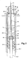
- the device according to the invention consists in removing the pumping means from production to replace them with the declogging head 16 according to this invention.
- This head comprises means 18 for fixing on the drill pipe 10 and a 20 dewatering column suspended from a cable 21.
- the means 18 for fixing include a lid with a sealing flange.
- This column comprises means 22 for closing the drill pipe, delimiting an upper volume V1 and a lower volume V2 .
- sealing means are constituted in this embodiment of a packer 24 inflatable with a supply 26 provided with a valve 28.
- the column comprises a pump 30 which discharges through a discharge tube 32 equipped with a two-way valve 34.
- This valve allows either the circulation of water at the outlet of the pump 30 in the discharge tube 32, arrow 34-1, ie the setting in communication of this tube with the volume of the drilling located above the packer inflatable, arrow 34-2.
- This tube extends outwardly through the means 18 for fixing to a flow meter 36 and a valve 38 for controlling the flow rate.
- the flowmeter is advantageously connected to a central 40 measurement and acquisition.
- the pump 30 is disposed in a partially closed pumping / emptying tube 42 high around the discharge tube 32.
- This tube 42 for pumping / emptying is extended through the inflatable packer 24, tightly, down to the level of the aquifer, below the level of drawdown.
- This tube 42 pumping / emptying is equipped with a valve 44 two-way strong passage section. This valve allows either the passage of water pumped by the pump 30 in the tube 42 for pumping / emptying, arrow 44-1, ie the communication of the volume of the drilling located above the inflatable packer with inside said tube 42 pumping / draining, arrow 44-2.
- a level sensor 46 is disposed in the volume of the borehole located above the inflatable packer. This sensor is connected to the acquisition unit 40.
- the device is completed by a treatment rod 48 which emerges in point high and which is reported by means of a stitching 50 on the tube 42 of pumping / draining located above the inflatable packer.
- a sensor 52 which allows to have the pressure of the volume V2 . This sensor is connected to the acquisition unit 40.
- tapping 54 compressed air reported on the fastening means 18, opening into the volume V1 .
- This operation causes a shock wave with a high instantaneous pressure related to the difference in water height between V1 and the piezometric level of the aquifer.
- the flow of the well can be initially verified by flowmeter 36 and acquire the information then after each operation or after several cycles of operation, check the new flow and progress.
- the method consists in taking up the previous steps but after filling V1 , this same volume V1 is pneumatically pressurized.
- pressurized air is introduced through the quilting 54.
- the invention also proposes a variant embodiment that allows adaptation to existing and easily available materials.
- this second arrangement is simplified and uses equipment of drilling, in particular to a drill pipe drill.
- the device comprises means 22-1 for closing the drill pipe, delimiting as previously an upper volume V1-1 and a lower volume V2-1 .
- sealing means are constituted in this second embodiment of a 24-1 inflatable packer with a 26-1 power supply fitted with a 28-1 valve.
- This tube immediately above the packer is equipped with a head 62 shutter / flow comprising lights 64 of large section.
- This head also has a coaxial piston 66 with a gasket 68 adapted to achieve the seal between said piston and the inner wall of said head.
- the piston is connected to the end of a hollow rod train 70 identical to that used for drilling, this piston being prisoner of the head 62.
- a pressurized air injection tube 72 with a three-way valve 74 allowing either an injection into a tube 76 penetrating into the hollow rod string and either a tube 78 opening into the volume V1-1 by a stitching 80 formed in the cover.
- the passage of the tube 76 in the upper part of the drill string must be sealed.
- the train of hollow rods allows the passage of water in the annular space between said air injection tube 76 and the inner wall of the drill string.
- an adapter 84 with a water outlet on which a three-way valve 86 is interposed.
- the two outputs of this valve are directed one 88 to the outside and the other 90 to a stitch 92 opening into the volume V1-1 .
- the same level control means and an acquisition unit are set in place as before and not shown.
- the method according to the invention using the second embodiment takes the essential steps of the first embodiment and especially generates identically a shock wave with a high instantaneous pressure related to the difference in water height between V1- 1 and the piezometric level of the aquifer.
- the volume of water Ve of volume V1-1 is released causing the desired shock wave.
- the differential is too low or to further increase the efficiency of the maneuver, it is possible after filling the volume V1-1 with water and before it is released by actuating the piston, to put this volume V1-1 under pressure. . It suffices to operate the three-way valve 74 to allow air injection into the tube 78 opening into the volume V1-1 by the nozzle 80 formed in the lid, until the required pressure.
Landscapes
- Engineering & Computer Science (AREA)
- Life Sciences & Earth Sciences (AREA)
- Geology (AREA)
- Mining & Mineral Resources (AREA)
- Environmental & Geological Engineering (AREA)
- Physics & Mathematics (AREA)
- Fluid Mechanics (AREA)
- General Life Sciences & Earth Sciences (AREA)
- Geochemistry & Mineralogy (AREA)
- Health & Medical Sciences (AREA)
- Hydrology & Water Resources (AREA)
- Public Health (AREA)
- Water Supply & Treatment (AREA)
- Earth Drilling (AREA)
Applications Claiming Priority (2)
| Application Number | Priority Date | Filing Date | Title |
|---|---|---|---|
| FR0351005 | 2003-12-09 | ||
| FR0351005A FR2863281B1 (fr) | 2003-12-09 | 2003-12-09 | Procede de decolmatage hydraulique d'un forage et dispositif associe |
Publications (1)
| Publication Number | Publication Date |
|---|---|
| EP1541774A2 true EP1541774A2 (de) | 2005-06-15 |
Family
ID=34508774
Family Applications (1)
| Application Number | Title | Priority Date | Filing Date |
|---|---|---|---|
| EP04300872A Withdrawn EP1541774A2 (de) | 2003-12-09 | 2004-12-09 | Verfahren und Vorrichtung zum hydraulischen Entfernen einer Bohrbrunnenverstopfung |
Country Status (2)
| Country | Link |
|---|---|
| EP (1) | EP1541774A2 (de) |
| FR (1) | FR2863281B1 (de) |
Cited By (1)
| Publication number | Priority date | Publication date | Assignee | Title |
|---|---|---|---|---|
| CN112814635A (zh) * | 2021-03-27 | 2021-05-18 | 管芮 | 一种脉冲式增压注水管柱 |
Family Cites Families (6)
| Publication number | Priority date | Publication date | Assignee | Title |
|---|---|---|---|---|
| DE389148C (de) * | 1924-01-26 | Richard Scholz | Verfahren zum Ausspuelen der das Sieb eines Bohrbrunnens umgebenden Kiesschicht | |
| FR834624A (fr) * | 1937-07-30 | 1938-11-25 | Procédé de décolmatage des dispositifs pour le captage d'eau au cours de forages en sables aquifères, dispositif perfectionné permettant notamment l'application de ce procédé et parois perforées pouvant être utilisées dans ce dispositif | |
| US4765410A (en) * | 1987-06-24 | 1988-08-23 | Rogers William C | Method and apparatus for cleaning wells |
| US4830111A (en) * | 1987-09-09 | 1989-05-16 | Jenkins Jerold D | Water well treating method |
| FR2648180B1 (fr) * | 1989-06-07 | 1995-10-13 | Inst Francais Du Petrole | Dispositif pour l'extraction d'un liquide hors d'un tube de grande longueur |
| DE4037899A1 (de) * | 1990-11-28 | 1992-06-04 | Brechtelterra Spezialtiefbau U | Vorrichtung zum reinigen eines brunnenrohres und der filterschuettung in wasserbrunnen |
-
2003
- 2003-12-09 FR FR0351005A patent/FR2863281B1/fr not_active Expired - Fee Related
-
2004
- 2004-12-09 EP EP04300872A patent/EP1541774A2/de not_active Withdrawn
Cited By (2)
| Publication number | Priority date | Publication date | Assignee | Title |
|---|---|---|---|---|
| CN112814635A (zh) * | 2021-03-27 | 2021-05-18 | 管芮 | 一种脉冲式增压注水管柱 |
| CN112814635B (zh) * | 2021-03-27 | 2022-08-12 | 辽宁金兴石油集团有限公司 | 一种脉冲式增压注水管柱 |
Also Published As
| Publication number | Publication date |
|---|---|
| FR2863281B1 (fr) | 2006-02-24 |
| FR2863281A1 (fr) | 2005-06-10 |
Similar Documents
| Publication | Publication Date | Title |
|---|---|---|
| CN106223997B (zh) | 一种高瓦斯突出煤层钻孔与水力冲割防喷防突装置及方法 | |
| DE69830328T2 (de) | Vorrichtung zur sandentfernung in einer unterwasserbohrung und gebrauch einer strahlpumpe zur sandentfernung | |
| FR2757209A1 (fr) | Dispositif et procede d'obturation pour tubages de puits | |
| US7849937B2 (en) | Method and device for producing a cased string bore | |
| FR2656651A1 (fr) | Methode et dispositif pour stimuler une zone souterraine par injection differee de fluide provenant d'une zone voisine, le long de fractures faites depuis un drain fore dans une couche intermediaire peu permeable. | |
| NZ521195A (en) | Down hole drilling assembly with independent jet pump | |
| CN101903617A (zh) | 地下水的生产、传输及注射方法和设备 | |
| RU2374431C2 (ru) | Способ сооружения гравийного фильтра | |
| NO317126B1 (no) | Fremgangsmate til injeksjon av boreavfall i en bronn under boring | |
| RU2146759C1 (ru) | Способ создания скважинного гравийного фильтра | |
| AU2012247456B2 (en) | Downhole cleaning system | |
| CN104453798B (zh) | Pvc套管水力喷砂射孔装置及其使用方法 | |
| RU2346145C1 (ru) | Устройство для промывки скважин с низким пластовым давлением от песчаной пробки | |
| RU2318113C2 (ru) | Способ извлечения скважинного фильтра из гравийной обсыпки | |
| FR2498675A1 (fr) | Dispositf de forage a pleine section permettant la mise en place d'un produit d'etanchement | |
| EP1541774A2 (de) | Verfahren und Vorrichtung zum hydraulischen Entfernen einer Bohrbrunnenverstopfung | |
| US8376058B2 (en) | Well drilling wash down end cap and method | |
| FR2787827A1 (fr) | Methode de reglage a une valeur objectif d'un niveau de liquide de forage dans un tube prolongateur d'une installation de forage d'un puits et dispositif pour la mise en oeuvre de cette methode | |
| JP4628412B2 (ja) | 井戸の洗浄方法および洗浄装置 | |
| JP4996808B2 (ja) | 井戸のメンテナンスのための方法及び装置 | |
| CA2971753C (fr) | Dispositif d'evacuation de liquides accumules dans un puits | |
| RU2310103C1 (ru) | Способ работы скважинной струйной установки при гидроразрыве многопластовых залежей углеводородов | |
| JP2023023161A (ja) | 井戸のストレーナ部の洗浄方法 | |
| RU2757385C1 (ru) | Устройство для очистки горизонтального ствола скважины от шлама | |
| JP7624774B1 (ja) | セメントミルク注入方法及びセメントミルク注入装置 |
Legal Events
| Date | Code | Title | Description |
|---|---|---|---|
| PUAI | Public reference made under article 153(3) epc to a published international application that has entered the european phase |
Free format text: ORIGINAL CODE: 0009012 |
|
| AK | Designated contracting states |
Kind code of ref document: A2 Designated state(s): AT BE BG CH CY CZ DE DK EE ES FI FR GB GR HU IE IS IT LI LT LU MC NL PL PT RO SE SI SK TR |
|
| AX | Request for extension of the european patent |
Extension state: AL BA HR LV MK YU |
|
| RTI1 | Title (correction) |
Free format text: METHOD AND DEVICE FOR HYDRAULICALLY DECLOGGING A WELL. |
|
| 111L | Licence recorded |
Free format text: 0100 HYDRO-INVEST Effective date: 20061211 |
|
| STAA | Information on the status of an ep patent application or granted ep patent |
Free format text: STATUS: THE APPLICATION IS DEEMED TO BE WITHDRAWN |
|
| 18D | Application deemed to be withdrawn |
Effective date: 20090701 |