EP1541776A2 - Befestigungsprofil - Google Patents
Befestigungsprofil Download PDFInfo
- Publication number
- EP1541776A2 EP1541776A2 EP04024595A EP04024595A EP1541776A2 EP 1541776 A2 EP1541776 A2 EP 1541776A2 EP 04024595 A EP04024595 A EP 04024595A EP 04024595 A EP04024595 A EP 04024595A EP 1541776 A2 EP1541776 A2 EP 1541776A2
- Authority
- EP
- European Patent Office
- Prior art keywords
- profile
- fastening
- fastening profile
- projection
- parts
- Prior art date
- Legal status (The legal status is an assumption and is not a legal conclusion. Google has not performed a legal analysis and makes no representation as to the accuracy of the status listed.)
- Granted
Links
- 239000004020 conductor Substances 0.000 claims 1
Images

Classifications
-
- E—FIXED CONSTRUCTIONS
- E04—BUILDING
- E04F—FINISHING WORK ON BUILDINGS, e.g. STAIRS, FLOORS
- E04F10/00—Sunshades, e.g. Florentine blinds or jalousies; Outside screens; Awnings or baldachins
- E04F10/02—Sunshades, e.g. Florentine blinds or jalousies; Outside screens; Awnings or baldachins of flexible canopy materials, e.g. canvas ; Baldachins
- E04F10/06—Sunshades, e.g. Florentine blinds or jalousies; Outside screens; Awnings or baldachins of flexible canopy materials, e.g. canvas ; Baldachins comprising a roller-blind with means for holding the end away from a building
- E04F10/0662—Sunshades, e.g. Florentine blinds or jalousies; Outside screens; Awnings or baldachins of flexible canopy materials, e.g. canvas ; Baldachins comprising a roller-blind with means for holding the end away from a building with arrangements for fastening the blind to the building
-
- E—FIXED CONSTRUCTIONS
- E04—BUILDING
- E04F—FINISHING WORK ON BUILDINGS, e.g. STAIRS, FLOORS
- E04F10/00—Sunshades, e.g. Florentine blinds or jalousies; Outside screens; Awnings or baldachins
- E04F10/02—Sunshades, e.g. Florentine blinds or jalousies; Outside screens; Awnings or baldachins of flexible canopy materials, e.g. canvas ; Baldachins
- E04F10/06—Sunshades, e.g. Florentine blinds or jalousies; Outside screens; Awnings or baldachins of flexible canopy materials, e.g. canvas ; Baldachins comprising a roller-blind with means for holding the end away from a building
- E04F10/0607—Sunshades, e.g. Florentine blinds or jalousies; Outside screens; Awnings or baldachins of flexible canopy materials, e.g. canvas ; Baldachins comprising a roller-blind with means for holding the end away from a building with guiding-sections for supporting the movable end of the blind
Definitions
- the invention relates to a fastening profile for attachment to building structures, especially above buildings and conservatories, the attachment of a Serves components, in particular an awning housing and / or of Guide rails in or on which an awning extension profile can be moved is guided.
- the object of the invention is to overcome these disadvantages and a Mounting profile for attachment to building structures, that of attachment a component serves, so on to form, that the entire assembly of both the Fixing profiles themselves, as well as the components to be fastened less Labor requires and a shift of the component to be fastened in the longitudinal direction of the mounting profile allowed to tolerances compensate. Furthermore, fasteners such as fittings that could affect the overall visual impression, not be visible.
- the fastening profile thus has a U-shape, wherein the two legs of the upwardly open U are spreadable. Due to the spread of the two Leg (side parts) is a fastening profile from above cross Fixed component. The fixation is done by clamping and / or positive locking.
- At least one side part of the Mounting profiles at its upper end a nose, in particular by a longitudinal groove is formed, or a projection, the / in a recess or longitudinal groove, engages in the component to be fixed and / or with the / a Projection on the component to be fixed can be engaged behind.
- fixing component in an advantageous manner horizontally in the longitudinal direction of the Secured fastening profile and perpendicular to the mounting profile and also secured vertically down and up.
- At least one side part of the fastening profile can be a through thread have transversely to the profile longitudinal direction through which a threaded bolt screwed is, with this threaded bolt is supported against a support.
- the fastening profile is spread, causing a the side parts of the fastening profile cross-component as a result of Spread is secured by clamping and / or positive connection.
- the support, against which the threaded bolt is supported, can be attached to the Fixing profile itself or on the component to be fastened.
- the fastening profile is in two parts executed, wherein the first profile part of the first side part (first leg of the U-shaped profile) and the lower transverse part (base of the U-shaped Profile) and the second profile part of the second side part (second leg of the U-shaped profile) is formed.
- the second profile part has a lower nose or a projection on, in particular, is formed by a longitudinal groove and in one Recess or longitudinal groove engages the first profile part and / or with the / a Projection on the first profile part is engaged behind.
- the second profile part is in the way in the first profile part used that the second profile part at his secured against lateral slipping out, the upper End of the second profile part is pivotable outwards and thus a spread the two side parts of the fastening profile can be achieved.
- the second profile part has at least one through-thread transversely to profile longitudinal direction, through which a threaded bolt is screwed, the is supported against a particular arranged in the first profile part bearing and with the thus a spreading of the two side parts of the fastening profile can be brought about.
- the first and the second profile part be arranged a spring, in particular against a support on the first Profileteil supports and the spreading of the two sides of the Attachment profile brought about.
- the spring can be a Coil spring or a leaf spring act.
- the fastening profile can be designed in three parts, wherein the first Profile part of the first side part (first leg), the second profile part of the second side part (second leg) and the third profile part of the lower Cross member (base) is formed.
- the side parts have a lower nose or a projection on, in particular formed by a longitudinal groove in the side part, the in engage a recess or in a longitudinal groove in the transverse part and / or with each of which a projection on the cross member is engaged behind.
- This is the Sides secured against lateral slipping out of the lower cross member, while at the same time with their respective upper end outward are pivotable, so that the side parts of the fastening profile can be spread open are.
- the spreading of the side parts can by a between the side panels or arranged between a side part and the cross member spring or a Threaded bolt done in a through hole of a side part.
- the transverse part (the base of the U-shaped profile) of the Befest Whilesprofiles preferably at least one through hole, in particular a slot through which a screw or the like feasible is, by means of the fastening profile directly or via intermediate parts of the Building construction, in particular a conservatory profile, can be fastened.
- the attachment profile can in the longitudinal direction of a cable guide and / or a Have cable channel through the electrical supply lines along the Fixing profiles to lighting equipment or the like at the front End of the construction can be performed.
- Attachment profile means may be provided, which is a first profile part of at least electrically isolate a second profile part, wherein at least one profile part, in particular of an electrically conductive material.
- one or more profile parts themselves for power supply in particular to use a low voltage system and for example Supply low-voltage lighting systems.
- lighting equipment or the like can also be integrated directly into the fastening profile, with those in the case of the above-described example, one on one Conservatory to be mounted awning direct or indirect lighting of the conservatory is achieved.
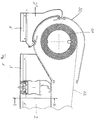
- Fig. 1 shows the arrangement of an awning on the invention Mounting profile 1 ', 1, comprising a mounted in an awning housing 50 Cloth shaft 51, from which the awning fabric 52 is unrolled.
- the awning housing 50 is fixed in a housing bracket 2 ', which in turn by means of Mounting profile 1 'on a building construction, not shown, such as conserveatory, is attached.
- By means of the fastening profile 1 are on the Construction continues to fasten guide rails 2, in which the Markisenausfahrprofil; where the front end of the awning is attached, movably guided.
- Fig. 2 Shown in Fig. 2 is a cross section through the inventive Fixing profile 1, with the attached guide rail 2 along the line II-II according to FIG. 1.
- the fastening profile 1 is formed by two upwardly directed side parts 10, 20 and a running between the two side parts lower cross member 30, wherein the profile 1 is made in two parts and the first profile part 15 of the first side part 10 and the cross member 30 and the second profile part 20 of the second side part 20 is formed.
- the side parts 10, 20 of the fastening profile. 1 have at their upper ends in each case a nose 11, 21, which in a Recess in the component to be fixed 2 (guide rail) engage and a projection 3, 4, engage behind the component 2 to be fixed.
- the lugs 11, 21 on the side parts 10, 20 and the projections 3, 4 at the zu fixing component 2 are each over the entire length of the fastening profile 1 and the component 2 to be fixed, so that thereby longitudinal grooves along the profile and along the component to be fixed, in each corresponding counterpart eino.
- the side part 20 has through-holes 22 transversely to the profile longitudinal direction, be screwed through the threaded bolt 24, which is against a support 17th supported on the first profile part 15.
- the second profile part 20 has a lower nose 23, which passes through a longitudinal groove is formed, which engages in a recess on the first profile part 15 and a Projection 16 on the first profile part 15 engages behind.
- the nose 23 on the second profile part 20 and the recess and the projection 16 on the first profile part 15 are over the entire profile length formed, this alternatively also sections can be trained.
- the lower cross member 30 has through holes, through the screws 31 are feasible and by means of which the fastening profile 1 on the not shown Building construction can be fastened directly or via intermediate parts.
- the fastening profile 1 has a cable guide 32 through which electrical Supply lines, for example, to lighting devices or similar, are feasible.
- the fastening profile 1 alternatively or cumulatively to those screwed into the through-threads 22 Threaded bolt 24 springs, in particular coil springs or leaf springs, which spread the side parts 10, 20 of the fastening profile 1.
- Threaded bolt 24 springs in particular coil springs or leaf springs, which spread the side parts 10, 20 of the fastening profile 1.
Landscapes
- Engineering & Computer Science (AREA)
- Architecture (AREA)
- Civil Engineering (AREA)
- Structural Engineering (AREA)
- Clamps And Clips (AREA)
- Building Awnings And Sunshades (AREA)
- Tents Or Canopies (AREA)
- Building Environments (AREA)
- Coupling Device And Connection With Printed Circuit (AREA)
- Auxiliary Devices For And Details Of Packaging Control (AREA)
- Paper (AREA)
Abstract
Description
- Fig. 1
- Eine Seitenansicht einer auf dem erfindungsgemäßen Befestigungsprofil montierten Markise, in die ein Schnitt durch das Befestigungsprofil und eine mittels des Profils fixierte Führungsschiene einer Markise eingezeichnet ist,
- Fig. 2
- einen Querschnitt des erfindungsgemäßen Befestigungsprofils nach Linie II-II nach Fig. 1.
Claims (15)
- Befestigungsprofil (1) zur Anbringung an Baukonstruktionen, insbesondere oberhalb von Bauten und Wintergärten, das der Befestigung eines Bauteiles (2) dient, insbesondere eines Markisengehäuses und/oder von Führungsschienen in oder auf denen ein Markisen-Ausfahrprofil verfahrbar geführt ist, dadurch gekennzeichnet, dass das Befestigungsprofil (1) zwei nach oben gerichtete Seitenteile (10, 20) und ein zwischen den beiden Seitenteilen verlaufendes unteres Querteil (30) aufweist, wobei die Seitenteile (10, 20) aufspreizbar sind, wodurch ein die Seitenteile (10, 20) übergreifendes Bauteil infolge der Spreizung durch Klemmung und/oder formschlüssige Verbindung befestigbar ist.
- Befestigungsprofil (1) nach Anspruch 1, dadurch gekennzeichnet, dass zumindest ein Seitenteil (10, 20) an seinem oberen Ende eine Nase (11, 21), die insbesondere durch eine Längsnut gebildet ist, oder einen Vorsprung aufweist, die/der in eine Ausnehmung oder Längsnut in dem zu fixierenden Bauteil (2) eingreift und/oder mit der/dem ein Vorsprung (3, 4) an dem zu fixierenden Bauteil (2) hintergreifbar ist.
- Befestigungsprofil (1) nach einem der vorherigen Ansprüche, dadurch gekennzeichnet, dass zumindest ein Seitenteil zumindest ein Durchgangsgewinde (22) quer zur Profillängsrichtung aufweist.
- Befestigungsprofil (1) nach Anspruch 3, dadurch gekennzeichnet, dass das Seitenteil zumindest einen Gewindebolzen (24) aufweist, der durch das Durchgangsgewinde (22) schraubbar ist und sich gegen ein Auflager abstützt.
- Befestigungsprofil (1) nach einem der vorherigen Ansprüche, dadurch gekennzeichnet, dass das Profil (1) zweiteilig ausgeführt ist, wobei das erste Profilteil (15) von dem ersten Seitenteil (10) und dem Querteil (30) und das zweite Profilteil (20) von dem zweiten Seitenteil (20) gebildet wird.
- Befestigungsprofil nach Anspruch 5, dadurch gekennzeichnet, dass das zweite Profilteil (20) eine untere Nase oder Vorsprung (23) aufweist, die insbesondere durch eine Längsnut gebildet ist, die in eine Ausnehmung oder Längsnut im ersten Profilteil (15) eingreift und/oder mit der ein Vorsprung (16) am ersten Profilteil (15) hintergreifbar ist.
- Befestigungsprofil (1) nach Anspruch 5 oder 6, dadurch gekennzeichnet, dass das zweite Proflteil (20) zumindest ein Durchgangsgewinde (22) quer zur Profillängsrichtung aufweist.
- Befestigungsprofil (1) nach Anspruch 7, dadurch gekennzeichnet, dass das zweite Profilteil (20) zumindest einen Gewindebolzen (24) aufweist, der durch das Durchgangsgewinde (22) schraubbar ist und sich gegen ein Auflager (17) am ersten Profilteil (15) abstützt.
- Befestigungsprofil (1) nach einem der Ansprüche 5 bis 8, dadurch gekennzeichnet, dass zwischen dem ersten (15) und dem zweiten Profilteil (20) zumindest eine Feder, insbesondere eine Schraubenfeder oder eine Blattfeder angeordnet ist, die sich insbesondere gegen ein Auflager (17) am ersten Profilteil (15) abstützt.
- Befestigungsprofil (1) nach einem der Ansprüche 1 bis 4, dadurch gekennzeichnet, dass das Profil (1) dreiteilig ausgeführt ist, wobei das erste Profilteil von dem ersten Seitenteil (10) und das zweite Profilteil von dem zweiten Seitenteil (20) und das dritte Profilteil von dem Querteil (30) gebildet wird.
- Befestigungsprofil (1) nach Anspruch 10, dadurch gekennzeichnet, dass die Seitenteile (10, 20) eine untere Nase oder Vorsprung aufweisen, die insbesondere durch eine Längsnut in dem Seitenteil gebildet ist, die in eine Ausnehmung oder Längsnut im Querteil (30) eingreifen und/oder mit denen jeweils ein Vorsprung am Querteil (30) hintergreifbar ist.
- Befestigungsprofil (1) nach Anspruch 10 oder 11, dadurch gekennzeichnet, dass zumindest zwischen einem Seitenteil und dem Querteil und/oder zwischen einem ersten Seitenteil und dem zweiten Seitenteil zumindest eine Feder, insbesondere eine Schraubenfeder oder eine Blattfeder, vorgesehen ist, die sich gegen ein Auflager abstützt.
- Befestigungsprofil (1) nach einem der vorherigen Ansprüche, dadurch gekennzeichnet, dass das Querteil (30) zumindest eine Durchgangsbohrung, insbesondere ein Langloch, aufweist, durch die eine Schraube (31) führbar ist mittels derer das Befestigungsprofil (1) direkt oder über Zwischenteile an der Baukonstruktion befestigbar ist.
- Befestigungsprofil (1) nach einem der vorherigen Ansprüche, dadurch gekennzeichnet, dass das Befestigungsprofil (1) in Längsrichtung zumindest eine Kabelführung (32) und/oder zumindest einen Kabelkanal aufweist.
- Befestigungsprofil (1) nach einem der Ansprüche 5 bis 14, dadurch gekennzeichnet, dass Mittel vorgesehen sind, die ein erstes Profilteil von zumindest einem zweiten Profilteil elektrisch isolieren, wobei zumindest ein Profilteil insbesondere aus einem elektrisch leitenden Werkstoff besteht.
Applications Claiming Priority (2)
| Application Number | Priority Date | Filing Date | Title |
|---|---|---|---|
| DE10357599A DE10357599A1 (de) | 2003-12-08 | 2003-12-08 | Befestiungsprofil |
| DE10357599 | 2003-12-08 |
Publications (3)
| Publication Number | Publication Date |
|---|---|
| EP1541776A2 true EP1541776A2 (de) | 2005-06-15 |
| EP1541776A3 EP1541776A3 (de) | 2008-01-23 |
| EP1541776B1 EP1541776B1 (de) | 2010-09-08 |
Family
ID=34258769
Family Applications (1)
| Application Number | Title | Priority Date | Filing Date |
|---|---|---|---|
| EP04024595A Expired - Lifetime EP1541776B1 (de) | 2003-12-08 | 2004-10-15 | Befestigungsprofil |
Country Status (3)
| Country | Link |
|---|---|
| EP (1) | EP1541776B1 (de) |
| AT (1) | ATE480681T1 (de) |
| DE (3) | DE10357599A1 (de) |
Cited By (2)
| Publication number | Priority date | Publication date | Assignee | Title |
|---|---|---|---|---|
| DE102004061625A1 (de) * | 2004-12-17 | 2006-07-06 | Weinor Dieter Weiermann Gmbh & Co. | Tragrohrmarkise |
| GB2468404A (en) * | 2009-03-03 | 2010-09-08 | Simon Claxton | Awning for a conservatory |
Families Citing this family (3)
| Publication number | Priority date | Publication date | Assignee | Title |
|---|---|---|---|---|
| TR200900024A2 (tr) * | 2009-01-03 | 2010-03-22 | Skan İç Ve Diş Ti̇c. İnş. Elektroni̇k Teksti̇l Gida Ve Maden San. A.Ş. | Aydınlatmalı raylı tentelerde kullanılan kablo koruma kanalı. |
| DE102013013007A1 (de) * | 2013-08-06 | 2015-02-12 | Weinor Gmbh & Co. Kg | Profil aus Basisprofil und Deckelprofil |
| DE202020103482U1 (de) * | 2020-06-17 | 2020-09-02 | Helge Weiß | Markisengestell und Markise |
Citations (2)
| Publication number | Priority date | Publication date | Assignee | Title |
|---|---|---|---|---|
| DE29622209U1 (de) | 1996-12-20 | 1997-02-13 | Hueppe Form Sonnenschutz | Markisenkonsole |
| DE29905346U1 (de) | 1999-03-24 | 1999-06-02 | Weiß, Helge, 24626 Groß Kummerfeld | Konsole zur Befestigung des Gehäuses von Markisen an einer Wand |
Family Cites Families (5)
| Publication number | Priority date | Publication date | Assignee | Title |
|---|---|---|---|---|
| DE29702765U1 (de) * | 1997-02-17 | 1998-06-10 | Schoene Kg Robert | Kastenmarkise |
| DE19823853A1 (de) * | 1998-05-28 | 1998-11-05 | Werner Dipl Ing Dietzsch | Seitenführungsschienen |
| DE19908053A1 (de) * | 1999-02-25 | 2000-09-28 | Roedelbronn Gmbh | Tuchwellenlager |
| DE10061820A1 (de) * | 2000-12-12 | 2002-06-13 | Schmitz Werke | Gelenkarm-Markise |
| DE10150707C5 (de) * | 2001-10-13 | 2007-11-22 | Erhardt Markisenbau Gmbh | Vorrichtung zur Aufnahme eines Lauforgans |
-
2003
- 2003-12-08 DE DE10357599A patent/DE10357599A1/de not_active Withdrawn
-
2004
- 2004-10-15 DE DE502004011635T patent/DE502004011635D1/de not_active Expired - Lifetime
- 2004-10-15 EP EP04024595A patent/EP1541776B1/de not_active Expired - Lifetime
- 2004-10-15 AT AT04024595T patent/ATE480681T1/de active
- 2004-12-08 DE DE202004019062U patent/DE202004019062U1/de not_active Expired - Lifetime
Patent Citations (2)
| Publication number | Priority date | Publication date | Assignee | Title |
|---|---|---|---|---|
| DE29622209U1 (de) | 1996-12-20 | 1997-02-13 | Hueppe Form Sonnenschutz | Markisenkonsole |
| DE29905346U1 (de) | 1999-03-24 | 1999-06-02 | Weiß, Helge, 24626 Groß Kummerfeld | Konsole zur Befestigung des Gehäuses von Markisen an einer Wand |
Cited By (2)
| Publication number | Priority date | Publication date | Assignee | Title |
|---|---|---|---|---|
| DE102004061625A1 (de) * | 2004-12-17 | 2006-07-06 | Weinor Dieter Weiermann Gmbh & Co. | Tragrohrmarkise |
| GB2468404A (en) * | 2009-03-03 | 2010-09-08 | Simon Claxton | Awning for a conservatory |
Also Published As
| Publication number | Publication date |
|---|---|
| DE10357599A1 (de) | 2005-06-30 |
| EP1541776A3 (de) | 2008-01-23 |
| DE202004019062U1 (de) | 2005-03-03 |
| ATE480681T1 (de) | 2010-09-15 |
| EP1541776B1 (de) | 2010-09-08 |
| DE502004011635D1 (de) | 2010-10-21 |
Similar Documents
| Publication | Publication Date | Title |
|---|---|---|
| EP1197624B1 (de) | Befestigungsvorrichtung für eine Schiene | |
| WO2002038897A1 (de) | Büchse für die befestigung eines beschlagteils an einem mit einem vorgesetzten profilteil versehenen hohlprofil | |
| EP3241974B1 (de) | Anordnung für eine dichtung, insbesondere für eine auflaufdichtung oder für eine sich selbsttätig absenkende bodendichtung für türen | |
| DE69612251T2 (de) | Haltevorrichtung für ein, gegenüber der vertikalen Fassade einer Vorhängewand eines Gebäudes oder ähnlichen Konstruktion, freitragendes Element | |
| EP1541776B1 (de) | Befestigungsprofil | |
| AT522794B1 (de) | Adapter zur Halterung von Fassadenelementen | |
| EP1439269A1 (de) | Verbinder für die Befestigung von Montageprofilen der Sanitärtechnik sowie Traggestell mit einem solchen Verbinder | |
| AT408561B (de) | Schutzzaun | |
| EP1898041B1 (de) | Vorrichtung und Verfahren zum Befestigen von Aufsatzelementen auf bauseitigen Rahmensystemen | |
| EP2320022B1 (de) | Scharnier für ein Insekten- und/oder Pollenschutzgitter | |
| DE102007051058B4 (de) | Befestigungsklammer und System zum Erstellen von Aufbauten | |
| DE202007008150U1 (de) | Befestigungsvorrichtung für Solarmodule | |
| DE202016105087U1 (de) | Halteschiene für einen französischen Balkon sowie Haltevorrichtung und Anordnung dafür | |
| EP1811121B1 (de) | Wellenlagerung für eine Senkrechtmarkise | |
| DE29709941U1 (de) | Beschlag zur Befestigung eines Tür- oder Fensterrahmens | |
| EP2182157B1 (de) | Blende für einen Spalt zwischen einer Tür- oder Torzarge und Laibung | |
| DE29708747U1 (de) | Fenster-, Türanordnung o.dgl. | |
| EP0348731B1 (de) | Stahlrohrmast mit einsteckbar befestigter Tragschiene für einen Armaturblock | |
| DE20203512U1 (de) | Rahmensystemanordnung | |
| DE19933252B4 (de) | Trennwandsystem | |
| EP0653540A2 (de) | Fensterbank | |
| DE102023000634A1 (de) | Geländertragprofil | |
| DE202012011985U1 (de) | Tor | |
| DE202020006130U1 (de) | Führungsschienenanordnung für eine Pfosten-Riegel-Fassade und mit solchen Führungsschienenanordnungen ausgestattete Pfosten-Riegel-Fassade | |
| DE10315774B3 (de) | Profil für eine Versorgungseinheit |
Legal Events
| Date | Code | Title | Description |
|---|---|---|---|
| PUAI | Public reference made under article 153(3) epc to a published international application that has entered the european phase |
Free format text: ORIGINAL CODE: 0009012 |
|
| AK | Designated contracting states |
Kind code of ref document: A2 Designated state(s): AT BE BG CH CY CZ DE DK EE ES FI FR GB GR HU IE IT LI LU MC NL PL PT RO SE SI SK TR |
|
| AX | Request for extension of the european patent |
Extension state: AL HR LT LV MK |
|
| PUAL | Search report despatched |
Free format text: ORIGINAL CODE: 0009013 |
|
| AK | Designated contracting states |
Kind code of ref document: A3 Designated state(s): AT BE BG CH CY CZ DE DK EE ES FI FR GB GR HU IE IT LI LU MC NL PL PT RO SE SI SK TR |
|
| AX | Request for extension of the european patent |
Extension state: AL HR LT LV MK |
|
| 17P | Request for examination filed |
Effective date: 20080122 |
|
| AKX | Designation fees paid |
Designated state(s): AT BE BG CH CY CZ DE DK EE ES FI FR GB GR HU IE IT LI LU MC NL PL PT RO SE SI SK TR |
|
| RAP1 | Party data changed (applicant data changed or rights of an application transferred) |
Owner name: WEINOR GMBH & CO. KG |
|
| 17Q | First examination report despatched |
Effective date: 20090703 |
|
| GRAP | Despatch of communication of intention to grant a patent |
Free format text: ORIGINAL CODE: EPIDOSNIGR1 |
|
| GRAS | Grant fee paid |
Free format text: ORIGINAL CODE: EPIDOSNIGR3 |
|
| GRAA | (expected) grant |
Free format text: ORIGINAL CODE: 0009210 |
|
| AK | Designated contracting states |
Kind code of ref document: B1 Designated state(s): AT BE BG CH CY CZ DE DK EE ES FI FR GB GR HU IE IT LI LU MC NL PL PT RO SE SI SK TR |
|
| REG | Reference to a national code |
Ref country code: GB Ref legal event code: FG4D Free format text: NOT ENGLISH |
|
| REG | Reference to a national code |
Ref country code: CH Ref legal event code: EP |
|
| REG | Reference to a national code |
Ref country code: IE Ref legal event code: FG4D Free format text: LANGUAGE OF EP DOCUMENT: GERMAN |
|
| REG | Reference to a national code |
Ref country code: CH Ref legal event code: NV Representative=s name: VALIPAT / PATENTS.EU S.A. C/O GUINNARD SA |
|
| REF | Corresponds to: |
Ref document number: 502004011635 Country of ref document: DE Date of ref document: 20101021 Kind code of ref document: P |
|
| REG | Reference to a national code |
Ref country code: CH Ref legal event code: PK Free format text: DER VERTRETEREINTRAG VOM 04.10.2010 ERFOLGTE IRRTUEMLICH. |
|
| REG | Reference to a national code |
Ref country code: NL Ref legal event code: T3 |
|
| PG25 | Lapsed in a contracting state [announced via postgrant information from national office to epo] |
Ref country code: FI Free format text: LAPSE BECAUSE OF FAILURE TO SUBMIT A TRANSLATION OF THE DESCRIPTION OR TO PAY THE FEE WITHIN THE PRESCRIBED TIME-LIMIT Effective date: 20100908 |
|
| PG25 | Lapsed in a contracting state [announced via postgrant information from national office to epo] |
Ref country code: PL Free format text: LAPSE BECAUSE OF FAILURE TO SUBMIT A TRANSLATION OF THE DESCRIPTION OR TO PAY THE FEE WITHIN THE PRESCRIBED TIME-LIMIT Effective date: 20100908 Ref country code: CY Free format text: LAPSE BECAUSE OF FAILURE TO SUBMIT A TRANSLATION OF THE DESCRIPTION OR TO PAY THE FEE WITHIN THE PRESCRIBED TIME-LIMIT Effective date: 20100908 Ref country code: SI Free format text: LAPSE BECAUSE OF FAILURE TO SUBMIT A TRANSLATION OF THE DESCRIPTION OR TO PAY THE FEE WITHIN THE PRESCRIBED TIME-LIMIT Effective date: 20100908 |
|
| REG | Reference to a national code |
Ref country code: IE Ref legal event code: FD4D |
|
| PG25 | Lapsed in a contracting state [announced via postgrant information from national office to epo] |
Ref country code: GR Free format text: LAPSE BECAUSE OF FAILURE TO SUBMIT A TRANSLATION OF THE DESCRIPTION OR TO PAY THE FEE WITHIN THE PRESCRIBED TIME-LIMIT Effective date: 20101209 Ref country code: SE Free format text: LAPSE BECAUSE OF FAILURE TO SUBMIT A TRANSLATION OF THE DESCRIPTION OR TO PAY THE FEE WITHIN THE PRESCRIBED TIME-LIMIT Effective date: 20100908 |
|
| PG25 | Lapsed in a contracting state [announced via postgrant information from national office to epo] |
Ref country code: IE Free format text: LAPSE BECAUSE OF FAILURE TO SUBMIT A TRANSLATION OF THE DESCRIPTION OR TO PAY THE FEE WITHIN THE PRESCRIBED TIME-LIMIT Effective date: 20100908 |
|
| PG25 | Lapsed in a contracting state [announced via postgrant information from national office to epo] |
Ref country code: EE Free format text: LAPSE BECAUSE OF FAILURE TO SUBMIT A TRANSLATION OF THE DESCRIPTION OR TO PAY THE FEE WITHIN THE PRESCRIBED TIME-LIMIT Effective date: 20100908 Ref country code: RO Free format text: LAPSE BECAUSE OF FAILURE TO SUBMIT A TRANSLATION OF THE DESCRIPTION OR TO PAY THE FEE WITHIN THE PRESCRIBED TIME-LIMIT Effective date: 20100908 Ref country code: SK Free format text: LAPSE BECAUSE OF FAILURE TO SUBMIT A TRANSLATION OF THE DESCRIPTION OR TO PAY THE FEE WITHIN THE PRESCRIBED TIME-LIMIT Effective date: 20100908 Ref country code: CZ Free format text: LAPSE BECAUSE OF FAILURE TO SUBMIT A TRANSLATION OF THE DESCRIPTION OR TO PAY THE FEE WITHIN THE PRESCRIBED TIME-LIMIT Effective date: 20100908 Ref country code: MC Free format text: LAPSE BECAUSE OF NON-PAYMENT OF DUE FEES Effective date: 20101031 Ref country code: PT Free format text: LAPSE BECAUSE OF FAILURE TO SUBMIT A TRANSLATION OF THE DESCRIPTION OR TO PAY THE FEE WITHIN THE PRESCRIBED TIME-LIMIT Effective date: 20110110 |
|
| PG25 | Lapsed in a contracting state [announced via postgrant information from national office to epo] |
Ref country code: ES Free format text: LAPSE BECAUSE OF FAILURE TO SUBMIT A TRANSLATION OF THE DESCRIPTION OR TO PAY THE FEE WITHIN THE PRESCRIBED TIME-LIMIT Effective date: 20101219 |
|
| PLBE | No opposition filed within time limit |
Free format text: ORIGINAL CODE: 0009261 |
|
| STAA | Information on the status of an ep patent application or granted ep patent |
Free format text: STATUS: NO OPPOSITION FILED WITHIN TIME LIMIT |
|
| 26N | No opposition filed |
Effective date: 20110609 |
|
| PG25 | Lapsed in a contracting state [announced via postgrant information from national office to epo] |
Ref country code: DK Free format text: LAPSE BECAUSE OF FAILURE TO SUBMIT A TRANSLATION OF THE DESCRIPTION OR TO PAY THE FEE WITHIN THE PRESCRIBED TIME-LIMIT Effective date: 20100908 |
|
| REG | Reference to a national code |
Ref country code: DE Ref legal event code: R097 Ref document number: 502004011635 Country of ref document: DE Effective date: 20110609 |
|
| PG25 | Lapsed in a contracting state [announced via postgrant information from national office to epo] |
Ref country code: BG Free format text: LAPSE BECAUSE OF FAILURE TO SUBMIT A TRANSLATION OF THE DESCRIPTION OR TO PAY THE FEE WITHIN THE PRESCRIBED TIME-LIMIT Effective date: 20100908 Ref country code: HU Free format text: LAPSE BECAUSE OF FAILURE TO SUBMIT A TRANSLATION OF THE DESCRIPTION OR TO PAY THE FEE WITHIN THE PRESCRIBED TIME-LIMIT Effective date: 20110309 Ref country code: LU Free format text: LAPSE BECAUSE OF NON-PAYMENT OF DUE FEES Effective date: 20101015 |
|
| PG25 | Lapsed in a contracting state [announced via postgrant information from national office to epo] |
Ref country code: TR Free format text: LAPSE BECAUSE OF FAILURE TO SUBMIT A TRANSLATION OF THE DESCRIPTION OR TO PAY THE FEE WITHIN THE PRESCRIBED TIME-LIMIT Effective date: 20100908 |
|
| PG25 | Lapsed in a contracting state [announced via postgrant information from national office to epo] |
Ref country code: BG Free format text: LAPSE BECAUSE OF FAILURE TO SUBMIT A TRANSLATION OF THE DESCRIPTION OR TO PAY THE FEE WITHIN THE PRESCRIBED TIME-LIMIT Effective date: 20101208 |
|
| REG | Reference to a national code |
Ref country code: FR Ref legal event code: PLFP Year of fee payment: 12 |
|
| REG | Reference to a national code |
Ref country code: FR Ref legal event code: PLFP Year of fee payment: 13 |
|
| REG | Reference to a national code |
Ref country code: FR Ref legal event code: PLFP Year of fee payment: 14 |
|
| REG | Reference to a national code |
Ref country code: FR Ref legal event code: PLFP Year of fee payment: 15 |
|
| PGFP | Annual fee paid to national office [announced via postgrant information from national office to epo] |
Ref country code: NL Payment date: 20181022 Year of fee payment: 15 |
|
| PGFP | Annual fee paid to national office [announced via postgrant information from national office to epo] |
Ref country code: SE Payment date: 20181126 Year of fee payment: 10 |
|
| PGFP | Annual fee paid to national office [announced via postgrant information from national office to epo] |
Ref country code: GB Payment date: 20181025 Year of fee payment: 15 Ref country code: IT Payment date: 20181022 Year of fee payment: 15 Ref country code: BE Payment date: 20181022 Year of fee payment: 15 Ref country code: CH Payment date: 20181025 Year of fee payment: 15 Ref country code: FR Payment date: 20181023 Year of fee payment: 15 |
|
| PGFP | Annual fee paid to national office [announced via postgrant information from national office to epo] |
Ref country code: DE Payment date: 20191031 Year of fee payment: 16 |
|
| REG | Reference to a national code |
Ref country code: CH Ref legal event code: PL |
|
| REG | Reference to a national code |
Ref country code: NL Ref legal event code: MM Effective date: 20191101 |
|
| PG25 | Lapsed in a contracting state [announced via postgrant information from national office to epo] |
Ref country code: LI Free format text: LAPSE BECAUSE OF NON-PAYMENT OF DUE FEES Effective date: 20191031 Ref country code: CH Free format text: LAPSE BECAUSE OF NON-PAYMENT OF DUE FEES Effective date: 20191031 |
|
| REG | Reference to a national code |
Ref country code: BE Ref legal event code: MM Effective date: 20191031 |
|
| REG | Reference to a national code |
Ref country code: AT Ref legal event code: MM01 Ref document number: 480681 Country of ref document: AT Kind code of ref document: T Effective date: 20191015 |
|
| PG25 | Lapsed in a contracting state [announced via postgrant information from national office to epo] |
Ref country code: BE Free format text: LAPSE BECAUSE OF NON-PAYMENT OF DUE FEES Effective date: 20191031 Ref country code: NL Free format text: LAPSE BECAUSE OF NON-PAYMENT OF DUE FEES Effective date: 20191101 |
|
| GBPC | Gb: european patent ceased through non-payment of renewal fee |
Effective date: 20191015 |
|
| PG25 | Lapsed in a contracting state [announced via postgrant information from national office to epo] |
Ref country code: GB Free format text: LAPSE BECAUSE OF NON-PAYMENT OF DUE FEES Effective date: 20191015 Ref country code: FR Free format text: LAPSE BECAUSE OF NON-PAYMENT OF DUE FEES Effective date: 20191031 Ref country code: IT Free format text: LAPSE BECAUSE OF NON-PAYMENT OF DUE FEES Effective date: 20191015 |
|
| PG25 | Lapsed in a contracting state [announced via postgrant information from national office to epo] |
Ref country code: AT Free format text: LAPSE BECAUSE OF NON-PAYMENT OF DUE FEES Effective date: 20191015 |
|
| REG | Reference to a national code |
Ref country code: DE Ref legal event code: R119 Ref document number: 502004011635 Country of ref document: DE |
|
| PG25 | Lapsed in a contracting state [announced via postgrant information from national office to epo] |
Ref country code: DE Free format text: LAPSE BECAUSE OF NON-PAYMENT OF DUE FEES Effective date: 20210501 |