EP1541840A2 - Procédé de fonctionnement d'un actionneur pour soupape d'injection et soupape d'injection - Google Patents
Procédé de fonctionnement d'un actionneur pour soupape d'injection et soupape d'injection Download PDFInfo
- Publication number
- EP1541840A2 EP1541840A2 EP04106369A EP04106369A EP1541840A2 EP 1541840 A2 EP1541840 A2 EP 1541840A2 EP 04106369 A EP04106369 A EP 04106369A EP 04106369 A EP04106369 A EP 04106369A EP 1541840 A2 EP1541840 A2 EP 1541840A2
- Authority
- EP
- European Patent Office
- Prior art keywords
- actuator
- injection
- operating method
- determination
- voltage
- Prior art date
- Legal status (The legal status is an assumption and is not a legal conclusion. Google has not performed a legal analysis and makes no representation as to the accuracy of the status listed.)
- Withdrawn
Links
- 238000002347 injection Methods 0.000 title claims abstract description 65
- 239000007924 injection Substances 0.000 title claims abstract description 65
- 238000000034 method Methods 0.000 title claims abstract description 13
- 238000011017 operating method Methods 0.000 claims description 29
- 230000002123 temporal effect Effects 0.000 claims description 18
- 239000000446 fuel Substances 0.000 claims description 14
- 230000008569 process Effects 0.000 claims description 11
- 238000002485 combustion reaction Methods 0.000 claims description 5
- 238000007599 discharging Methods 0.000 claims description 3
- 238000001514 detection method Methods 0.000 claims description 2
- 230000010355 oscillation Effects 0.000 claims description 2
- 230000004913 activation Effects 0.000 description 2
- 238000010586 diagram Methods 0.000 description 2
- 238000005259 measurement Methods 0.000 description 2
- 235000001674 Agaricus brunnescens Nutrition 0.000 description 1
- 230000005526 G1 to G0 transition Effects 0.000 description 1
- 230000009471 action Effects 0.000 description 1
- 238000011161 development Methods 0.000 description 1
- 230000018109 developmental process Effects 0.000 description 1
- 238000012986 modification Methods 0.000 description 1
- 230000004048 modification Effects 0.000 description 1
- 230000004044 response Effects 0.000 description 1
- 238000000926 separation method Methods 0.000 description 1
Images


Classifications
-
- F—MECHANICAL ENGINEERING; LIGHTING; HEATING; WEAPONS; BLASTING
- F02—COMBUSTION ENGINES; HOT-GAS OR COMBUSTION-PRODUCT ENGINE PLANTS
- F02D—CONTROLLING COMBUSTION ENGINES
- F02D41/00—Electrical control of supply of combustible mixture or its constituents
- F02D41/20—Output circuits, e.g. for controlling currents in command coils
- F02D41/2096—Output circuits, e.g. for controlling currents in command coils for controlling piezoelectric injectors
-
- F—MECHANICAL ENGINEERING; LIGHTING; HEATING; WEAPONS; BLASTING
- F02—COMBUSTION ENGINES; HOT-GAS OR COMBUSTION-PRODUCT ENGINE PLANTS
- F02D—CONTROLLING COMBUSTION ENGINES
- F02D41/00—Electrical control of supply of combustible mixture or its constituents
- F02D41/20—Output circuits, e.g. for controlling currents in command coils
- F02D2041/202—Output circuits, e.g. for controlling currents in command coils characterised by the control of the circuit
- F02D2041/2034—Control of the current gradient
-
- F—MECHANICAL ENGINEERING; LIGHTING; HEATING; WEAPONS; BLASTING
- F02—COMBUSTION ENGINES; HOT-GAS OR COMBUSTION-PRODUCT ENGINE PLANTS
- F02D—CONTROLLING COMBUSTION ENGINES
- F02D41/00—Electrical control of supply of combustible mixture or its constituents
- F02D41/20—Output circuits, e.g. for controlling currents in command coils
- F02D2041/202—Output circuits, e.g. for controlling currents in command coils characterised by the control of the circuit
- F02D2041/2051—Output circuits, e.g. for controlling currents in command coils characterised by the control of the circuit using voltage control
-
- F—MECHANICAL ENGINEERING; LIGHTING; HEATING; WEAPONS; BLASTING
- F02—COMBUSTION ENGINES; HOT-GAS OR COMBUSTION-PRODUCT ENGINE PLANTS
- F02D—CONTROLLING COMBUSTION ENGINES
- F02D41/00—Electrical control of supply of combustible mixture or its constituents
- F02D41/20—Output circuits, e.g. for controlling currents in command coils
- F02D2041/202—Output circuits, e.g. for controlling currents in command coils characterised by the control of the circuit
- F02D2041/2055—Output circuits, e.g. for controlling currents in command coils characterised by the control of the circuit with means for determining actual opening or closing time
-
- F—MECHANICAL ENGINEERING; LIGHTING; HEATING; WEAPONS; BLASTING
- F02—COMBUSTION ENGINES; HOT-GAS OR COMBUSTION-PRODUCT ENGINE PLANTS
- F02D—CONTROLLING COMBUSTION ENGINES
- F02D41/00—Electrical control of supply of combustible mixture or its constituents
- F02D41/20—Output circuits, e.g. for controlling currents in command coils
- F02D2041/202—Output circuits, e.g. for controlling currents in command coils characterised by the control of the circuit
- F02D2041/2058—Output circuits, e.g. for controlling currents in command coils characterised by the control of the circuit using information of the actual current value
-
- F—MECHANICAL ENGINEERING; LIGHTING; HEATING; WEAPONS; BLASTING
- F02—COMBUSTION ENGINES; HOT-GAS OR COMBUSTION-PRODUCT ENGINE PLANTS
- F02D—CONTROLLING COMBUSTION ENGINES
- F02D41/00—Electrical control of supply of combustible mixture or its constituents
- F02D41/30—Controlling fuel injection
- F02D41/38—Controlling fuel injection of the high pressure type
- F02D41/40—Controlling fuel injection of the high pressure type with means for controlling injection timing or duration
- F02D41/401—Controlling injection timing
Definitions
- the invention relates to an operating method for an actuator an injection valve of an internal combustion engine and an injection valve.
- the mechanical drive of an injector in an injection system for an internal combustion engine serves.
- the actuator is not only the mechanical Actuation of the injector used, but also serves as a sensor for determining the valve position of the Injector.
- the actuator voltage not only from the electrical Charge of the actuator depends, but also by the on the actor acting force is affected, in turn depends on the valve position. Depending on the time course of the measured actuator voltage is therefore determined in this operating procedure, the start of injection.
- a disadvantage of this known operating method for a Actuator is the improvable accuracy in the Determination of the start of injection.
- the invention is therefore the object of the above to the known operating method described above improve the accuracy in determining the start of injection is improved.
- This task is characterized by the characteristics of independent features solved.
- the invention comprises the general technical teaching which temporal position of at least one inflection point of the voltage curve to determine and an injection size of interest, such as the start of injection, depending on it to determine.
- the actuator voltage increases at the beginning of an injection process due to the charge initially continuously until the Piezo actuator the valve body of the injector from his Valve seat lifts.
- the nozzle needle only contributes so long to the increase of the actuator voltage until she has reached her final position. Subsequently then the actuator voltage drops back to a stationary one Value down, in which in the control room of the injector There is equilibrium between inlet and outlet.
- a turning point in the voltage curve determined in order to derive the start of injection.
- the determination of a turning point instead of a local one Maximums or a local minimum is metrological safer, since local minima or maxima are also superimposed Interference signals can be generated.
- another turning point of Current curve determined to the start of injection in dependence to determine the timing of both turning points.
- a third inflection point for the determination the start of injection or another interest Injection size is used, the beginning of injection or the injection variable of interest depending determined by the timing of the third inflection point becomes.
- the third inflection point around the turning point of the voltage curve between the first local maximum and the first local minimum.
- the temporal Location of local maxima and / or minima of the actuator voltage for the determination of the injection quantity of interest used become.
- the measured variables are preferably for the determination of the injection quantity of interest used, which occur relatively late, so for example the second local maximum of the actuator voltage and the two neighboring turning points.
- the measured variables that occur relatively early ie for example, the temporal location of the local minimum of Actuator voltage or the previous inflection point.
- the actuator becomes the completion of an injection process shorted, resulting in a complete discharge can lead the piezoelectric actuator, while still a determination the valve position is possible, as described in detail becomes.
- the invention therefore preferably provides that the Aktorstrom is detected in the short-circuited state to it Draw conclusions about the valve position.
- the piezoelectric actuator is discharged very quickly during short-circuiting and thereby shortened rapidly.
- the in normal operation the valve body of the injector acting end face
- the piezoelectric actuator is accelerated faster than the valve body itself, what the adhesion between the actor and influenced the valve body and even to a break of the frictional connection can lead.
- the valve body Upon impact of the valve body on the valve seat, the valve body then presses elastically in the valve seat and meets again on the ahead Piezoelectric actuator on, so that the piezoelectric actuator due the pulse-like pressure action through the valve body a Current pulse outputs.
- the operating method according to the invention is therefore preferably after shorting the temporal position a current pulse detected and the end of injection in dependence determined by the timing of the current pulse.
- a current pulse detected and the end of injection in dependence determined by the timing of the current pulse are read, but are also other types the determination of the end of injection as a function of temporal position of the current pulse possible.
- the measurement of the actuator current for detection takes place the current pulse preferably within a predetermined Time window after short-circuiting the actuator. This is advantageous because the timing of the current pulse after the short-circuiting of the actuator is roughly known, so that an accurate and therefore expensive current measurement only within of the time window of interest is required.
- the actuator before the short-circuiting preferably first defined discharged, to prevent overloading.
- a defined Discharge for example, with a predetermined time constant done, for example, by a resistor can be set in the discharge circuit of the actuator.
- the defined discharge of the actuator before the short-circuiting takes place preferably up to a fraction of the maximum stress or maximum charge of the actuator, so that in the subsequent Short circuiting of the actuator only a relatively small Energy must be dissipated.
- control unit shown in Figure 1 of an injector a Injection system for an internal combustion engine is largely conventionally constructed and used to control a Nozzle needle 1, which is linearly displaceable in the control unit is stored and the fuel injection in dependence releases or locks from their position.
- the control unit consists of three stacked Modules 2.1-2.3, whereby through modules 2.1-2.3 a high-pressure channel 4 runs, over which the fuel to be injected is supplied.
- the high pressure passage 4 opens in the lower Module 2.3 in a cylindrical channel 5, via which the Fuel to be injected reaches the nozzle opening.
- annular channel. 6 arranged, which surrounds the nozzle needle 1 annular, wherein of the annular channel 6 on the high-pressure channel 4 opposite Side another channel branches off, via an inlet throttle 7 opens into a control chamber 8.
- the middle module 2.2 is a valve seat 9 and a slidably mounted valve body 10, wherein the valve body 10, depending on its position, the valve seat 9 releases or locks.
- valve body 10 is in this case by a spring 11 in the direction biased to the valve seat, leaving the valve body 10 without concerns of external forces seals the valve seat 9, so that no fuel escape from the control chamber 8 upwards can.
- a piezoelectric actuator 12 For the mechanical drive of the valve body 10 is a piezoelectric actuator 12 is provided, which has a bottom plate 13 and a Hubzapfen 14 on one at the top of the valve body 10th molded valve mushroom 15 presses.
- the piezoelectric actuator 12 can therefore the valve body 10 in response to the piezoelectric actuator Push out 12 applied electrical voltage from the valve seat 9, allowing fuel from the control chamber 8 through the Valve seat 9 and an outlet throttle, not shown can escape.
- FIGS 2a and 2b show a flow chart of the operating method according to the invention for the piezoelectric actuator 12 described.
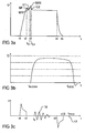
- the Actuator voltage between the times t1 and t2 in the in Figure 3a increases timing diagram. It lengthens the piezoelectric actuator 12 until the piezoelectric actuator 12 at the time t2 lifts the valve body 10 from the valve seat 9. From This time can then fuel from the control room. 8 escape upward through the valve seat 9 and over a drain throttle are removed. This initially leads to a pressure drop in the control chamber 8, resulting in a corresponding Voltage drop from the time t2 expresses.
- the pressure drop in the control room 8 also causes that the nozzle needle 1 moves upward while fuel displaced in the control chamber 8, resulting in an increase in pressure in the control room leads.
- the through the nozzle needle. 1 caused pressure increase in the control room 8 then leads up at time t3 again to an increase of the actuator voltage, until the nozzle needle 1 finally reaches its upper stop has and then no more fuel in the control room 8 more displaced.
- the actuator voltage no longer increases, but instead falls from the time t3 back on a stationary Value starting from a balance between inlet to the Control chamber 8 and drain from the control room 8 marked is.
- the actuator voltage is measured, wherein the voltage curve is evaluated to the start of injection to investigate.
- a first turning point G1 is determined, between the first local minimum and the second local maximum of the actuator voltage at the beginning of the injection process occurs.
- a second inflection point G2 is determined, which occurs after the absolute maximum of the actuator voltage. Between these two turning points G1, G2 is the time at which the nozzle needle 1 reaches its upper stop and thereby releases the injector. In the determination of the two turning points G1, G2 G2 are the points in time t, respectively G1 and t measured, at which the two turning points G1, G2 occur.
- time t BP of a further inflection point BP (breakpoint) is determined, which lies between the first local maximum and the first local minimum he actuator voltage, as can be seen in particular from FIGS. 3 a and 4.
- the temporal position t MIN or t MAX of the local minimum MIN and the maximum MAX is also measured.
- the actuator current shown in FIG. 3c carries out an oscillation 16, wherein the start t s and the phase position likewise allow a conclusion to be drawn as to the actual start of injection.
- the two variables t s and ⁇ s are also measured.
- the start of injection t BEGINN is then a function of the temporal position t G1 , t G2 , t BP of the three turning points G1, G2, BP, the temporal position t MIN , t MAX of the minimum MIN and the maximum MAX and in dependence the start t s of the vibrations 16 and the phase angle ⁇ s of the vibration 16 is calculated, wherein the time t BEGINN the injection process in dependence on these variables can also be read from a map.
- the piezoelectric actuator 12 is then until the time T5 controlled discharged until the piezoelectric actuator 12 then finally shorted at time t5.
- the injector does not close at the same time with the short-circuiting of the piezoelectric actuator 12, since the nozzle needle 1 previously has to take their lower stop point.
- the actuator current I is therefore measured after the time t5 of the short-circuiting of the piezoelectric actuator 12.
- the piezoelectric actuator 12 shortened during shorting very quickly, which affects the frictional connection between the valve body 10 and the piezoelectric actuator 12 and in extreme cases even lead to a separation of the piezoelectric actuator 12 of the valve body 10, since the movement of the Piezoaktors 12 of the movement of the valve body 10 leads.
- the valve body 10 presses elastically in the direction of the piezoactuator 12, which leads to a current pulse 17 when the valve body 10 strikes the piezoactuator 12.
- the temporal position t pulse of the current pulse 17 in this case allows a conclusion to the actual end of the injection process. In the context of the operating method according to the invention, therefore, in function of the timing pulse t of the current pulse 17 is the actual end t the end of the injection operation is calculated.
Landscapes
- Engineering & Computer Science (AREA)
- Chemical & Material Sciences (AREA)
- Combustion & Propulsion (AREA)
- Mechanical Engineering (AREA)
- General Engineering & Computer Science (AREA)
- Fuel-Injection Apparatus (AREA)
- Electrical Control Of Air Or Fuel Supplied To Internal-Combustion Engine (AREA)
Applications Claiming Priority (2)
| Application Number | Priority Date | Filing Date | Title |
|---|---|---|---|
| DE2003157481 DE10357481A1 (de) | 2003-12-09 | 2003-12-09 | Betriebsverfahren für einen Aktor eines Einspritzventils |
| DE10357481 | 2003-12-09 |
Publications (2)
| Publication Number | Publication Date |
|---|---|
| EP1541840A2 true EP1541840A2 (fr) | 2005-06-15 |
| EP1541840A3 EP1541840A3 (fr) | 2005-08-17 |
Family
ID=34485272
Family Applications (1)
| Application Number | Title | Priority Date | Filing Date |
|---|---|---|---|
| EP04106369A Withdrawn EP1541840A3 (fr) | 2003-12-09 | 2004-12-07 | Procédé de fonctionnement d'un actionneur pour soupape d'injection et soupape d'injection |
Country Status (3)
| Country | Link |
|---|---|
| EP (1) | EP1541840A3 (fr) |
| DE (1) | DE10357481A1 (fr) |
| WO (1) | WO2005059338A1 (fr) |
Cited By (4)
| Publication number | Priority date | Publication date | Assignee | Title |
|---|---|---|---|---|
| WO2005119038A1 (fr) * | 2004-06-03 | 2005-12-15 | Siemens Aktiengesellschaft | Procede et dispositif pour commander une soupape d'injection |
| WO2007107484A1 (fr) * | 2006-03-22 | 2007-09-27 | Robert Bosch Gmbh | Procede de determination de la tension d'ouverture d'un injecteur piezoelectrique |
| WO2010121889A1 (fr) * | 2009-04-21 | 2010-10-28 | Continental Automotive Gmbh | Procédé et dispositif de détermination d'une pression dans un accumulateur haute pression |
| CN105545512A (zh) * | 2014-10-24 | 2016-05-04 | 罗伯特·博世有限公司 | 用于对燃料喷射器的磁阀通电的方法 |
Families Citing this family (1)
| Publication number | Priority date | Publication date | Assignee | Title |
|---|---|---|---|---|
| DE102005040533B4 (de) * | 2005-08-26 | 2008-05-21 | Siemens Ag | Verfahren und Vorrichtung zum Erkennen eines Erreichens eines maximalen Öffnungszustands oder Schließzustands eines Ventils |
Citations (1)
| Publication number | Priority date | Publication date | Assignee | Title |
|---|---|---|---|---|
| DE19930309A1 (de) | 1999-07-01 | 2001-01-11 | Siemens Ag | Verfahren und Vorrichtung zur Regelung der Einspritzmenge bei einem Kraftstoffeinspritzventil mit Piezoelement-Aktor |
Family Cites Families (9)
| Publication number | Priority date | Publication date | Assignee | Title |
|---|---|---|---|---|
| DE2805175A1 (de) * | 1978-02-08 | 1979-08-09 | Bosch Gmbh Robert | Einrichtung zum erfassen des spritzbeginns eines einspritzventils |
| DE3118425A1 (de) * | 1981-05-09 | 1982-12-09 | Robert Bosch Gmbh, 7000 Stuttgart | Einrichtung zum erfassen der den brennraeumen eines dieselmotors zugefuehrten kraftstoffmenge |
| DE4011217A1 (de) * | 1990-04-06 | 1991-10-10 | Lucas Ind Plc | Verfahren zum ansteuern eines magnetventils einer schlupf-regelanlage |
| US6253736B1 (en) * | 1999-08-10 | 2001-07-03 | Cummins Engine Company, Inc. | Fuel injector nozzle assembly with feedback control |
| US6420817B1 (en) * | 2000-02-11 | 2002-07-16 | Delphi Technologies, Inc. | Method for detecting injection events in a piezoelectric actuated fuel injector |
| DE50009868D1 (de) * | 2000-07-01 | 2005-04-28 | Bosch Gmbh Robert | Piezoelektrischer Aktor eines Einspritzventils sowie Kraftstoffeinspritzsystem |
| DE10143501C1 (de) * | 2001-09-05 | 2003-05-28 | Siemens Ag | Verfahren zum Ansteuern eines piezobetriebenen Kraftstoff-Einspritzventils |
| WO2003081007A1 (fr) * | 2002-03-27 | 2003-10-02 | Siemens Aktiengesellschaft | Procede et dispositif de detection du moment d'impact du pointeau d'une soupape de commande piezoelectrique |
| US6748928B2 (en) * | 2002-04-26 | 2004-06-15 | Caterpillar Inc | In-chassis determination of fuel injector performance |
-
2003
- 2003-12-09 DE DE2003157481 patent/DE10357481A1/de not_active Ceased
-
2004
- 2004-11-30 WO PCT/EP2004/053170 patent/WO2005059338A1/fr not_active Ceased
- 2004-12-07 EP EP04106369A patent/EP1541840A3/fr not_active Withdrawn
Patent Citations (1)
| Publication number | Priority date | Publication date | Assignee | Title |
|---|---|---|---|---|
| DE19930309A1 (de) | 1999-07-01 | 2001-01-11 | Siemens Ag | Verfahren und Vorrichtung zur Regelung der Einspritzmenge bei einem Kraftstoffeinspritzventil mit Piezoelement-Aktor |
Cited By (9)
| Publication number | Priority date | Publication date | Assignee | Title |
|---|---|---|---|---|
| WO2005119038A1 (fr) * | 2004-06-03 | 2005-12-15 | Siemens Aktiengesellschaft | Procede et dispositif pour commander une soupape d'injection |
| WO2007107484A1 (fr) * | 2006-03-22 | 2007-09-27 | Robert Bosch Gmbh | Procede de determination de la tension d'ouverture d'un injecteur piezoelectrique |
| JP2009530538A (ja) * | 2006-03-22 | 2009-08-27 | ローベルト ボツシユ ゲゼルシヤフト ミツト ベシユレンクテル ハフツング | 圧電インジェクタの開放電圧を確定するための方法 |
| WO2010121889A1 (fr) * | 2009-04-21 | 2010-10-28 | Continental Automotive Gmbh | Procédé et dispositif de détermination d'une pression dans un accumulateur haute pression |
| CN102414425A (zh) * | 2009-04-21 | 2012-04-11 | 欧陆汽车有限责任公司 | 用于确定高压蓄压器中的压力的方法和装置 |
| CN102414425B (zh) * | 2009-04-21 | 2014-03-26 | 大陆汽车有限公司 | 用于确定高压蓄压器中的压力的方法和装置 |
| US8726885B2 (en) | 2009-04-21 | 2014-05-20 | Continental Automotive Gmbh | Method and device for determining a pressure in a high-pressure accumulator |
| CN105545512A (zh) * | 2014-10-24 | 2016-05-04 | 罗伯特·博世有限公司 | 用于对燃料喷射器的磁阀通电的方法 |
| CN105545512B (zh) * | 2014-10-24 | 2021-06-18 | 罗伯特·博世有限公司 | 用于对燃料喷射器的磁阀通电的方法 |
Also Published As
| Publication number | Publication date |
|---|---|
| WO2005059338A1 (fr) | 2005-06-30 |
| DE10357481A1 (de) | 2005-07-14 |
| EP1541840A3 (fr) | 2005-08-17 |
Similar Documents
| Publication | Publication Date | Title |
|---|---|---|
| DE10024662B4 (de) | Verfahren zum Betreiben eines Einspritzventils | |
| DE102008023373B4 (de) | Verfahren zum Steuern eines Einspritzventils, Kraftstoff-Einspritzanlage und Verbrennungsmotor | |
| DE112011101723B4 (de) | Piezoelektrisches Kraftstoffeinspritzdüsensystem, Verfahren zum Schätzen von Zeitpunktcharakteristika eines Kraftstoffeinspritzereignisses | |
| DE10356858B4 (de) | Betriebsverfahren für einen Aktor eines Einspritzventils und zugehörige Vorrichtung | |
| DE10319530B4 (de) | Verfahren und Vorrichtung zur Überwachung eines elektromechanischen Aktors | |
| WO2011064248A1 (fr) | Procédé de classification d'un injecteur, procédé d'étalonnage d'un diagramme caractéristique d'un injecteur et dispositif banc d'essai pour un injecteur | |
| EP1613851B1 (fr) | Procede pour determiner la tension d'amorcage individuelle d'un element piezo-electrique | |
| EP1541840A2 (fr) | Procédé de fonctionnement d'un actionneur pour soupape d'injection et soupape d'injection | |
| EP1430207B1 (fr) | Procede et dispositif de commande d'un consommateur electro-magnetique | |
| EP1692383B1 (fr) | Mode de fonctionnement d'un actionneur de soupape d'injection | |
| DE10349307B3 (de) | Diagnoseverfahren für einen elektromechanischen Aktor | |
| DE102016217415B4 (de) | Verfahren und Vorrichtung zum Kalibrieren von Kraftstoffinjektoren mit Leerhub | |
| WO2007104770A1 (fr) | Procédé et dispositif d'étalonnage d'un actionneur piézo-électrique | |
| DE102006048979B4 (de) | Verfahren und Einspritzsystem zum Einspsritzen eines Fluids | |
| DE19843621A1 (de) | Entladeschaltung für ein kapazitives Stellglied | |
| DE69030385T2 (de) | Vorrichtung zur regelung der voreinspritzung | |
| DE102005046933B4 (de) | Verfahren zum Ansteuern eines piezobetätigten Einspritzventils | |
| DE102004029906B4 (de) | Verfahren und Vorrichtung zum Steuern eines Einspritzventils und Computerprogramm | |
| DE102016206476B3 (de) | Verfahren zum Betreiben eines diesel-common-rail-piezobetriebenen Servoinjektors und Kraftfahrzeug | |
| EP1718854B1 (fr) | Procede et dispositif pour determiner les flancs de charge d'un actionneur piezo-electrique | |
| EP3347584B1 (fr) | Procédé de détection pour la détection d'une dimension d'un interstice entre un module de soupape d'injection et un empilement piézoélectrique, ainsi que procédé de commande pour la commande d'une unité d'actionneur dans un empilement piézoélectrique | |
| DE102016203822A1 (de) | Kraftstoffeinspritzventil | |
| DE102015208436A1 (de) | Überwachungsverfahren und Überwachungsvorrichtung zur Überwachung eines Füllvorgangs einer Injektoranordnung mit einem Kraftstoff und Befüllungsverfahren zum Befüllen einer Injektoranordnung | |
| DE102004052690B4 (de) | Treiber- und Auswerteeinrichtung für ein Einspritzventil,Verfahren und Vorrichtung zum Steuern eines Einspritzventils und Computerprogramm | |
| DE102018205540A1 (de) | Verfahren zur Ermittlung eines Ankerhubs eines Steuerventils und zum Betreiben des Steuerventils |
Legal Events
| Date | Code | Title | Description |
|---|---|---|---|
| PUAI | Public reference made under article 153(3) epc to a published international application that has entered the european phase |
Free format text: ORIGINAL CODE: 0009012 |
|
| AK | Designated contracting states |
Kind code of ref document: A2 Designated state(s): AT BE BG CH CY CZ DE DK EE ES FI FR GB GR HU IE IS IT LI LT LU MC NL PL PT RO SE SI SK TR |
|
| AX | Request for extension of the european patent |
Extension state: AL BA HR LV MK YU |
|
| PUAL | Search report despatched |
Free format text: ORIGINAL CODE: 0009013 |
|
| AK | Designated contracting states |
Kind code of ref document: A3 Designated state(s): AT BE BG CH CY CZ DE DK EE ES FI FR GB GR HU IE IS IT LI LT LU MC NL PL PT RO SE SI SK TR |
|
| AX | Request for extension of the european patent |
Extension state: AL BA HR LV MK YU |
|
| RIC1 | Information provided on ipc code assigned before grant |
Ipc: 7F 02D 41/20 A |
|
| AKX | Designation fees paid | ||
| REG | Reference to a national code |
Ref country code: DE Ref legal event code: 8566 |
|
| STAA | Information on the status of an ep patent application or granted ep patent |
Free format text: STATUS: THE APPLICATION IS DEEMED TO BE WITHDRAWN |
|
| 18D | Application deemed to be withdrawn |
Effective date: 20060221 |