EP1541850A1 - Dispositif d'adaptation pour tuyère de moteur fusée à divergent mobile - Google Patents
Dispositif d'adaptation pour tuyère de moteur fusée à divergent mobile Download PDFInfo
- Publication number
- EP1541850A1 EP1541850A1 EP04292880A EP04292880A EP1541850A1 EP 1541850 A1 EP1541850 A1 EP 1541850A1 EP 04292880 A EP04292880 A EP 04292880A EP 04292880 A EP04292880 A EP 04292880A EP 1541850 A1 EP1541850 A1 EP 1541850A1
- Authority
- EP
- European Patent Office
- Prior art keywords
- divergent
- nozzle
- jet
- diverging
- diverging portion
- Prior art date
- Legal status (The legal status is an assumption and is not a legal conclusion. Google has not performed a legal analysis and makes no representation as to the accuracy of the status listed.)
- Granted
Links
- 239000000567 combustion gas Substances 0.000 claims abstract description 12
- 230000006978 adaptation Effects 0.000 claims description 13
- 239000007789 gas Substances 0.000 claims description 11
- 210000003462 vein Anatomy 0.000 claims description 11
- 239000000463 material Substances 0.000 claims description 10
- 238000000926 separation method Methods 0.000 claims description 10
- 239000002131 composite material Substances 0.000 claims description 8
- 229910052751 metal Inorganic materials 0.000 claims description 5
- 239000002184 metal Substances 0.000 claims description 5
- 229920005989 resin Polymers 0.000 claims description 5
- 239000011347 resin Substances 0.000 claims description 5
- 239000000835 fiber Substances 0.000 claims description 4
- 229920001971 elastomer Polymers 0.000 claims description 3
- 239000000806 elastomer Substances 0.000 claims description 3
- 238000002485 combustion reaction Methods 0.000 description 5
- 230000007423 decrease Effects 0.000 description 5
- OKTJSMMVPCPJKN-UHFFFAOYSA-N Carbon Chemical compound [C] OKTJSMMVPCPJKN-UHFFFAOYSA-N 0.000 description 4
- 229910052799 carbon Inorganic materials 0.000 description 4
- 230000000694 effects Effects 0.000 description 4
- 230000008034 disappearance Effects 0.000 description 3
- 238000005516 engineering process Methods 0.000 description 3
- 239000003292 glue Substances 0.000 description 3
- 230000000750 progressive effect Effects 0.000 description 3
- 230000001141 propulsive effect Effects 0.000 description 3
- 238000011144 upstream manufacturing Methods 0.000 description 3
- VYPSYNLAJGMNEJ-UHFFFAOYSA-N Silicium dioxide Chemical compound O=[Si]=O VYPSYNLAJGMNEJ-UHFFFAOYSA-N 0.000 description 2
- 238000007654 immersion Methods 0.000 description 2
- 239000007788 liquid Substances 0.000 description 2
- 239000011159 matrix material Substances 0.000 description 2
- HBMJWWWQQXIZIP-UHFFFAOYSA-N silicon carbide Chemical compound [Si+]#[C-] HBMJWWWQQXIZIP-UHFFFAOYSA-N 0.000 description 2
- 229910010271 silicon carbide Inorganic materials 0.000 description 2
- KXGFMDJXCMQABM-UHFFFAOYSA-N 2-methoxy-6-methylphenol Chemical compound [CH]OC1=CC=CC([CH])=C1O KXGFMDJXCMQABM-UHFFFAOYSA-N 0.000 description 1
- 239000004593 Epoxy Substances 0.000 description 1
- 239000004698 Polyethylene Substances 0.000 description 1
- 239000000853 adhesive Substances 0.000 description 1
- 230000001070 adhesive effect Effects 0.000 description 1
- 229910052782 aluminium Inorganic materials 0.000 description 1
- XAGFODPZIPBFFR-UHFFFAOYSA-N aluminium Chemical compound [Al] XAGFODPZIPBFFR-UHFFFAOYSA-N 0.000 description 1
- 230000003321 amplification Effects 0.000 description 1
- 239000004760 aramid Substances 0.000 description 1
- 229920003235 aromatic polyamide Polymers 0.000 description 1
- 230000015556 catabolic process Effects 0.000 description 1
- 210000003679 cervix uteri Anatomy 0.000 description 1
- 239000000470 constituent Substances 0.000 description 1
- 238000006073 displacement reaction Methods 0.000 description 1
- 230000008030 elimination Effects 0.000 description 1
- 238000003379 elimination reaction Methods 0.000 description 1
- 239000002360 explosive Substances 0.000 description 1
- 238000010304 firing Methods 0.000 description 1
- 239000012530 fluid Substances 0.000 description 1
- 239000011521 glass Substances 0.000 description 1
- 230000001939 inductive effect Effects 0.000 description 1
- 239000011810 insulating material Substances 0.000 description 1
- 238000004519 manufacturing process Methods 0.000 description 1
- 238000000034 method Methods 0.000 description 1
- 230000004048 modification Effects 0.000 description 1
- 238000012986 modification Methods 0.000 description 1
- 238000003199 nucleic acid amplification method Methods 0.000 description 1
- 230000000149 penetrating effect Effects 0.000 description 1
- ISWSIDIOOBJBQZ-UHFFFAOYSA-N phenol group Chemical group C1(=CC=CC=C1)O ISWSIDIOOBJBQZ-UHFFFAOYSA-N 0.000 description 1
- 229920001568 phenolic resin Polymers 0.000 description 1
- 239000005011 phenolic resin Substances 0.000 description 1
- -1 polyethylene Polymers 0.000 description 1
- 229920000573 polyethylene Polymers 0.000 description 1
- 239000003380 propellant Substances 0.000 description 1
- 230000002787 reinforcement Effects 0.000 description 1
- 239000000377 silicon dioxide Substances 0.000 description 1
- 239000004449 solid propellant Substances 0.000 description 1
- 239000007921 spray Substances 0.000 description 1
Images


Classifications
-
- F—MECHANICAL ENGINEERING; LIGHTING; HEATING; WEAPONS; BLASTING
- F02—COMBUSTION ENGINES; HOT-GAS OR COMBUSTION-PRODUCT ENGINE PLANTS
- F02K—JET-PROPULSION PLANTS
- F02K9/00—Rocket-engine plants, i.e. plants carrying both fuel and oxidant therefor; Control thereof
- F02K9/80—Rocket-engine plants, i.e. plants carrying both fuel and oxidant therefor; Control thereof characterised by thrust or thrust vector control
- F02K9/84—Rocket-engine plants, i.e. plants carrying both fuel and oxidant therefor; Control thereof characterised by thrust or thrust vector control using movable nozzles
-
- F—MECHANICAL ENGINEERING; LIGHTING; HEATING; WEAPONS; BLASTING
- F02—COMBUSTION ENGINES; HOT-GAS OR COMBUSTION-PRODUCT ENGINE PLANTS
- F02K—JET-PROPULSION PLANTS
- F02K9/00—Rocket-engine plants, i.e. plants carrying both fuel and oxidant therefor; Control thereof
- F02K9/97—Rocket nozzles
- F02K9/978—Closures for nozzles; Nozzles comprising ejectable or discardable elements
Definitions
- the present invention relates to steerable nozzles for rocket engines.
- the field of application of the invention is more particularly, but not exclusively, that of missiles, in particular tactical missiles with a diameter of less than approximately 500 mm and which are intended to operate under conditions of external pressure variables.
- a typical example of these machines is that of the tactical missile fired by a submarine.
- the missile is lit at great depth (approximately 150m) and ends its operational life in the atmospheric phase after have done through the steering of the nozzle or nozzles a trajectory determined.
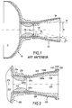
- FIG. 1 illustrates very schematically a rocket engine equipped with a diverging nozzle mobile.
- the rocket engine comprises an envelope 10 surrounding a combustion chamber 11 which opens into a nozzle.
- the nozzle 20 is formed of a neck 12 receiving the hot gases produced in the chamber of combustion and a divergent 20.
- the diverging 20 is mounted so mobile on the neck 12 which is secured to the bottom of the envelope 10.
- the divergent is the only moving part of the nozzle that allows by its pivoting to deflect the jet of combustion gases from the neck so to orient the trajectory of the thruster by changing the direction of the vector thrust.
- the diameter D of jet 32 of the nozzle narrows resulting in the detachment of the jet from the divergent wall as illustrated in FIG.
- nozzles are generally optimized for depending on the overall performance of the launcher.
- we define a expansion profile i.e. section variation in the nozzle depending from a certain altitude, called “adaptation" altitude, above which is the majority of the flight. Below this altitude, the nozzle is over-relaxed and the high external pressure can cause the detachment of the jet of the divergent wall.
- the detachment of the jet inside the nozzle can induce instabilities creating harmful vibratory stresses mechanically.
- the problem of reducing the pilotability due to the detachment of jet in the diverging is particularly noticeable in the nozzles at divergent mobile because it is the forces applied to the inner wall of the divergent that can direct the craft during his flight.
- the other directional nozzle systems such as thrust nozzles flexible, it is the whole vein of the nozzle that moves.
- the jet of gas ejected from the combustion chamber is deflected directly to the outlet of the col since the axis of the latter is displaced with that of the divergent.
- the orientation of the pushed vector is therefore at the level of the cervix of nozzle, that is to say upstream of the divergent, the detachment of the jet in the divergent then having practically no influence on the controllability of the nozzle.
- the present invention aims to provide a solution to the problem posed by jet separation in a divergent nozzle mobile in order to remove or reduce its influence on the flyability of the nozzle.
- this goal is achieved through an adaptation structure that is disposed within the diverging portion of the nozzle so as to reduce the divergent character of the vein of it and to increase the area application of the pressure forces exerted by the jet on the divergent when turning it.
- This structure makes it possible to fill the space between the inner wall of the divergent and the jet during its detachment to maintain contact, via said structure, between the jet and the divergent.
- it is possible to establish an asymmetrical pressure field in the divergent when turning it.
- the capabilities of thrust deviation of a movable divergent nozzle are not affected by an increase in external pressure.
- the shape, dimensions and layout of the structure adaptation are preferably chosen so as to optimize the efficiency in steering as well as the impact on the propulsive performance of the engine.
- the structure may for example be of axisymmetrical shape of revolution or have fin-shaped protuberances arranged uniformly on the structure in the vicinity of the section of exit of the diverging gases. Thus, even in the presence of a detachment of jet this one can be "hooked" by fins.
- the structure may be present for the duration of the flight or disappear at a given moment to find the normal configuration divergent. In the latter case, the structure is fixed to the divergent by connecting means with associated means, for example pyrotechnics, to control the breakdown of the means of link a determined time after firing.
- the structure can be made of a metal, a resin reinforced with elastomer fibers or a thermostructural composite material.
- the structure can also be erased gradually so to optimize the relaxation in the divergent according to a decrease, also progressive, external pressure.
- the problem of the influence of jet detachment on thrust deflection capabilities in a movable divergent nozzle can be solved by setting up of an annular piece at the end of the divergent at the section of gas outlet, the part having portions projecting inwards from the diverging so as to form, during the turning of the divergent, a surface for the application of the pressure forces exerted by the jet.
- the latter can be "hooked" by parts of the annular piece which is in solidarity with the divergent. This allows the jet to exert more force important on the steering divergence and, therefore, compensate for the decrease in the pressure forces applied to the wall of the diverge in case of jet separation.
- the shape, number and dimensions of the projecting parts of the annular part are preferably defined according to the level of the compensation force that one wishes to obtain during the detachment of the jet of the inner wall of the divergent.
- the annular piece can be attached to the divergent by connecting means permanent or by fastening systems whose break may be ordered at a given moment.
- the piece can be made in one material having an ephemeral behavior to the combustion gases so as to gradually disappear in contact with them.
- the invention also relates to a movable divergent nozzle equipped with one of the adaptation devices described above.
- Figure 2 illustrates very schematically the rear part of a rocket engine comprising an envelope 210 surrounding a chamber of combustion 211 in which is housed a block of solid propellant (no represent).
- the chamber 211 opens through its rear bottom 213 to the front of a nozzle comprising a neck 212 and a divergent 220.
- the collar 212 which not only defines the nozzle neck neatly said but also converge and a primer of divergent, is fixed by example by screwing into a ring 214 fixed to the bottom 213 of the envelope, so as to be secured to the bottom 213.
- the nozzle divergent 220 is movably mounted on the neck 212 nozzle which is integral with the casing 210.
- the movable divergent typically comprises an envelope 221 which may be for example metal having an inner layer 223 of insulating material such as a ablative composite for example composed of carbon or silica reinforcement and a phenolic resin matrix.
- the divergent mobile 220 comprises a piece 224 in the form of an inner ring made typically thermostructural composite material.
- Col 212 and the moving divergent 220 are in mutual contact by spherical surfaces respective 212a, 224a centered on the axis 215 of the nozzle.
- the divergent 220 is then movable on the neck 212 in several directions. So in steering the divergent, the thrust is oriented according to the angle formed between the axis 225 of the divergent and the axis 215 of the nozzle.
- the mobile nozzle divergent is connected to the fixed part thereof by via a mechanical link (not shown) comprising actuating means (eg cylinders) which make it possible to control the steering of the divergent.
- actuating means eg cylinders
- This type of assembly forming a nozzle to divergent mobile is well known per se and will not be described in more detail.
- An exemplary embodiment of such a nozzle is described in particular in the French patent application FR 02 08370.
- the movable diverging nozzle is advantageous in that that it can amplify the thrust deviation depending on the angle effective pivoting of the main axis of the divergent.
- this thrust deflection ability decreases significantly in the presence of a jet detachment. Indeed, when there is a space between the jet and the inner wall of the divergent illustrated in Figure 1, the impact of the jet on the divergent is very limited in because of its small contact surface with the divergent. More precisely, in the presence of a jet detachment in the divergent, the influence of divergent steering on the orientation of the thrust vector remains limited as long as the deflection remains within an angular range that does not allows the jet to substantially re-glue the inner wall of the diverging.
- a structure 230 is introduced into the divergent 220 of the nozzle.
- This structure 230 reduces the vein of the divergent to prevent the detachment of the jet when the external pressure is such that it would lead normally to jet detachment in the absence of such a structure.
- the shape and dimensions of the structure 230 can be very varied depending on the profile of the vein that one wishes to obtain in particular for optimize steering efficiency.
- the structure 230 presents preferably an external form 230b close to that of the moving part of the divergent where it should be arranged and an internal form 230a which maintains a substantially divergent structure to ensure good expansion of the combustion gases.
- the thickness of the structure 230 will be determined so as to fill the space between the jet and the inner wall divergent when detaching the jet. This thickness is preferably determined to fill the maximum space that can exist between the jet and the divergent during the detachment. The maximum detachment appears at the highest external pressure encountered during the flight. As example, for a missile intended to be launched in immersion, the thickness of structure 230 will be calculated to fill the space present at the depth of fire that corresponds to the highest external pressure during the flight phase.
- the structure 230 may be attached to the divergent by means of fastening 232 such as bolt members for example.
- structure 230 comprises a flange 231 which cooperates with a flange 2231 of the internal protection 223 of the divergent.
- the flange 231 may be attached to a flange of the envelope 221 of the diverge.
- the structure 230 may be present throughout the duration of the flight or else disappear at a specific moment from which the capabilities in natural turning of the divergent mobile are compatible with the needs in control of the machine in particular in order to optimize the performances propulsive engine. If the adaptation device is kept during the entire duration of the flight, the structure 230 and the internal protection 23 can constitute only one element.
- the fasteners 232 may be equipped with a system pyrotechnic explosive bolts or a cutting line end of the diverging or any other mechanical system for order the expulsion of the structure at a given moment.
- the structure 230 may consist of a material ablatable allowing a progressive disappearance of the structure. In the case of a missile launched in immersion for example, it allows to have a vein profile that expands as external pressure increases decreases, thus optimizing the expansion of the gases and, consequently, the propulsive performance during the flight.
- the progressive modification of the vein during the mission can also be obtained with a structure composed of several subassemblies nested in each other and releasable successively to determined moments of the mission.
- each subset may be attached to the neighboring or diverging subset by link whose break can be ordered.
- FIGS. 3A and 3B is distinguished particular of that of FIG. 2 in that the internal structure disposed inside the divergent has a non-axisymmetric shape in its downstream part.
- the structure 330 includes in its downstream part of the protuberances 333 protruding into the vein of the nozzle in the vicinity of the divergent outlet.
- protuberances 333 are profiled in the form of fins and distributed evenly around the axis of the structure 330.
- the protuberances 333 thus form obstacles for the jet inside the divergent. it allows the jet to always be in contact with a solidarity element of diverge and, therefore, allow for thrust deviation effective even in the presence of a jet detachment.
- the structure 330 is held inside the diverging part by fixing members 332 of type bolts inserted in holes drilled on the flange 331 of the structure, on the one hand, and on a flange 3211 of the outer envelope 321 of the divergent on the other hand.
- the structure 330 is here fixed by through a flange 3211, on the outer casing 321 of the diverge rather than its internal protection as shown in Figure 2.
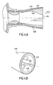
- FIGS. 4A and 4B illustrate another embodiment variant of FIG. structure allowing to hang the jet in the divergent according to the invention.
- the structure 430 has three protuberances 433 distributed evenly in the downstream part of the structure 430.
- structure 430 differs of that shown in FIGS. 3A and 3B in that it is fixed by bonding by means of a layer of adhesive 434 deposited on the protection internal 430 divergent 420.
- the structure of the set is Simplified since it does not form a fastening flange on the structure spray hook and on the envelope of the diverging or its protection internal.
- the bonded bond can be reinforced if necessary by pieces (not shown) perpendicular to the axis of the nozzle and penetrating into the structure without opening into the flow vein.
- the Structure 430 is advantageously made of ablatable material.
- the pilotability problem of the nozzle in case of jet detachment can be also solved with devices that are arranged not inside the divergent but at the exit of it.
- divergent 520 can be adapted with an annular piece 530 which is attached to the end of the divergent 520 at the exit section of the gases.
- the annular part 530 comprises projections 533 which extend inwardly of the divergent.
- the projections are used as additional areas of application for pressure exerted by the jet of ejected combustion gases. Indeed, when diverge in one direction, the jet will hit one or more of these projections on a more or less important surface according to the angle of steering applied.
- the geometry of the annular piece (shape, number and arrangement of projections, ...) can be very varied. It is mainly defined in according to the needs in terms of thrust deviation.
- the annular piece may be present during the entire phase of flight or disappear at a given moment.
- the room can therefore be attached to the diverging part by means of possibly equipped connecting means to control the expulsion of the structure at a time determined.
- the annular piece may consist of a ablatable material allowing a gradual disappearance of the structure during flight.
- the choice of the constituent material is varied. It depends in particular the gases and temperatures encountered and the method of elimination selected. It can be metallic, composite organic matrix consisting of fibers of glass, aramid, polyethylene or other and of resin such epoxy, phenolic or even elastomeric or thermostructural composite material such as carbon / carbon (C / C) or carbon / silicon carbide (C / SiC).
- a material that sublimates under the effect of hot gases such as a composite material of the fiberglass-reinforced resin type or a easily sublimable metal, such as aluminum.
Landscapes
- Engineering & Computer Science (AREA)
- Chemical & Material Sciences (AREA)
- Combustion & Propulsion (AREA)
- Mechanical Engineering (AREA)
- General Engineering & Computer Science (AREA)
- Toys (AREA)
- Aerodynamic Tests, Hydrodynamic Tests, Wind Tunnels, And Water Tanks (AREA)
- Testing Of Engines (AREA)
- Aiming, Guidance, Guns With A Light Source, Armor, Camouflage, And Targets (AREA)
- Jet Pumps And Other Pumps (AREA)
Abstract
Description
- la figure 1 est une vue très schématique, en coupe axiale, d'une tuyère à divergent mobile illustrant le phénomène de décollement de jet dans le divergent,
- la figure 2 est une vue très schématique, en coupe axiale, d'une tuyère équipée d'un dispositif d'adaptation conformément à un premier mode de réalisation de l'invention,
- les figures 3A, 3B, 4A et 4B sont des vues très schématiques illustrant deux variantes de réalisation du dispositif de la figure 2, et
- les figures 5A et 5B sont des vues très schématiques d'une tuyère équipée d'un dispositif d'adaptation conformément à un deuxième mode de réalisation de l'invention.
Claims (12)
- Dispositif d'adaptation pour le pilotage d'une tuyère de moteur fusée dans des conditions de pression externe telles qu'elles peuvent conduire à un décollement de jet dans la tuyère, la tuyère étant équipée d'un divergent (220) monté de façon mobile autour d'une partie fixe (212) de celle-ci, la déviation de poussée étant alors réalisée par le braquage du divergent (220) de manière à dévier le jet des gaz de combustion au contact de la paroi interne du divergent, caractérisé en ce qu'une structure (230) est disposée à l'intérieur du divergent (220) de façon à réduire le caractère divergent de la veine de celui-ci et à augmenter la zone d'application des efforts de pression exercés par le jet sur le divergent lors du braquage de celui-ci.
- Dispositif selon la revendication 1, caractérisé en ce que la structure (230) présente une forme axisymétrique de révolution.
- Dispositif selon la revendication 1, caractérisé en ce que la structure (330) comprend en outre des protubérances (333) en forme d'ailettes disposées uniformément sur la structure au voisinage de la section de sortie des gaz du divergent (320).
- Dispositif selon l'une des revendications 1 à 3, caractérisé en ce que la structure (230) est fixée au divergent par des moyens de liaison (232) et en ce que des moyens sont prévus pour commander la rupture par un système mécanique ou pyrotechnique desdits moyens de liaison à un instant déterminé.
- Dispositif selon l'une des revendications 1 à 3, caractérisé en ce que la structure est formée d'une pluralité d'éléments emboítés les uns dans les autres et en ce que chaque élément est fixé par des moyens de liaison dont la rupture peut être commandée à un instant déterminé.
- Dispositif selon l'une des revendications 1 à 5, caractérisé en ce que la structure (230) est constituée d'un métal, d'une résine armée de fibres d'élastomère ou d'un matériau composite thermostructural.
- Dispositif selon l'une des revendications 1 à 3, caractérisé en ce que la structure (230) est réalisée en un matériau ayant une tenue éphémère aux gaz de combustion de manière à disparaítre progressivement au contact de ces derniers.
- Dispositif d'adaptation pour le pilotage d'une tuyère de moteur fusée dans des conditions de pression externe telles qu'elles peuvent conduire à un décollement de jet dans la tuyère, la tuyère étant équipée d'un divergent (520) monté de façon mobile autour d'une partie fixe de celle-ci, la déviation de poussée étant alors réalisée par le braquage du divergent (520) de manière à dévier le jet des gaz de combustion au contact de la paroi interne du divergent, caractérisé en ce qu'une pièce annulaire (530) est fixée à l'extrémité du divergent au niveau de la section de sortie des gaz, ladite pièce annulaire (530) comportant des parties en saillie (533) vers l'intérieur du divergent de façon à former, lors du braquage du divergent, une surface supplémentaire solidaire du divergent pour l'application des efforts de pression exercés par le jet.
- Dispositif selon la revendication 8, caractérisé en ce que la pièce annulaire (530) est fixée au divergent par des moyens de liaison et en ce que des moyens sont prévus pour commander la rupture desdits moyens de liaison à un instant déterminé par un système mécanique ou pyrotechnique.
- Dispositif selon la revendication 8 ou 9, caractérisé en ce que la pièce annulaire (530) est constituée d'un métal, d'une résine armée de fibres d'élastomère ou d'un matériau composite thermostructural.
- Dispositif selon la revendication 8, caractérisé en ce que la pièce annulaire (530) est réalisée en un matériau ayant une tenue éphémère aux gaz de combustion de manière à disparaítre progressivement au contact de ces derniers.
- Tuyère à divergent mobile pour moteur fusée caractérisée en ce qu'elle est équipée d'un dispositif d'adaptation (230 ; 330 ; 430 ; 530) selon l'une des revendications 1 à 11.
Applications Claiming Priority (2)
| Application Number | Priority Date | Filing Date | Title |
|---|---|---|---|
| FR0314454 | 2003-12-10 | ||
| FR0314454A FR2863666B1 (fr) | 2003-12-10 | 2003-12-10 | Dispositif d'adaptation pour tuyere de moteur fusee a divergent mobile |
Publications (2)
| Publication Number | Publication Date |
|---|---|
| EP1541850A1 true EP1541850A1 (fr) | 2005-06-15 |
| EP1541850B1 EP1541850B1 (fr) | 2010-09-08 |
Family
ID=34508629
Family Applications (1)
| Application Number | Title | Priority Date | Filing Date |
|---|---|---|---|
| EP04292880A Expired - Lifetime EP1541850B1 (fr) | 2003-12-10 | 2004-12-06 | Dispositif d'adaptation pour tuyère de moteur fusée à divergent mobile |
Country Status (5)
| Country | Link |
|---|---|
| US (1) | US7406821B2 (fr) |
| EP (1) | EP1541850B1 (fr) |
| DE (1) | DE602004029001D1 (fr) |
| FR (1) | FR2863666B1 (fr) |
| NO (1) | NO338497B1 (fr) |
Cited By (1)
| Publication number | Priority date | Publication date | Assignee | Title |
|---|---|---|---|---|
| WO2017153677A1 (fr) * | 2016-03-07 | 2017-09-14 | Airbus Safran Launchers Sas | Moteur-fusée allume par le sol |
Families Citing this family (10)
| Publication number | Priority date | Publication date | Assignee | Title |
|---|---|---|---|---|
| US8020367B2 (en) * | 2007-03-16 | 2011-09-20 | General Electric Company | Nozzle with yaw vectoring vane |
| US20080264372A1 (en) * | 2007-03-19 | 2008-10-30 | Sisk David B | Two-stage ignition system |
| FR2920035B1 (fr) * | 2007-08-17 | 2013-09-06 | Airbus France | Turbomoteur a emission de bruit reduite pour aeronef |
| US8459036B2 (en) * | 2008-12-26 | 2013-06-11 | Rolls-Royce Corporation | Aircraft nozzle having actuators capable of changing a flow area of the aircraft nozzle |
| JP6361404B2 (ja) * | 2014-09-17 | 2018-07-25 | 三菱重工業株式会社 | 推力偏向装置、および、推力偏向装置を備える飛しょう体 |
| US10222189B2 (en) * | 2016-07-22 | 2019-03-05 | Raytheon Company | Stage separation mechanism and method |
| CN108150305B (zh) * | 2018-02-05 | 2023-05-12 | 西安航空学院 | 一种自适应脉冲爆震发动机收缩喷管 |
| US11585296B1 (en) * | 2020-01-14 | 2023-02-21 | Herbert U. Fluhler | Self compensating rocket engine enhancement |
| DE102024110781A1 (de) * | 2024-04-17 | 2025-10-23 | Arianegroup Gmbh | Startplattform und Raketentriebwerksdüse mit in die Verbrennungsgase ragender Zahngruppe |
| WO2025226271A1 (fr) * | 2024-04-25 | 2025-10-30 | Ursa Major Technologies, Inc. | Fabrication additive de moteur-fusée |
Citations (6)
| Publication number | Priority date | Publication date | Assignee | Title |
|---|---|---|---|---|
| US3079752A (en) | 1961-02-23 | 1963-03-05 | Thompson Ramo Wooldridge Inc | Variable expansion ratio nozzle |
| US3184917A (en) * | 1961-05-15 | 1965-05-25 | United Aircraft Corp | Reenforced seal for rocket nozzle |
| US3352495A (en) * | 1965-01-29 | 1967-11-14 | Thiokol Chemical Corp | Nozzle construction |
| US3392918A (en) * | 1962-07-09 | 1968-07-16 | Thiokol Chemical Corp | Rocket motor thrust control system |
| FR2724979A1 (fr) * | 1994-09-26 | 1996-03-29 | Europ Propulsion | Dispositif de protection contre l'effet bouchon d'eau lors de la mise a feu d'un missile lance en immersion |
| US5779151A (en) * | 1996-05-28 | 1998-07-14 | Regents Of The University Of California | Stepped nozzle |
Family Cites Families (14)
| Publication number | Priority date | Publication date | Assignee | Title |
|---|---|---|---|---|
| US2486019A (en) * | 1943-01-11 | 1949-10-25 | Daniel And Florence Guggenheim | Jet control apparatus applicable to entrainment of fluids |
| US2405415A (en) * | 1944-04-25 | 1946-08-06 | Carolus L Eksergian | Rocket projectile |
| US2912820A (en) * | 1953-07-31 | 1959-11-17 | Quentin R Whitmore | Combined ram jet and rocket engine |
| US3253403A (en) * | 1962-05-24 | 1966-05-31 | Kelsey Hayes Co | Nozzle having ablative coating |
| US3237402A (en) * | 1963-11-14 | 1966-03-01 | Steverding Bernard | Variable thrust nozzle |
| US3659423A (en) * | 1964-09-17 | 1972-05-02 | Goodyear Aerospace Corp | Moveable rocket |
| US3855789A (en) * | 1968-04-05 | 1974-12-24 | Us Navy | Explosive coupling assembly |
| US3737102A (en) * | 1970-09-21 | 1973-06-05 | Avco Corp | Corrosion resistant rocket nozzle |
| US4307839A (en) * | 1978-12-11 | 1981-12-29 | General Dynamics Corporation | Variable exit area ramjet nozzle |
| US4272956A (en) * | 1979-01-22 | 1981-06-16 | Thiokol Corporation | Time delay device for deployable rocket nozzle skirts |
| FR2503794B1 (fr) * | 1981-04-13 | 1986-04-25 | Europ Propulsion | Chambre de combustion de propulseur-fusee a divergent multiple |
| FR2705739B1 (fr) * | 1993-05-28 | 1995-08-18 | Europ Propulsion | Tuyère de moteur-fusée à section de sortie sélectivement réduite. |
| RU2037066C1 (ru) * | 1993-10-01 | 1995-06-09 | Владимир Павлович Знаменский | Способ получения тяги и устройство для его осуществления |
| US5511745A (en) * | 1994-12-30 | 1996-04-30 | Thiokol Corporation | Vectorable nozzle having jet vanes |
-
2003
- 2003-12-10 FR FR0314454A patent/FR2863666B1/fr not_active Expired - Fee Related
-
2004
- 2004-12-02 US US11/001,926 patent/US7406821B2/en not_active Expired - Lifetime
- 2004-12-06 DE DE602004029001T patent/DE602004029001D1/de not_active Expired - Lifetime
- 2004-12-06 EP EP04292880A patent/EP1541850B1/fr not_active Expired - Lifetime
- 2004-12-07 NO NO20045352A patent/NO338497B1/no not_active IP Right Cessation
Patent Citations (6)
| Publication number | Priority date | Publication date | Assignee | Title |
|---|---|---|---|---|
| US3079752A (en) | 1961-02-23 | 1963-03-05 | Thompson Ramo Wooldridge Inc | Variable expansion ratio nozzle |
| US3184917A (en) * | 1961-05-15 | 1965-05-25 | United Aircraft Corp | Reenforced seal for rocket nozzle |
| US3392918A (en) * | 1962-07-09 | 1968-07-16 | Thiokol Chemical Corp | Rocket motor thrust control system |
| US3352495A (en) * | 1965-01-29 | 1967-11-14 | Thiokol Chemical Corp | Nozzle construction |
| FR2724979A1 (fr) * | 1994-09-26 | 1996-03-29 | Europ Propulsion | Dispositif de protection contre l'effet bouchon d'eau lors de la mise a feu d'un missile lance en immersion |
| US5779151A (en) * | 1996-05-28 | 1998-07-14 | Regents Of The University Of California | Stepped nozzle |
Cited By (1)
| Publication number | Priority date | Publication date | Assignee | Title |
|---|---|---|---|---|
| WO2017153677A1 (fr) * | 2016-03-07 | 2017-09-14 | Airbus Safran Launchers Sas | Moteur-fusée allume par le sol |
Also Published As
| Publication number | Publication date |
|---|---|
| NO20045352L (no) | 2005-06-13 |
| EP1541850B1 (fr) | 2010-09-08 |
| US7406821B2 (en) | 2008-08-05 |
| NO338497B1 (no) | 2016-08-22 |
| DE602004029001D1 (de) | 2010-10-21 |
| US20050229587A1 (en) | 2005-10-20 |
| FR2863666A1 (fr) | 2005-06-17 |
| FR2863666B1 (fr) | 2006-03-24 |
Similar Documents
| Publication | Publication Date | Title |
|---|---|---|
| EP0737297B1 (fr) | Systeme de lancement et d'orientation d'engins volants | |
| EP1541850B1 (fr) | Dispositif d'adaptation pour tuyère de moteur fusée à divergent mobile | |
| EP1529163B1 (fr) | Moteur fusée à tuyère orientable | |
| EP0335761B1 (fr) | Engin aérien pourvu d'au moins un propulseur largable | |
| EP2956655B1 (fr) | Tuyère a divergent mobile avec système de protection thermique | |
| WO1998028533A1 (fr) | Divergent deployable pour propulseur | |
| EP2138698B1 (fr) | Dispositif pour amortir les efforts latéraux de décollement de jet agissant sur une tuyère de moteur-fusée | |
| FR2902184A1 (fr) | Appareil de lancement et de guidage de missile | |
| EP0836001B1 (fr) | Tuyère de moteur-fusée à inserts éjectables | |
| EP0626513B1 (fr) | Tuyère de moteur-fusée à section de sortie sélectivement réduite | |
| EP0626512B1 (fr) | Tuyère de moteur-fusée à divergent échancré | |
| FR2731471A1 (fr) | Moteur-fusee a propergol solide avec charges propulsives a combustion exterieure et a combustion interieure | |
| EP1101030B1 (fr) | Tuyere compacte et modulable pour le pilotage d'engins aerospatiaux | |
| EP3617075A1 (fr) | Dispositif de liaison localisee a separation commandee comprenant une couche de liaison multidirectionnelle | |
| EP0632197B1 (fr) | Tuyère de moteur-fusée à diffuseur éjectable | |
| FR2995941A1 (fr) | Divergent a deviateurs de jet pour propulseurs a charge solide | |
| WO2017013341A1 (fr) | Dispositif de modulation de section d'éjection de gaz | |
| EP0508851B1 (fr) | Amortisseur d'onde de choc pour un système de propulsion à réaction | |
| EP1209344A1 (fr) | Tuyères de fusée | |
| FR2567197A1 (fr) | Propulseur a poudre pour projectile tire dans un tube de lancement | |
| EP2209981B1 (fr) | Tuyère propulsive de détente d'un jet supersonique de gaz avec un flux secondaire d'écran | |
| FR2657158A1 (fr) | Munition perforante pour cible a haute resistance mecanique. | |
| CA2179929A1 (fr) | Systeme de lancement et d'orientation d'engins volants | |
| FR2656083A1 (fr) | Perfectionnements apportes aux projectiles agissant en survol ou au devant de la cible. | |
| FR3074480A1 (fr) | Separation en deux temps de viroles appartenant a un lanceur |
Legal Events
| Date | Code | Title | Description |
|---|---|---|---|
| PUAI | Public reference made under article 153(3) epc to a published international application that has entered the european phase |
Free format text: ORIGINAL CODE: 0009012 |
|
| 17P | Request for examination filed |
Effective date: 20041210 |
|
| AK | Designated contracting states |
Kind code of ref document: A1 Designated state(s): AT BE BG CH CY CZ DE DK EE ES FI FR GB GR HU IE IS IT LI LT LU MC NL PL PT RO SE SI SK TR |
|
| AX | Request for extension of the european patent |
Extension state: AL BA HR LV MK YU |
|
| AKX | Designation fees paid |
Designated state(s): DE FR GB IT |
|
| 17Q | First examination report despatched |
Effective date: 20080513 |
|
| GRAP | Despatch of communication of intention to grant a patent |
Free format text: ORIGINAL CODE: EPIDOSNIGR1 |
|
| GRAS | Grant fee paid |
Free format text: ORIGINAL CODE: EPIDOSNIGR3 |
|
| GRAA | (expected) grant |
Free format text: ORIGINAL CODE: 0009210 |
|
| AK | Designated contracting states |
Kind code of ref document: B1 Designated state(s): DE FR GB IT |
|
| REG | Reference to a national code |
Ref country code: GB Ref legal event code: FG4D Free format text: NOT ENGLISH |
|
| REF | Corresponds to: |
Ref document number: 602004029001 Country of ref document: DE Date of ref document: 20101021 Kind code of ref document: P |
|
| PLBE | No opposition filed within time limit |
Free format text: ORIGINAL CODE: 0009261 |
|
| STAA | Information on the status of an ep patent application or granted ep patent |
Free format text: STATUS: NO OPPOSITION FILED WITHIN TIME LIMIT |
|
| 26N | No opposition filed |
Effective date: 20110609 |
|
| REG | Reference to a national code |
Ref country code: DE Ref legal event code: R097 Ref document number: 602004029001 Country of ref document: DE Effective date: 20110609 |
|
| REG | Reference to a national code |
Ref country code: DE Ref legal event code: R082 Ref document number: 602004029001 Country of ref document: DE Representative=s name: CBDL PATENTANWAELTE, DE |
|
| REG | Reference to a national code |
Ref country code: DE Ref legal event code: R081 Ref document number: 602004029001 Country of ref document: DE Owner name: HERAKLES, FR Free format text: FORMER OWNER: SNECMA PROPULSION SOLIDE, LE HAILLAN, FR Effective date: 20130114 Ref country code: DE Ref legal event code: R082 Ref document number: 602004029001 Country of ref document: DE Representative=s name: CBDL PATENTANWAELTE, DE Effective date: 20130114 |
|
| REG | Reference to a national code |
Ref country code: GB Ref legal event code: 732E Free format text: REGISTERED BETWEEN 20130221 AND 20130227 |
|
| REG | Reference to a national code |
Ref country code: FR Ref legal event code: TP Owner name: HERAKLES, FR Effective date: 20130513 |
|
| REG | Reference to a national code |
Ref country code: FR Ref legal event code: PLFP Year of fee payment: 12 |
|
| REG | Reference to a national code |
Ref country code: FR Ref legal event code: PLFP Year of fee payment: 13 |
|
| REG | Reference to a national code |
Ref country code: FR Ref legal event code: PLFP Year of fee payment: 14 |
|
| REG | Reference to a national code |
Ref country code: GB Ref legal event code: 732E Free format text: REGISTERED BETWEEN 20180215 AND 20180221 |
|
| REG | Reference to a national code |
Ref country code: FR Ref legal event code: CD Owner name: ARIANEGROUP SAS, FR Effective date: 20180621 Ref country code: FR Ref legal event code: TP Owner name: ARIANEGROUP SAS, FR Effective date: 20180621 |
|
| PGFP | Annual fee paid to national office [announced via postgrant information from national office to epo] |
Ref country code: DE Payment date: 20181211 Year of fee payment: 15 |
|
| PGFP | Annual fee paid to national office [announced via postgrant information from national office to epo] |
Ref country code: HR Payment date: 20181204 Year of fee payment: 6 Ref country code: GB Payment date: 20181218 Year of fee payment: 15 |
|
| REG | Reference to a national code |
Ref country code: DE Ref legal event code: R082 Ref document number: 602004029001 Country of ref document: DE Representative=s name: CBDL PATENTANWAELTE, DE Ref country code: DE Ref legal event code: R081 Ref document number: 602004029001 Country of ref document: DE Owner name: ARIANEGROUP SAS, FR Free format text: FORMER OWNER: HERAKLES, LE HAILLAN, FR |
|
| REG | Reference to a national code |
Ref country code: DE Ref legal event code: R082 Ref document number: 602004029001 Country of ref document: DE Representative=s name: CBDL PATENTANWAELTE, DE Ref country code: DE Ref legal event code: R081 Ref document number: 602004029001 Country of ref document: DE Owner name: ARIANEGROUP SAS, FR Free format text: FORMER OWNER: AIRBUS SAFRAN LAUNCHERS SAS, ISSY-LES-MOULINEAUX, FR |
|
| REG | Reference to a national code |
Ref country code: DE Ref legal event code: R119 Ref document number: 602004029001 Country of ref document: DE |
|
| GBPC | Gb: european patent ceased through non-payment of renewal fee |
Effective date: 20191206 |
|
| PG25 | Lapsed in a contracting state [announced via postgrant information from national office to epo] |
Ref country code: IT Free format text: LAPSE BECAUSE OF NON-PAYMENT OF DUE FEES Effective date: 20191206 Ref country code: DE Free format text: LAPSE BECAUSE OF NON-PAYMENT OF DUE FEES Effective date: 20200701 Ref country code: GB Free format text: LAPSE BECAUSE OF NON-PAYMENT OF DUE FEES Effective date: 20191206 |
|
| PGFP | Annual fee paid to national office [announced via postgrant information from national office to epo] |
Ref country code: FR Payment date: 20231227 Year of fee payment: 20 |