EP1541955A2 - Radiateur avec refroidisseur d'huile - Google Patents
Radiateur avec refroidisseur d'huile Download PDFInfo
- Publication number
- EP1541955A2 EP1541955A2 EP04292910A EP04292910A EP1541955A2 EP 1541955 A2 EP1541955 A2 EP 1541955A2 EP 04292910 A EP04292910 A EP 04292910A EP 04292910 A EP04292910 A EP 04292910A EP 1541955 A2 EP1541955 A2 EP 1541955A2
- Authority
- EP
- European Patent Office
- Prior art keywords
- tank
- oil cooler
- side wall
- openings
- connecting pipes
- Prior art date
- Legal status (The legal status is an assumption and is not a legal conclusion. Google has not performed a legal analysis and makes no representation as to the accuracy of the status listed.)
- Granted
Links
- 230000000903 blocking effect Effects 0.000 claims abstract description 24
- 230000000717 retained effect Effects 0.000 claims abstract description 13
- 238000005219 brazing Methods 0.000 claims description 24
- 238000004873 anchoring Methods 0.000 claims description 15
- 238000000034 method Methods 0.000 claims description 14
- 238000004891 communication Methods 0.000 claims description 6
- 238000005452 bending Methods 0.000 claims description 2
- 238000010438 heat treatment Methods 0.000 description 5
- 229910052782 aluminium Inorganic materials 0.000 description 4
- XAGFODPZIPBFFR-UHFFFAOYSA-N aluminium Chemical compound [Al] XAGFODPZIPBFFR-UHFFFAOYSA-N 0.000 description 3
- 241000276425 Xiphophorus maculatus Species 0.000 description 2
- 238000005253 cladding Methods 0.000 description 2
- 239000000463 material Substances 0.000 description 2
- 230000008646 thermal stress Effects 0.000 description 2
- HCHKCACWOHOZIP-UHFFFAOYSA-N Zinc Chemical compound [Zn] HCHKCACWOHOZIP-UHFFFAOYSA-N 0.000 description 1
- 230000005540 biological transmission Effects 0.000 description 1
- 238000001816 cooling Methods 0.000 description 1
- 239000000498 cooling water Substances 0.000 description 1
- 230000007797 corrosion Effects 0.000 description 1
- 238000005260 corrosion Methods 0.000 description 1
- 230000000593 degrading effect Effects 0.000 description 1
- 238000009792 diffusion process Methods 0.000 description 1
- 230000000694 effects Effects 0.000 description 1
- 230000004048 modification Effects 0.000 description 1
- 238000012986 modification Methods 0.000 description 1
- 230000002787 reinforcement Effects 0.000 description 1
- 239000011701 zinc Substances 0.000 description 1
- 229910052725 zinc Inorganic materials 0.000 description 1
Images





Classifications
-
- F—MECHANICAL ENGINEERING; LIGHTING; HEATING; WEAPONS; BLASTING
- F28—HEAT EXCHANGE IN GENERAL
- F28D—HEAT-EXCHANGE APPARATUS, NOT PROVIDED FOR IN ANOTHER SUBCLASS, IN WHICH THE HEAT-EXCHANGE MEDIA DO NOT COME INTO DIRECT CONTACT
- F28D9/00—Heat-exchange apparatus having stationary plate-like or laminated conduit assemblies for both heat-exchange media, the media being in contact with different sides of a conduit wall
- F28D9/0031—Heat-exchange apparatus having stationary plate-like or laminated conduit assemblies for both heat-exchange media, the media being in contact with different sides of a conduit wall the conduits for one heat-exchange medium being formed by paired plates touching each other
- F28D9/0043—Heat-exchange apparatus having stationary plate-like or laminated conduit assemblies for both heat-exchange media, the media being in contact with different sides of a conduit wall the conduits for one heat-exchange medium being formed by paired plates touching each other the plates having openings therein for circulation of at least one heat-exchange medium from one conduit to another
-
- F—MECHANICAL ENGINEERING; LIGHTING; HEATING; WEAPONS; BLASTING
- F28—HEAT EXCHANGE IN GENERAL
- F28F—DETAILS OF HEAT-EXCHANGE AND HEAT-TRANSFER APPARATUS, OF GENERAL APPLICATION
- F28F9/00—Casings; Header boxes; Auxiliary supports for elements; Auxiliary members within casings
- F28F9/02—Header boxes; End plates
- F28F9/0234—Header boxes; End plates having a second heat exchanger disposed there within, e.g. oil cooler
-
- F—MECHANICAL ENGINEERING; LIGHTING; HEATING; WEAPONS; BLASTING
- F28—HEAT EXCHANGE IN GENERAL
- F28F—DETAILS OF HEAT-EXCHANGE AND HEAT-TRANSFER APPARATUS, OF GENERAL APPLICATION
- F28F2250/00—Arrangements for modifying the flow of the heat exchange media, e.g. flow guiding means; Particular flow patterns
- F28F2250/10—Particular pattern of flow of the heat exchange media
- F28F2250/104—Particular pattern of flow of the heat exchange media with parallel flow
-
- Y—GENERAL TAGGING OF NEW TECHNOLOGICAL DEVELOPMENTS; GENERAL TAGGING OF CROSS-SECTIONAL TECHNOLOGIES SPANNING OVER SEVERAL SECTIONS OF THE IPC; TECHNICAL SUBJECTS COVERED BY FORMER USPC CROSS-REFERENCE ART COLLECTIONS [XRACs] AND DIGESTS
- Y10—TECHNICAL SUBJECTS COVERED BY FORMER USPC
- Y10S—TECHNICAL SUBJECTS COVERED BY FORMER USPC CROSS-REFERENCE ART COLLECTIONS [XRACs] AND DIGESTS
- Y10S165/00—Heat exchange
- Y10S165/916—Oil cooler
-
- Y—GENERAL TAGGING OF NEW TECHNOLOGICAL DEVELOPMENTS; GENERAL TAGGING OF CROSS-SECTIONAL TECHNOLOGIES SPANNING OVER SEVERAL SECTIONS OF THE IPC; TECHNICAL SUBJECTS COVERED BY FORMER USPC CROSS-REFERENCE ART COLLECTIONS [XRACs] AND DIGESTS
- Y10—TECHNICAL SUBJECTS COVERED BY FORMER USPC
- Y10T—TECHNICAL SUBJECTS COVERED BY FORMER US CLASSIFICATION
- Y10T29/00—Metal working
- Y10T29/49—Method of mechanical manufacture
- Y10T29/4935—Heat exchanger or boiler making
- Y10T29/49366—Sheet joined to sheet
-
- Y—GENERAL TAGGING OF NEW TECHNOLOGICAL DEVELOPMENTS; GENERAL TAGGING OF CROSS-SECTIONAL TECHNOLOGIES SPANNING OVER SEVERAL SECTIONS OF THE IPC; TECHNICAL SUBJECTS COVERED BY FORMER USPC CROSS-REFERENCE ART COLLECTIONS [XRACs] AND DIGESTS
- Y10—TECHNICAL SUBJECTS COVERED BY FORMER USPC
- Y10T—TECHNICAL SUBJECTS COVERED BY FORMER US CLASSIFICATION
- Y10T29/00—Metal working
- Y10T29/49—Method of mechanical manufacture
- Y10T29/4935—Heat exchanger or boiler making
- Y10T29/49393—Heat exchanger or boiler making with metallurgical bonding
Definitions
- the present invention relates to an oil-cooler-equipped radiator in which an oil cooler is fixed in a radiator by brazing while the oil cooler is accommodated in a tank of the radiator for a motor vehicle, and/or others.
- an all-aluminum radiator in which the tank and core part of the radiator are made of aluminum has been developed in recent years.
- brazing of an oil cooler and a tank of the radiator is performed while the oil cooler made of aluminum is accommodated in the tank.
- the present invention has been made in view of the above-described problems, and it is an object of the present invention to provide an oil-cooler-equipped radiator in which an oil cooler can be heat-treated together with the radiator while the oil cooler is accommodated in a tank of the radiator so that each component of the oil cooler can be brazed at the same time, without performing a troublesome operation of removing jigs used for temporary assembling and without causing deformation of each member due to heat treatment or brazing failure.
- an oil-cooler-equipped radiator comprising: a tank provided in the radiator; and an oil cooler that is accommodated in the tank of the radiator and has a heat exchanger including a plurality of stacked element units communicating with each other, a pair of tube plates fixed while being in communication with the outermost element units of the heat exchanger, and a pair of connecting pipes disposed through openings in a side wall of the tank and through openings in both end portions in the longitudinal direction of one of the tube plates; wherein the connecting pipes are formed with a blocking flange that is wide enough to block the opening of the tank and disposed at a mid portion of each of the connecting pipes on its outer surface such that the blocking flange is in contact with the outer surface of the side wall of the tank; the width of each opening in the side wall of the tank is larger than at least the outer diameter of the connecting pipe in the longitudinal direction of the oil cooler; and before brazing the oil-cooler-equipped radiator which is brazed while the oil cooler is accommodated in the tank
- the oil-cooler-equipped radiator has the above-described configuration. That is, the oil cooler, which includes the heat exchanger including the plurality of stacked element units communicating with each other; and the pair of tube plates fixed such that the tube plates are in communication with the outermost element units of the heat exchanger, is held by the holding plates, each having bent portions so as to have a substantially U-shaped cross section. Since the top portions of both side pieces of each holding plate are disposed through the side wall of the tank and are bent at the outer surface of the tank, each circular interposed member and the oil cooler are retained by being sandwiched between the middle supporter pieces of the holding plates and the side wall of the tank in the stacking direction of the element units, while the oil cooler is movable in the longitudinal direction with respect to the side wall of the tank. Further, by inserting the connecting pipes of the oil cooler through the openings of the tank so as to temporarily assemble the connecting pipes to the openings of the tube plate, both blocking flanges are kept in contact with the outer surface of the side wall of the tank.
- the holding plates which are incorporated together with the oil cooler into the tank of the radiator, jigs for temporarily assembling the oil cooler and those for temporarily attaching the oil cooler to the radiator are not required. Therefore, an operation of removing the jigs need not be performed.
- the radiator can be assembled and transferred while the temporarily-assembled oil cooler is accommodated in the tank, and the oil cooler and the radiator can be brazed together.
- each opening in the side wall of the tank is wider than at least the outer diameter of each of the connecting pipes in the longitudinal direction of the oil cooler.
- each circular interposed member and the oil cooler are sandwiched between the middle supporter pieces of the holding plates and the side wall of the tank in the stacking direction of the element units, while the oil cooler is movable in the longitudinal direction with respect to the side wall of the tank.
- the connecting pipes can relatively move freely at least in the longitudinal direction of the oil cooler within the range of the large openings in the side wall of the tank, with respect to the side wall of the tank. Therefore, thermal stress can be absorbed even if heat is hard to be transferred evenly to the oil cooler in the tank during a brazing process, causing difference in thermal expansion due to the temperature difference between the side wall of the tank and the oil cooler inside the tank.
- a method of brazing of an oil-cooler-equipped radiator while an oil cooler is accommodated in a tank of the radiator the oil cooler being equipped with a heat exchanger including a plurality of stacked element units communicating with each other; a pair of tube plates fixed while being in communication with the outermost element units of the heat exchanger; and a pair of connecting pipes disposed through openings in a side wall of the tank and through openings in both end portions in the longitudinal direction of one of the tube plates
- the method comprising: forming the width of each opening in the side wall of the tank to be larger than at least the outer diameter of the connecting pipe in the longitudinal direction of the oil cooler; forming a blocking flange that is wide enough to block the opening of the tank and disposed at a mid portion of each of the connecting pipes on its outer surface such that the blocking flange is in contact with the outer surface of the side wall of the tank; inserting the connecting pipes into the openings of the tank so as to temporarily assemble the connecting pipes into the opening
- FIG. 1 shows the entire oil-cooler-equipped radiator according to the embodiment of the present invention
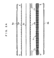
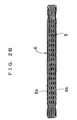
- FIGS. 2A and 2B are exploded views of the main parts of the oil cooler
- FIG. 3 is a plan view of a shell of the oil cooler
- FIG. 4 is a plan view of a tube plate of the oil cooler.
- FIG. 5 is a cross-sectional view taken along the line S5-S5 in FIG. 1;
- FIG. 6 is a cross-sectional view taken along the line S6-S6 in FIG. 1;
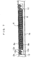
- FIG. 7 shows the oil cooler in a temporarily-assembled state; and
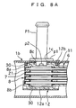
- FIGS. 8A and 8B illustrate a quick-fit method.
- the oil-cooler-equipped radiator of the embodiment includes a pair of seat plates 2a and 2b provided with tanks 1a and 1b, respectively; tubes 3 and corrugated fins 4 disposed between the seat plates 2a and 2b; and reinforcements 5a and 5b for connecting both end portions of the seat plates 2a and 2b so as to mechanically reinforce the seat plates 2a and 2b.
- An oil cooler 6 is accommodated in the tank 1b. All the components including the oil cooler 6 are made of aluminum. The oil cooler 6 will be described in detail later.
- the oil cooler 6 includes a heat exchanger 8, which includes a plurality of (in the embodiment, four layers of) element units 7 stacked one on another via sheets 21.
- Each element unit 7 includes a pair of shells 6a, the periphery thereof being raised so as to form a dish shape and both end portions thereof having an opening 30, and the pair of shells 6a are engaged with each other with a corrugated inner fin 6c therebetween.
- Each shell 6a is provided with blades for diffusing oil.
- Tube plates 8a and 8b are fixedly stacked on the outermost element units 7 on both sides in the stacking direction.
- the tube plates 8a and 8b are fixed to the outermost element units 7, respectively, by being caulked at caulking portions K.
- openings 8c are disposed at both end portions of the tube plate 8a.
- Connecting pipes P1 and P2 are inserted through the openings 8c so as to be connected.
- the tube plate 8a also has guide grooves 10 for allowing oil to flow in the longitudinal direction of the oil cooler 6.
- the connecting pipes P1 and P2 will be described in detail later.
- a waxed brazing sheet as cladding material, is used in at least one side thereof.
- the oil cooler 6 having the above-described configuration is placed at a predetermined position in the tank 1b, with a circular interposed member 11 disposed between the outer edge portion of each of the openings 8c of the tube plate 8a and the inner edge portion of each of openings 1c of the tank 1b, as shown in FIGS. 1, 5, and 6. Accordingly, the oil cooler 6 is assembled such that the connecting pipes P1 and P2 are protruded outward through the both openings 1c in the side wall of the tank 1b.
- the oil cooler 6 functions as a cooling circuit, in which oil for the engine or automatic transmission (AT) flows from the connecting pipe P1 through the element units 7 of the heat exchanger 8 in the longitudinal direction thereof, so that the heat exchange between the oil and cooling water in the tank 1b is carried out, and then the oil is discharged from the connecting pipe P2.
- AT automatic transmission
- a blocking flange p1 is integrally formed in each of the connecting pipes P1 and P2.
- the blocking flange p1 is positioned at a mid portion near the inserted side on the outer surface of the connecting pipe P1, while being in contact with the outer surface of the side wall of the tank 1b, and is wide enough to block the opening 1c.
- anchoring portions p2 are projected at two positions facing each other in the diameter direction of each connecting pipe from its outer surface, at the inserted-side end thereof.
- each opening 1c in the side wall of the tank 1b is larger than at least the outer diameter of each of the connecting pipes P1 and P2 in the longitudinal direction of the oil cooler 6.
- a waxed brazing sheet as cladding material, is used in at least one side thereof at each contact portion, as in the oil cooler 6.
- the oil cooler 6 is temporarily attached to the side wall of the tank 1b, having the opening 1c, by using a holding plate 12.
- the holding plate 12 is composed of a middle supporter piece 12a, which is in contact with the outer surface of the tube plate 8b so as to support it, and two side pieces 12b extending in parallel along both side faces of the oil cooler 6 from both ends of the middle supporter piece 12a, so that the holding plate 12 has a substantially U-shaped cross section.
- the oil cooler 6 is held by this holding plate 12.
- the top portions of both side pieces 12b of the holding plate 12 are disposed through the side wall of the tank 1b and are bent at the outer surface of the tank 1b, the oil cooler 6 is retained by being sandwiched between the middle supporter piece 12a of the holding plate 12 and the side wall of the tank 1b in the stacking direction of the element units 7. Accordingly, the oil cooler 6 is temporarily attached to the side wall of the tank 1b such that the oil cooler 6 is movable in the longitudinal direction with respect to the side wall of the tank 1b.
- the connecting pipe P1 is fixed by a quick-fit method. Specifically, the connecting pipe P1 is inserted through the opening 8c in the direction from the upper side toward the lower side of FIG. 8A such that both anchoring portions p2 are directed in the major-axis direction of the oval opening 8c of the tube plate 8a. Then, by rotating the connecting pipe P1 about the axis in the clockwise direction or in the counterclockwise direction in FIG. 8B, the anchoring portions p2 are engaged with the opening 8c of the tube plate 8a such that the blocking flange p1 of the connecting pipe P1 is in contact with the outer surface of the side wall of the tank 1b so as to block the opening 1c. Accordingly, the connecting pipe P1 is temporarily assembled into the tank 1b and the oil cooler 6.
- the temporarily-assembled oil-cooler-equipped radiator is transferred into a heat treating furnace, not shown, and is heat-treated, so that each contact part of the components is brazed and the components are integrated.
- the oil cooler 6, which includes the heat exchanger 8 including the plurality of stacked element units 7 communicating with each other; and the pair of tube plates 8a and 8b fixed such that the tube plates are in communication with the outermost element units 7 of the heat exchanger 8, is held by the holding plates 12, each having bent portions so as to have a substantially U-shaped cross section.
- each circular interposed member 11 and the oil cooler 6 are retained by being sandwiched between the middle supporter pieces 12a of the holding plates 12 and the side wall of the tank 1b in the stacking direction of the element units 7, while the oil cooler 6 is movable in the longitudinal direction with respect to the side wall of the tank 1b.
- both blocking flanges p1 are kept in contact with the outer surface of the side wall of the tank 1b.
- the holding plates 12, which are incorporated together with the oil cooler 6 into the tank 1b of the radiator jigs for temporarily assembling the oil cooler 6 and those for temporarily attaching the oil cooler 6 to the radiator are not required. Therefore, an operation of removing the jigs need not be performed.
- the radiator can be assembled and transferred while the temporarily-assembled oil cooler 6 is accommodated in the tank 1b, and the oil cooler 6 and the radiator can be brazed together.
- the blocking flange p1 which is in contact with the outer surface of the side wall of the tank 1b and is wide enough to block the opening 1c, is integrally-formed in each of the connecting pipes P1 and P2, at a mid portion near the inserted side of the pipe on its outer surface.
- the anchoring portions p2 are projected at two positions facing each other in the diameter direction of each connecting pipe from its outer surface, at the inserted-side end thereof.
- each opening 1c in the side wall of the tank 1 b is wider than at least the outer diameter of each of the connecting pipes P1 and P2 in the longitudinal direction of the oil cooler 6.
- each circular interposed member 11 and the oil cooler 6 are sandwiched between the middle supporter pieces 12a of the holding plates 12 and the side wall of the tank 1b in the stacking direction of the element units 7, while the oil cooler 6 is movable in the longitudinal direction with respect to the side wall of the tank 1b.
- the connecting pipes P1 and P2 can relatively move freely at least in the longitudinal direction of the oil cooler 6 within the range of the large openings 1c in the side wall of the tank 1b, with respect to the side wall of the tank 1b. Therefore, thermal stress can be absorbed even if heat is hard to be transferred evenly to the oil cooler 6 in the tank 1b during a brazing process, causing difference in thermal expansion due to the temperature difference between the side wall of the tank 1b and the oil cooler 6 inside the tank 1b.
- the connecting pipes P1 and P2 are temporarily assembled by engaging the anchoring portions p2 with the openings 8c.
- a wall portion may be provided in each opening of the tube plate 8a, and the connecting pipes P1 and P2 may be press-fitted thereto.
- the connecting pipes P1 and P2 may be screwed in the tube plate 8a.
- the blocking flange p1 is integrally-formed in each of the connecting pipes P1 and P2.
- the blocking flange may be separately formed, and an anchoring protrusion for anchoring the blocking flange p1 may be provided in each of the connecting pipes P1 and P2.
Landscapes
- Engineering & Computer Science (AREA)
- Physics & Mathematics (AREA)
- Thermal Sciences (AREA)
- Mechanical Engineering (AREA)
- General Engineering & Computer Science (AREA)
- Heat-Exchange Devices With Radiators And Conduit Assemblies (AREA)
Applications Claiming Priority (2)
| Application Number | Priority Date | Filing Date | Title |
|---|---|---|---|
| JP2003409279 | 2003-12-08 | ||
| JP2003409279A JP2005172270A (ja) | 2003-12-08 | 2003-12-08 | オイルクーラ内蔵ラジエータ |
Publications (3)
| Publication Number | Publication Date |
|---|---|
| EP1541955A2 true EP1541955A2 (fr) | 2005-06-15 |
| EP1541955A3 EP1541955A3 (fr) | 2006-01-18 |
| EP1541955B1 EP1541955B1 (fr) | 2007-12-12 |
Family
ID=34510476
Family Applications (1)
| Application Number | Title | Priority Date | Filing Date |
|---|---|---|---|
| EP04292910A Expired - Lifetime EP1541955B1 (fr) | 2003-12-08 | 2004-12-08 | Radiateur avec refroidisseur d'huile |
Country Status (4)
| Country | Link |
|---|---|
| US (1) | US6988541B2 (fr) |
| EP (1) | EP1541955B1 (fr) |
| JP (1) | JP2005172270A (fr) |
| DE (1) | DE602004010606T2 (fr) |
Cited By (2)
| Publication number | Priority date | Publication date | Assignee | Title |
|---|---|---|---|---|
| CN1884960B (zh) * | 2005-06-21 | 2011-12-21 | 康奈可关精株式会社 | 油冷却器 |
| CN111542725A (zh) * | 2017-08-17 | 2020-08-14 | 法雷奥自动系统公司 | 具有增强装置的热交换器 |
Families Citing this family (22)
| Publication number | Priority date | Publication date | Assignee | Title |
|---|---|---|---|---|
| US7147040B2 (en) * | 2004-01-08 | 2006-12-12 | Delphi Technologies, Inc. | Heat exchanger with tank utilizing integral positioning guides |
| DE102004007510B4 (de) * | 2004-02-13 | 2019-08-14 | Mahle International Gmbh | Wärmeübertrager, insbesondere Ölkühler für Kraftfahrzeuge |
| US7188664B2 (en) * | 2005-04-21 | 2007-03-13 | Delphi Technologies, Inc. | Aluminum radiator tank with oil cooler clinch fitting |
| EP1739380B1 (fr) * | 2005-06-21 | 2012-03-21 | Calsonic Kansei Corporation | Refroidisseur d'huile |
| US7554343B2 (en) * | 2005-07-25 | 2009-06-30 | Piezoinnovations | Ultrasonic transducer control method and system |
| JP2007278613A (ja) | 2006-04-07 | 2007-10-25 | Calsonic Kansei Corp | オイルクーラ内蔵ラジエータ |
| US20080078538A1 (en) * | 2006-09-28 | 2008-04-03 | Ali Jalilevand | Heat exchanger plate having integrated turbulation feature |
| US7992622B2 (en) * | 2007-05-15 | 2011-08-09 | Delphi Technologies, Inc. | Oil cooler fitting assembly |
| US20100059215A1 (en) * | 2008-09-11 | 2010-03-11 | Proliance International Inc. | Plate type oil cooler |
| CN102272548B (zh) * | 2009-01-09 | 2014-07-23 | 康奈可关精株式会社 | 复合型换热器 |
| ATE554361T1 (de) * | 2009-04-28 | 2012-05-15 | Abb Research Ltd | Wärmerohr mit gewundenem rohr |
| EP2246654B1 (fr) * | 2009-04-29 | 2013-12-11 | ABB Research Ltd. | Échangeur thermique à thermosiphon à rangs multiples |
| JP6047800B2 (ja) * | 2012-06-22 | 2016-12-21 | オリオン機械株式会社 | 熱交換装置 |
| FR3004527B1 (fr) * | 2013-04-16 | 2015-05-15 | Fives Cryo | Echangeur de chaleur avec ensemble de liaison de tete de distribution a double fonction |
| KR101439199B1 (ko) * | 2013-09-03 | 2014-09-12 | 정영수 | 동파방지수단이 구비된 난방기의 열교환장치 |
| FR3013816A1 (fr) * | 2013-11-26 | 2015-05-29 | Air Liquide | Element de support, circuit de fluide cryogenique et procede correspondants |
| JP2020085288A (ja) * | 2018-11-20 | 2020-06-04 | 株式会社デンソー | 熱交換器 |
| KR102765868B1 (ko) | 2019-07-29 | 2025-02-11 | 엘지전자 주식회사 | 판형 열교환기 |
| JP7363570B2 (ja) * | 2020-02-25 | 2023-10-18 | 株式会社富士通ゼネラル | 積層体 |
| CN111965335B (zh) * | 2020-08-19 | 2022-01-28 | 西南石油大学 | 一种成品油管道的拖尾油模拟实验装置 |
| JP7545835B2 (ja) * | 2020-09-07 | 2024-09-05 | リンナイ株式会社 | プレート式熱交換器 |
| DE102022212148A1 (de) * | 2022-11-15 | 2024-05-16 | Mahle International Gmbh | Crimp-Werkzeug und damit hergestellter Wärmeübertrager |
Family Cites Families (17)
| Publication number | Priority date | Publication date | Assignee | Title |
|---|---|---|---|---|
| US4227570A (en) * | 1979-10-01 | 1980-10-14 | Caterpillar Tractor Co. | Heat exchange structure |
| SE462059B (sv) * | 1986-12-19 | 1990-04-30 | Blackstone Sweden | Vaermevaexlare med platta roer, vilka roer bildas av tvaa halvor med oeverlappande flaensar |
| FR2665523B1 (fr) * | 1990-07-31 | 1992-10-16 | Valeo Thermique Moteur Sa | Boite a eau d'un echangeur de chaleur principal, en particulier pour vehicules automobiles, contenant un echangeur de chaleur secondaire. |
| FR2665524B1 (fr) * | 1990-07-31 | 1992-10-16 | Valeo Thermique Moteur Sa | Boite a eau d'un echangeur de chaleur principal, notamment pour vehicules automobiles, contenant un echangeur de chaleur secondaire. |
| DE4223423A1 (de) * | 1992-07-16 | 1994-01-20 | Laengerer & Reich Gmbh & Co | Wärmeaustauscher |
| JP3041753B2 (ja) * | 1994-02-16 | 2000-05-15 | 株式会社日立製作所 | プレート式熱交換器 |
| JPH1073393A (ja) | 1996-08-29 | 1998-03-17 | Toyo Radiator Co Ltd | 樹脂タンク内蔵オイルクーラの取付け構造 |
| JPH11142089A (ja) * | 1997-11-11 | 1999-05-28 | Toyo Radiator Co Ltd | アルミニューム製オイルクーラ内蔵のラジエータタンク |
| JPH11142074A (ja) * | 1997-11-11 | 1999-05-28 | Toyo Radiator Co Ltd | アルミニューム製オイルクーラ内蔵のラジエータタンク |
| JP4085402B2 (ja) * | 1998-04-29 | 2008-05-14 | 株式会社ティラド | オイルクーラとラジエータタンクとの接合方法 |
| JP2000105098A (ja) * | 1998-09-29 | 2000-04-11 | Toyo Radiator Co Ltd | オイルクーラ内蔵ラジエータタンクの製造方法 |
| US20030070793A1 (en) * | 2001-10-15 | 2003-04-17 | Dierbeck Robert F. | Heat exchanger assembly with dissimilar metal connection capability |
| JP4318006B2 (ja) * | 1999-08-31 | 2009-08-19 | 株式会社ティラド | オイルクーラの取付構造 |
| JP2001153586A (ja) | 1999-11-22 | 2001-06-08 | Toyo Radiator Co Ltd | オイルクーラ内蔵ラジエータタンク |
| JP4689065B2 (ja) * | 2001-03-26 | 2011-05-25 | カルソニックカンセイ株式会社 | 管体の仮固定構造 |
| JP2002346742A (ja) * | 2001-05-24 | 2002-12-04 | Denso Corp | ろう付け方法 |
| US20030131979A1 (en) * | 2001-12-19 | 2003-07-17 | Kim Hyeong-Ki | Oil cooler |
-
2003
- 2003-12-08 JP JP2003409279A patent/JP2005172270A/ja active Pending
-
2004
- 2004-12-07 US US11/005,478 patent/US6988541B2/en not_active Expired - Fee Related
- 2004-12-08 DE DE602004010606T patent/DE602004010606T2/de not_active Expired - Fee Related
- 2004-12-08 EP EP04292910A patent/EP1541955B1/fr not_active Expired - Lifetime
Cited By (4)
| Publication number | Priority date | Publication date | Assignee | Title |
|---|---|---|---|---|
| CN1884960B (zh) * | 2005-06-21 | 2011-12-21 | 康奈可关精株式会社 | 油冷却器 |
| CN111542725A (zh) * | 2017-08-17 | 2020-08-14 | 法雷奥自动系统公司 | 具有增强装置的热交换器 |
| CN111542725B (zh) * | 2017-08-17 | 2021-12-07 | 法雷奥自动系统公司 | 具有增强装置的热交换器 |
| US11959710B2 (en) | 2017-08-17 | 2024-04-16 | Valeo Autosystemy Sp. Z O.O | Heat exchanger with reinforcing means |
Also Published As
| Publication number | Publication date |
|---|---|
| EP1541955B1 (fr) | 2007-12-12 |
| US20050173099A1 (en) | 2005-08-11 |
| DE602004010606D1 (de) | 2008-01-24 |
| EP1541955A3 (fr) | 2006-01-18 |
| US6988541B2 (en) | 2006-01-24 |
| DE602004010606T2 (de) | 2008-11-27 |
| JP2005172270A (ja) | 2005-06-30 |
Similar Documents
| Publication | Publication Date | Title |
|---|---|---|
| EP1541955B1 (fr) | Radiateur avec refroidisseur d'huile | |
| KR100268404B1 (ko) | 열교환기 및 그 제조방법 | |
| JP3912836B2 (ja) | 熱交換器 | |
| EP1046876B1 (fr) | Echangeur de chaleur en alliage d'aluminium | |
| US6305465B1 (en) | Double heat exchanger having condenser core and radiator core | |
| JP4281175B2 (ja) | 複式熱交換器 | |
| US8069911B2 (en) | Radiator with built-in oil cooler | |
| JP6744974B1 (ja) | 熱交換器及び熱交換器の製造方法 | |
| US20050082350A1 (en) | Brazing method | |
| EP1562015A2 (fr) | Corps d'échangeur de chaleur | |
| EP0840081B1 (fr) | Echangeur de chaleur et sa méthode de fabrication | |
| CN100458352C (zh) | 换热器的箱结构 | |
| JP4682494B2 (ja) | 熱交換器 | |
| US7311138B2 (en) | Stacking-type, multi-flow, heat exchangers and methods for manufacturing such heat exchangers | |
| JP2006284107A (ja) | 熱交換器 | |
| US20060278378A1 (en) | Oil-cooler-equipped radiator | |
| JP4280133B2 (ja) | 熱交換器 | |
| JP2003097890A (ja) | オイルクーラ | |
| JP3800130B2 (ja) | 熱交換器 | |
| EP1561524A1 (fr) | Mandrin pour expander l'ouverture d' un tube d'échangeur de chaleur | |
| US20060048930A1 (en) | Heat exchanger | |
| JP2750167B2 (ja) | 熱交換器 | |
| JP4192558B2 (ja) | 熱交換器 | |
| GB2254687A (en) | Heat exchanger | |
| US20190353426A1 (en) | Side member and heat exchanger having the same |
Legal Events
| Date | Code | Title | Description |
|---|---|---|---|
| PUAI | Public reference made under article 153(3) epc to a published international application that has entered the european phase |
Free format text: ORIGINAL CODE: 0009012 |
|
| AK | Designated contracting states |
Kind code of ref document: A2 Designated state(s): AT BE BG CH CY CZ DE DK EE ES FI FR GB GR HU IE IS IT LI LT LU MC NL PL PT RO SE SI SK TR |
|
| AX | Request for extension of the european patent |
Extension state: AL BA HR LV MK YU |
|
| PUAL | Search report despatched |
Free format text: ORIGINAL CODE: 0009013 |
|
| AK | Designated contracting states |
Kind code of ref document: A3 Designated state(s): AT BE BG CH CY CZ DE DK EE ES FI FR GB GR HU IE IS IT LI LT LU MC NL PL PT RO SE SI SK TR |
|
| AX | Request for extension of the european patent |
Extension state: AL BA HR LV MK YU |
|
| 17P | Request for examination filed |
Effective date: 20060407 |
|
| GRAP | Despatch of communication of intention to grant a patent |
Free format text: ORIGINAL CODE: EPIDOSNIGR1 |
|
| AKX | Designation fees paid |
Designated state(s): DE FR GB |
|
| GRAS | Grant fee paid |
Free format text: ORIGINAL CODE: EPIDOSNIGR3 |
|
| GRAA | (expected) grant |
Free format text: ORIGINAL CODE: 0009210 |
|
| AK | Designated contracting states |
Kind code of ref document: B1 Designated state(s): DE FR GB |
|
| REG | Reference to a national code |
Ref country code: GB Ref legal event code: FG4D |
|
| REF | Corresponds to: |
Ref document number: 602004010606 Country of ref document: DE Date of ref document: 20080124 Kind code of ref document: P |
|
| ET | Fr: translation filed | ||
| PLBE | No opposition filed within time limit |
Free format text: ORIGINAL CODE: 0009261 |
|
| STAA | Information on the status of an ep patent application or granted ep patent |
Free format text: STATUS: NO OPPOSITION FILED WITHIN TIME LIMIT |
|
| 26N | No opposition filed |
Effective date: 20080915 |
|
| PGFP | Annual fee paid to national office [announced via postgrant information from national office to epo] |
Ref country code: FR Payment date: 20081212 Year of fee payment: 5 |
|
| PGFP | Annual fee paid to national office [announced via postgrant information from national office to epo] |
Ref country code: DE Payment date: 20081205 Year of fee payment: 5 |
|
| PGFP | Annual fee paid to national office [announced via postgrant information from national office to epo] |
Ref country code: GB Payment date: 20081203 Year of fee payment: 5 |
|
| GBPC | Gb: european patent ceased through non-payment of renewal fee |
Effective date: 20091208 |
|
| REG | Reference to a national code |
Ref country code: FR Ref legal event code: ST Effective date: 20100831 |
|
| PG25 | Lapsed in a contracting state [announced via postgrant information from national office to epo] |
Ref country code: FR Free format text: LAPSE BECAUSE OF NON-PAYMENT OF DUE FEES Effective date: 20091231 |
|
| PG25 | Lapsed in a contracting state [announced via postgrant information from national office to epo] |
Ref country code: DE Free format text: LAPSE BECAUSE OF NON-PAYMENT OF DUE FEES Effective date: 20100701 |
|
| PG25 | Lapsed in a contracting state [announced via postgrant information from national office to epo] |
Ref country code: GB Free format text: LAPSE BECAUSE OF NON-PAYMENT OF DUE FEES Effective date: 20091208 |