EP1541993A2 - Méthode et dispositif de détection de particules fluorescentes - Google Patents
Méthode et dispositif de détection de particules fluorescentes Download PDFInfo
- Publication number
- EP1541993A2 EP1541993A2 EP04029200A EP04029200A EP1541993A2 EP 1541993 A2 EP1541993 A2 EP 1541993A2 EP 04029200 A EP04029200 A EP 04029200A EP 04029200 A EP04029200 A EP 04029200A EP 1541993 A2 EP1541993 A2 EP 1541993A2
- Authority
- EP
- European Patent Office
- Prior art keywords
- beads
- fluorescent
- excitation light
- light
- fluorescence
- Prior art date
- Legal status (The legal status is an assumption and is not a legal conclusion. Google has not performed a legal analysis and makes no representation as to the accuracy of the status listed.)
- Granted
Links
Images


Classifications
-
- G—PHYSICS
- G01—MEASURING; TESTING
- G01N—INVESTIGATING OR ANALYSING MATERIALS BY DETERMINING THEIR CHEMICAL OR PHYSICAL PROPERTIES
- G01N21/00—Investigating or analysing materials by the use of optical means, i.e. using sub-millimetre waves, infrared, visible or ultraviolet light
- G01N21/62—Systems in which the material investigated is excited whereby it emits light or causes a change in wavelength of the incident light
- G01N21/63—Systems in which the material investigated is excited whereby it emits light or causes a change in wavelength of the incident light optically excited
- G01N21/64—Fluorescence; Phosphorescence
- G01N21/6428—Measuring fluorescence of fluorescent products of reactions or of fluorochrome labelled reactive substances, e.g. measuring quenching effects, using measuring "optrodes"
-
- G—PHYSICS
- G01—MEASURING; TESTING
- G01N—INVESTIGATING OR ANALYSING MATERIALS BY DETERMINING THEIR CHEMICAL OR PHYSICAL PROPERTIES
- G01N15/00—Investigating characteristics of particles; Investigating permeability, pore-volume or surface-area of porous materials
- G01N15/10—Investigating individual particles
- G01N15/14—Optical investigation techniques, e.g. flow cytometry
- G01N15/1468—Optical investigation techniques, e.g. flow cytometry with spatial resolution of the texture or inner structure of the particle
- G01N15/147—Optical investigation techniques, e.g. flow cytometry with spatial resolution of the texture or inner structure of the particle the analysis being performed on a sample stream
-
- G—PHYSICS
- G01—MEASURING; TESTING
- G01N—INVESTIGATING OR ANALYSING MATERIALS BY DETERMINING THEIR CHEMICAL OR PHYSICAL PROPERTIES
- G01N21/00—Investigating or analysing materials by the use of optical means, i.e. using sub-millimetre waves, infrared, visible or ultraviolet light
- G01N21/62—Systems in which the material investigated is excited whereby it emits light or causes a change in wavelength of the incident light
- G01N21/63—Systems in which the material investigated is excited whereby it emits light or causes a change in wavelength of the incident light optically excited
- G01N21/64—Fluorescence; Phosphorescence
- G01N21/645—Specially adapted constructive features of fluorimeters
Definitions
- the present invention relates to a method and an apparatus for detecting fluorescence emitted from a sample having a plurality of beads arranged in a flow path to include fluorescent substance on or in the beads.
- a plurality of fine tubes or grooves filled with each of the probe particles are arranged side by side, each of the particles is poured into another fine tube or groove one by one from each of the fine tubes or grooves so as to make the probe array having various probe particles always arranged under a specified order, the probe arrays are used and several kinds of probes are connected to the particles having different particle diameters through the probe arrays and then several kinds of fluorescent marker DNAs are concurrently measured.
- fluorescent substance is added to some unknown targets such as DNA, protein and immunity
- substances having already-known substances composed of one type to a plurality of types of substances adhered to the surfaces of the beads are put into a flow path having a larger inner diameter than the diameter of the beads under a predetermined order.
- a certain combination of the already-known substances at the surfaces of the beads and the un-known substances added with fluorescent substance shows that they are coupled to each other, another combination except the former one shows that they are not coupled to each other. Accordingly, if the beads radiating the excitation light and emitting the fluorescent light are acknowledged, a substance to be inspected is acknowledged.
- the beads are not arranged in a linear form because the beads in the flow path have a smaller diameter as compared with an inner diameter of the flow path. Due to this fact, it was difficult to perform an accurate detecting operation when the arranged beads are detected through fluorescence. That is, if a large diameter spot beam is radiated against the beads for radiating the excitation light positively against the fluorescent beads according to the prior art method, the excitation light is also radiated against the adjoining beads and a discrete detection for every beads is not performed well.
- the present invention provides the following means.
- the present invention is an invention of a method for detecting fluorescent beads and a shape of excitation light to be radiated against the fluorescent beads is set to such a shape as one having a different horizontal to vertical ratio.
- a side of this shape in its longitudinal direction is directed perpendicular to that of a flow having a large flow path as compared with that of the short side and then a position on the beam on which the excitation light radiates is changed in sequence in a relative manner. Fluorescence generated through radiation of this excitation light is detected while being separate from the excitation light so as to attain a desired fluorescent signal.
- a length of the excitation light in a longitudinal direction is smaller than a diameter of sectional area perpendicular to a flowing direction of the flow path and larger than a value by times of 0.3 of the beads diameter.
- either the aforesaid excitation light or a position detecting beam having a specified positional relation with the aforesaid excitation light guides a light reflected at the beads to a light position detector, determines a timing for detecting fluorescence based on the position signal detected by the light position detector to cause the fluorescence to be detected.
- the fluorescence generated through radiation of the excitation light is separately detected from the excitation light, it is preferable to use at least one excitation light-fluorescence separation means from among three units of a wavelength selection beam splitter, a spatial filter and an interference filter. In order to determine whether any one type, any two types, or all the types of the means are used, the means is selected according to a precision to be required or its cost.
- a light linearly polarized through a polarizer used at a light source for a linear polarized light or a light source for non-polarized light is applied through the polarized light beam splitter and the wavelength plate.
- the excitation light passes through P-polarization at the polarization beam splitter in a going light path directing toward the beads, becomes an S-polarized light through an intermediate wavelength plate, in particular, 1/4 wavelength plate at a returning path where the light reflects against the beads and returns, the light reflects at the polarized beam splitter and incident to the light position detector.
- an intermediate wavelength plate in particular, 1/4 wavelength plate at a returning path where the light reflects against the beads and returns
- the light reflects at the polarized beam splitter and incident to the light position detector.
- the present invention is an invention of fluorescent beads detecting apparatus applied in the aforesaid fluorescent beads detecting method for radiating an excitation light against beads including at surfaces or inside part thereof fluorescent substances arranged in a flow path and detecting the fluorescent emitted from the beads comprising an exciting light source; a beam forming optical system for forming light beams emitted from the light source in a shape having a different horizontal to vertical ratio on the fluorescent beads and with a long direction of the shape being directed toward a direction perpendicular to a large flow in the flow path as compared with that of the short direction; an excitation light-fluorescent branch means for separating the excitation light from the fluorescence; a wavelength selection beam splitter for either reflecting or passing light depending on a difference in wavelength between the excitation light and the fluorescence; a radiation optical system for radiating (excitation light) the excitation light passed through the beam splitter against the beads including at the surface or inner part the fluorescent substance acting as detected item; a detecting optical system for detecting the fluorescence
- the fluorescence beads detecting apparatus of the present invention is set such that the aforesaid lighting optical system and the detecting optical system have a common objective lens.
- the aforesaid beam splitter is a polarized beam splitter in the same manner as that of the first invention and a 1/4 wavelength plate is installed between the aforesaid objective lens and the beads.
- excitation light-fluorescent branch means it is preferable to select and use at least one type of excitation light-fluorescent separating means in reference to the excitation light-fluorescent separating means from among three units of wavelength selection beam splitter, spatial filter and interference filter.
- the fluorescent detector device of the present invention is provided with a driving means for changing a relative position between the aforesaid fluorescent beads and the excitation light.
- the present invention has enabled a sample having fluorescence applied to the beads to be easily and accurately detected with fluorescence and further enabled a convenient and less-expensive inspection to be carried out.
- An excitation light source 1 is an excitation light source for use in detecting fluorescence. Although this is usually a laser light source where a beam having a high directivity can be attained, an electrical discharging type light source may also be applicable.
- a laser beam forming optical system 11 radiates an optical beam emitted from the light source 1 under a desired shape against beads 41 acting as an inspected item or a measured item to be described later.
- the excitation light attained by the light source 1 is a linear polarized light
- the light passed through either the beam splitter or the polarized beam splitter is incident to a wavelength selection beam splitter 13.
- the wavelength selection beam splitter 13 reflects the excitation light and causes a fluorescence to pass through the splitter.
- the excitation light radiates against fluorescent substances on or in a plurality of beads 41 (dummy beads are designated by 42).
- the fluorescent substances radiated with the excitation light emitted through the aforesaid radiating optical system 100 generate fluorescent light.
- the generated fluorescent light passes through the objective lens 14, shows a transmission through the wavelength selection beam splitter 13 and then the generated fluorescent light is detected by the fluorescent light detector 3 in a system 300 composed of units for guiding the fluorescent light to the fluorescent light detector 3.
- a detected fluorescent signal S L is transmitted to a signal processing circuit 5 and an intensity of fluorescent light is detected accurately by a method to be described later.
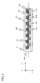
- Fig. 2 is illustrated a state of arrangement of the fluorescent beads in the flow path.
- the beads 41 of which surfaces have already been processed and non-processed usual beads 42 are arranged alternatively in such a way that the targets to be inspected such as DNA, protein or antibodies added with fluorescent substances are coupled to each other.
- the liquid becoming the target to be inspected such as DNA, protein or antibodies added with fluorescent substances flows along the flow path flowing from the left side to the right side as seen in Fig. 2, the liquid forms a large stream in a y-direction while becoming a disturbed flow near the beads, resulting in that the DNA, for example, of the aforesaid inspected item is efficiently hybridized on the surface processed beads.
- the processed beads 41 that may be connected to the inspected items will be further processed such that the substances to be connected for every type of several kinds of DNA, protein or antibodies or the like are adhered to the beads surfaces in compliance with each of the items. Only at least the number of beads processed in this way are prepared and the beads are practically installed in such a way that they may be arranged in the flow path shown in Fig. 2 under a predetermined order, i.e. 41 A, 41B, 41C and 41D.... A location of the end bead 41 A is fixed with a stopper 44 having several small holes made to cause liquid to be passed.
- some dummy beads 42 are arranged to hold the inspected beads.
- An excitation light emitted from the light source 1 such as an excitation light 15 shown in Fig. 2 passes through the beam forming means 11 and the objective lens 14 to radiate onto the beads in such a shape as one in which it is long in an x-direction perpendicular to a large flow y-direction in the flow path.
- a stage 6 shown in Fig. 1 that can be moved mounts a sample having some beads arranged in the flow path and the stage can be moved in at least y-direction through a mechanism, not shown. Since the stage receives an instruction issued by a control circuit 5 to move in beads arrangement direction, the excitation light 15 scans the arranged beads in sequence and radiates thereto.
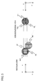
- Fig. 3 is an enlarged view for showing the bead and the excitation light 15 for use in radiating against the bead. They are adjusted such that a center of the excitation light in its longitudinal direction and a center of the groove may coincide to each other.
- a width W of the groove and a bead diameter D have a following relation of: W/2 ⁇ D ⁇ W and they are arranged such that an order of the beads may not be disturbed.
- a length L of the excitation light in its longitudinal direction has a following relation so as to cause the locations near their top portions may always be radiated even if the beads are arranged in a zigzag form. That is, detection of an area 101 on the bead shown in Fig. 3 reduces interference with a detection of the adjoining beads and causes a sufficient detection area to be assured.
- Fig. 3 although the dummy beads are arranged alternately, when the dummy beads are not present, but when there are provided all the meaningful beads contributing to the detection, it becomes important to arrange the detection area shown in Fig. 3 for eliminating any influence of interference of the adjoining beads.
- a length of the detection area 101 in a scanning direction in Fig. 3 is designated by Ly and a length of the excitation light in its longitudinal direction is designated by Lx.
- the value Ly will be determined by a method to be described later.
- the value Lx will be described.
- the value Lx is less than the width W of the groove. Even if the length is made to be longer than this value, fluorescence detection intensity becomes relatively low, resulting in that this variation provides no meaning at all.
- the width W of the groove is set to be substantially equal to the bead diameter D, it would be satisfactory to set a width more than 1/3 of the bead diameter. Setting the value Lx to an excessive low value under a condition in which the groove width W is larger than the bead diameter D causes the excitation light not to enable the center of the bead to be radiated and a detection precision is reduced.
- a laser beam emitted from the laser light source 1 has a diameter of about 1 mm, so that a beam diameter is expanded from several millimeters to several tens of millimeters through a beam expander 111.
- the expanded beam shows that a longitudinal direction of a spot near a focal point 115 of a cylindrical lens 112 keeps a length ranging from several millimeters to several tens of millimeters and its narrow direction is narrowed to about sub-millimeters through the cylindrical lens.
- This focal point position occupies a substantial conjugate positional relation with the top point of the inspected bead through the objective lens. Accordingly, the laser beam passed through the beam forming optical system 11 radiates a fine excitation light elongated in a direction perpendicular to a direction of groove onto the beads.
- the excitation light passed through the beam forming optical system is absorbed by the fluorescent substance added to the beads to generate fluorescence.
- the generated fluorescence passes through the objective lens, passes through the wavelength selection beam splitter and the fluorescence is detected by a high sensitivity light detector 3 through lenses 31, 33.
- the high sensitivity light detector is set such that a photo-diode and a photo-multi-processor and the like are selected according to an intensity of the detected light intensity.
- the front surface of the high sensitivity light detector is provided with a slit aperture at a location where it is conjugate with surfaces of the beads so as to cause only a fluorescence emitted from the location where excitation light radiates to be detected.
- the interference filter 34 shown in Fig. 1 is used when a sufficient removal of excitation light cannot be attained only through the wavelength selection beam splitter. Almost of all the excitation light do not reach to the high sensitivity light detector due to this filter. Further, in order to eliminate either a reflection of the excitation light from the groove bottom part of the bead samples or the lid surface of the groove or some optical parts such as lenses in the midway part of the light path and fluorescence, there is sometimes provided a noise elimination spatial filter for use in eliminating these noises.
- the excitation light for use in radiating against the beads in its fine elongated form returns back to its light path from which the excitation light came. Accurate detection of the location where the beads are radiated with the light could be carried out by applying the method described below. That is, the returning excitation light reflected by the wavelength selection beam splitter shown in Fig. 1 is curved upwardly in its light path by the beam splitter 12, passes through the lens 21 and then the light is received by the position sensor 2.
- Fig. 5 illustrates architecture of the position sensor 2.
- the position sensor 2 is separated into two detector elements 201, 202 at its central part and then a light intensity detected at each of the right and left light receiving surfaces is independently calculated.
- the light 2100 having the excitation light normally reflected at the bead surfaces and directly incident to the position sensor and the light 2101 or the like reflected at the location other than that of the beads are incident to the receiving surfaces.
- the light 2100 normally reflected at the beads and returned back is a fine illuminating light elongated in an x direction, it is elongated in the y direction on the position sensor because the position sensor and the bead surfaces have a Fourier conversion relation.
- the two elements 201, 202 of the position sensor are arranged in this longitudinal direction.
- the excitation light normally reflected with the beads is set such that a center of the distribution of intensity comes to an intermediate position between the two elements 201, 202 of the position sensor.
- the excitation light is displaced from the top portions of the beads to the direction of +y and radiated, the light is shifted toward the two elements 201 of the position sensor and received, resulting in that when the light is displaced in -y direction, the light is shifted to the element 202.
- a difference signal Sp and a sum signal S PS can be attained through a relative scanning of the excitation light and the beads as shown in a lower graph in Fig. 6 through a circuit for attaining the difference signal Sp and the sum signal S PS in reference to the detected signals of the two elements 201, 202.
- a waveform shown at the lower graph of Fig. 6 is generated.
- the excitation light is scanned in a relative manner, and a time in which the light passes near the center of the beads as described below can be made apparent in reference to the difference signals S P1 , S P2 and S P3 and the sum signals S PS1 , S PS2 and S PS3 . That is, a timing in which the signals S PS1 , S PS2 and S PS3 are more than a certain level and the signals S P1 , S P2 and S P3 become 0 is detected by a processing circuit. Fluorescence detection intensities between time widths ⁇ t before and after this time are multiplied.
- the fluorescent signals S L1 , S L2 and S L3 are detected by the high intensity light detector 3 at a timing having the highest fluorescent detection between the times ⁇ t, i.e. at a location where the excitation light radiates against a part near the upper portions of the beads, resulting in that a quite accurate fluorescent detection can always be carried out.
- the fluorescent intensity of each of the beads can be obtained when the fluorescent detection signals S L are accumulated in sequence in a memory, a plurality of data corresponding to the time widths ⁇ t determined mainly based on an address in the memory when the center of the beads is detected are taken out and their sums are taken.
- the polarized beam splitter 12 is set such that a polarizing direction of the linear polarization of the laser light source 1 is a z direction. Since the laser beam of the linear polarization is incident to the polarized beam splitter 12 as a P polarization, the beam may pass through it by approximately 100%.
- the linear polarization of the passed S-polarization passes through the objective lens 14, it passes through 1/4 wavelength plate 22 to become a circular polarization, radiates against the beads and when the reflected light passes again through the 1/4 wavelength plate 22 from an opposite direction, it is changed into an S-polarization and returns back to the polarization beam splitter 12.
- the linear polarization of this S-polarization is reflected by the polarization beam splitter by approximately 100% and reaches to the position sensor 2.
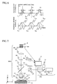
- Fig. 7 illustrates another preferred embodiment of the present invention.
- the component elements in Fig. 7 having the same reference numbers as those shown in Fig. 1 denote the same component elements.
- a light source 1' an electrical discharging lamp such as a mercury lamp is used.
- a fine elongated sight view diaphragm (1 15 in Fig. 4) is inserted into a position in conjugate with a position of each of the beads in addition to the cylindrical lens for use in forming a fine elongated beam.
- a laser light source 20 for accurately setting a center of the bead is separately arranged because a directivity of the excitation light cannot be attained like that of the laser beam.
- the light emitted from this laser light source is weak as compared with that of the excitation light, and its wavelength is long.
- its wavelength is a long wavelength different from a fluorescence wavelength in the way that it may not become a noise at the time of fluorescent detection.
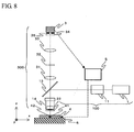
- Fig. 8 shows a still another preferred embodiment of the present invention.
- the same reference numbers as those shown in Fig. 1 denote the same component elements.
- a position of the regular reflected light is not carried out. That is, a detection timing for the bead is determined under application of only the detecting signal of the high sensitivity light detector 3.
- the detection can be attained only through application of the fluorescence detection signal.
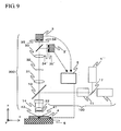
- Fig. 9 shows a still further preferred embodiment of the present invention.
- the excitation lights having more than two types of wavelength are applied.
- the light source 1 is a light source with a wavelength of 635 nm and the light source 1' is a light source with a wavelength of 532 nm.
- a wavelength selection splitter 17 synthesizes these lights having two different wavelengths.
- the beam forming optical system 11 causes both lights to be changed into a fine elongated shape on the beads. Since the beads are added with more than two kinds of fluorescence, each of the fluorescent substances may absorb much amount of excitation light with the corresponding excitation light to emit fluorescence.
- the produced fluorescence is reflected and passed according to each fluorescence by the wavelength selection beam splitter 36 and detected by the high sensitivity light detectors 3, 3' corresponding to each of the fluorescence, thereby a plurality of fluorescence can be separately detected. It is naturally to say in this case that the most-preferable interference filters 35, 35' are applied in compliance with a wavelength of each of the fluorescence.
- the present invention it becomes possible to detect fluorescence easily and accurately against the sample having some beads added with fluorescent substances, becomes possible to perform a convenient and less-expensive inspection and so the beads may become an effective tool for a user participated in research and development in the filed of a life science. It is certain that the present invention may contribute to a development in the field of the life science and a development in medical diagnosis or medicines and the like.
Landscapes
- Health & Medical Sciences (AREA)
- Chemical & Material Sciences (AREA)
- Immunology (AREA)
- Physics & Mathematics (AREA)
- Analytical Chemistry (AREA)
- Life Sciences & Earth Sciences (AREA)
- Biochemistry (AREA)
- General Health & Medical Sciences (AREA)
- General Physics & Mathematics (AREA)
- Pathology (AREA)
- Nuclear Medicine, Radiotherapy & Molecular Imaging (AREA)
- Optics & Photonics (AREA)
- Chemical Kinetics & Catalysis (AREA)
- Dispersion Chemistry (AREA)
- Investigating, Analyzing Materials By Fluorescence Or Luminescence (AREA)
- Optical Measuring Cells (AREA)
Applications Claiming Priority (2)
| Application Number | Priority Date | Filing Date | Title |
|---|---|---|---|
| JP2003415376 | 2003-12-12 | ||
| JP2003415376A JP4041458B2 (ja) | 2003-12-12 | 2003-12-12 | 蛍光ビーズ検出方法及び蛍光ビーズ検出装置 |
Publications (3)
| Publication Number | Publication Date |
|---|---|
| EP1541993A2 true EP1541993A2 (fr) | 2005-06-15 |
| EP1541993A3 EP1541993A3 (fr) | 2005-08-10 |
| EP1541993B1 EP1541993B1 (fr) | 2008-07-30 |
Family
ID=34510573
Family Applications (1)
| Application Number | Title | Priority Date | Filing Date |
|---|---|---|---|
| EP04029200A Expired - Lifetime EP1541993B1 (fr) | 2003-12-12 | 2004-12-09 | Méthode et dispositif de détection de particules fluorescentes |
Country Status (4)
| Country | Link |
|---|---|
| US (1) | US20050130325A1 (fr) |
| EP (1) | EP1541993B1 (fr) |
| JP (1) | JP4041458B2 (fr) |
| DE (1) | DE602004015398D1 (fr) |
Cited By (3)
| Publication number | Priority date | Publication date | Assignee | Title |
|---|---|---|---|---|
| USD601712S1 (en) | 2005-01-07 | 2009-10-06 | Universal Bio Research Co., Ltd. | Carrier enclosing tip |
| CN102460170A (zh) * | 2009-04-20 | 2012-05-16 | 环球生物研究株式会社 | 生物相关物质测定用管及定量系统 |
| US8828331B2 (en) | 2005-09-05 | 2014-09-09 | Universal Bio Research Co., Ltd. | Various-substance holder, various-substance holder treating apparatus, and various-substance holder treating method |
Families Citing this family (6)
| Publication number | Priority date | Publication date | Assignee | Title |
|---|---|---|---|---|
| TWI402505B (zh) | 2004-12-10 | 2013-07-21 | Universal Bio Research Co Ltd | 封入生物材料固定用載體之滴尖,生物材料固定用載體之處理裝置及其處理方法 |
| TWI411778B (zh) * | 2005-01-07 | 2013-10-11 | Universal Bio Research Co Ltd | 內封載體之管片、載體處理裝置,以及載體處理方法 |
| JP4655088B2 (ja) * | 2005-05-20 | 2011-03-23 | 日立化成工業株式会社 | 生化学物質の分析方法 |
| JP4955244B2 (ja) * | 2005-09-27 | 2012-06-20 | 横河電機株式会社 | バイオチップ読み取り装置およびバイオチップ読み取り方法 |
| US9061109B2 (en) * | 2009-07-22 | 2015-06-23 | Accuvein, Inc. | Vein scanner with user interface |
| US10324041B2 (en) * | 2016-12-21 | 2019-06-18 | Abbott Japan Co., Ltd. | Optical imaging system using lateral illumination for digital assays |
Family Cites Families (10)
| Publication number | Priority date | Publication date | Assignee | Title |
|---|---|---|---|---|
| JP3187129B2 (ja) * | 1992-04-01 | 2001-07-11 | シスメックス株式会社 | 粒子分析装置 |
| JP3231134B2 (ja) * | 1993-05-11 | 2001-11-19 | 住友化学工業株式会社 | 微粒子計測方法およびそのための装置 |
| GB9418981D0 (en) * | 1994-09-21 | 1994-11-09 | Univ Glasgow | Apparatus and method for carrying out analysis of samples |
| JPH11149015A (ja) * | 1997-11-14 | 1999-06-02 | Nitto Denko Corp | 積層波長板、円偏光板及び液晶表示装置 |
| JP3944996B2 (ja) * | 1998-03-05 | 2007-07-18 | 株式会社日立製作所 | Dnaプローブアレー |
| CA2640578A1 (fr) * | 1998-05-14 | 1999-11-18 | Luminex Corporation | Systeme de diagnostic multi-analyse et son procede de mise en oeuvre informatique |
| JP2000199855A (ja) * | 1998-11-02 | 2000-07-18 | Olympus Optical Co Ltd | 走査型光学顕微鏡装置 |
| ATE508200T1 (de) * | 1999-02-23 | 2011-05-15 | Caliper Life Sciences Inc | Sequenzierung durch inkorporation |
| US7247489B2 (en) * | 2002-03-11 | 2007-07-24 | Auburn University | Ion-detecting microspheres and methods of use thereof |
| WO2003093795A2 (fr) * | 2002-05-03 | 2003-11-13 | Immunivest Corporation | Dispositif et procede d'imagerie de cellules analytiques |
-
2003
- 2003-12-12 JP JP2003415376A patent/JP4041458B2/ja not_active Expired - Fee Related
-
2004
- 2004-12-08 US US11/006,624 patent/US20050130325A1/en not_active Abandoned
- 2004-12-09 DE DE602004015398T patent/DE602004015398D1/de not_active Expired - Lifetime
- 2004-12-09 EP EP04029200A patent/EP1541993B1/fr not_active Expired - Lifetime
Cited By (8)
| Publication number | Priority date | Publication date | Assignee | Title |
|---|---|---|---|---|
| USD601712S1 (en) | 2005-01-07 | 2009-10-06 | Universal Bio Research Co., Ltd. | Carrier enclosing tip |
| US8828331B2 (en) | 2005-09-05 | 2014-09-09 | Universal Bio Research Co., Ltd. | Various-substance holder, various-substance holder treating apparatus, and various-substance holder treating method |
| US8852525B2 (en) | 2005-09-05 | 2014-10-07 | Universal Bio Research Co., Ltd. | Various-substance holder, various-substance holder treating apparatus, and various-substance holder treating method |
| US9260744B2 (en) | 2005-09-05 | 2016-02-16 | Universal Bio Research Co., Ltd. | Various-substance holder, various-substance holder treating apparatus, and various-substance holder treating method |
| CN102460170A (zh) * | 2009-04-20 | 2012-05-16 | 环球生物研究株式会社 | 生物相关物质测定用管及定量系统 |
| EP2434284A4 (fr) * | 2009-04-20 | 2012-11-14 | Universal Bio Research Co Ltd | Tube pour mesurer une substance biologique et système de quantification |
| CN102460170B (zh) * | 2009-04-20 | 2014-11-05 | 环球生物研究株式会社 | 生物相关物质测定用管及定量系统 |
| US9778253B2 (en) | 2009-04-20 | 2017-10-03 | Universal Bio Research Co., Ltd. | Tube for measuring bio-related substance and quantifying system |
Also Published As
| Publication number | Publication date |
|---|---|
| JP2005172699A (ja) | 2005-06-30 |
| EP1541993B1 (fr) | 2008-07-30 |
| EP1541993A3 (fr) | 2005-08-10 |
| US20050130325A1 (en) | 2005-06-16 |
| JP4041458B2 (ja) | 2008-01-30 |
| DE602004015398D1 (de) | 2008-09-11 |
Similar Documents
| Publication | Publication Date | Title |
|---|---|---|
| CN101421598B (zh) | 用于同时实时监控来自复合源的光信号的方法和系统 | |
| JP6505260B2 (ja) | 放射線搬送体および光学センサ中での放射線搬送体の使用 | |
| US8686376B2 (en) | Microarray characterization system and method | |
| RU2609184C2 (ru) | Устройство, применяемое для детектирования аффинностей связывания | |
| EP1190232A1 (fr) | Lecteur pour microplaques | |
| US8314407B2 (en) | Optical illumination apparatus for illuminating a sample with a line beam | |
| EP1174706A3 (fr) | Spectrométre rapide à haut rendiment et procédé | |
| JP2002540423A (ja) | 分析システム | |
| JP4259762B2 (ja) | 光を検出するための光学的構成 | |
| BRPI0714458A2 (pt) | sistema de detecÇço para detectar locais de luminescÊncia sobre um substrato, compensador àptico, mÉtodo para detectar locais de radiaÇço sobre um substrato, mÉtodo baseado em computador para projetar um compensador àptico, produto de programa de computador, dispositivo de armazenagem de dados legÍveis por mÁquina, e, transmissço do produto de programa de computador | |
| KR20050088782A (ko) | 광검출 장치 | |
| EP1541993B1 (fr) | Méthode et dispositif de détection de particules fluorescentes | |
| CN111349553A (zh) | 一种基因测序仪光学系统 | |
| US8421000B2 (en) | Beam shaping without introducing divergence within a light beam | |
| US20040021867A1 (en) | Device for carrying out biochemical fluorescence tests | |
| KR20070095306A (ko) | 시스템, 조명 서브 시스템 및 형광원에 의해 방출된 형광을증가하는 방법 | |
| WO2003038413A1 (fr) | Appareil permettant d'analyser l'image fluorescente d'une biopuce | |
| WO2004036195A1 (fr) | Analyse fluorimetrique multiparametre dans un dispositif multifocal massivement parallele, et son utilisation | |
| JPH11173987A (ja) | マイクロタイタビューア | |
| WO2009144614A1 (fr) | Appareil et procédé d'éclairage optique | |
| JP2004191252A (ja) | 蛍光読み取り装置 | |
| GB2395267A (en) | Assay analysis | |
| CN101903761A (zh) | 检测系统和方法 | |
| JP2001249077A (ja) | 複数の試料点から蛍光を検出するための装置 | |
| EP2163885A1 (fr) | Système et procédé de caractérisation de microréseau |
Legal Events
| Date | Code | Title | Description |
|---|---|---|---|
| PUAI | Public reference made under article 153(3) epc to a published international application that has entered the european phase |
Free format text: ORIGINAL CODE: 0009012 |
|
| 17P | Request for examination filed |
Effective date: 20041209 |
|
| AK | Designated contracting states |
Kind code of ref document: A2 Designated state(s): AT BE BG CH CY CZ DE DK EE ES FI FR GB GR HU IE IS IT LI LT LU MC NL PL PT RO SE SI SK TR |
|
| AX | Request for extension of the european patent |
Extension state: AL BA HR LV MK YU |
|
| PUAL | Search report despatched |
Free format text: ORIGINAL CODE: 0009013 |
|
| RIC1 | Information provided on ipc code assigned before grant |
Ipc: 7G 01N 21/64 A Ipc: 7G 01N 15/14 B |
|
| AK | Designated contracting states |
Kind code of ref document: A3 Designated state(s): AT BE BG CH CY CZ DE DK EE ES FI FR GB GR HU IE IS IT LI LT LU MC NL PL PT RO SE SI SK TR |
|
| AX | Request for extension of the european patent |
Extension state: AL BA HR LV MK YU |
|
| AKX | Designation fees paid |
Designated state(s): DE FR GB |
|
| 17Q | First examination report despatched |
Effective date: 20060516 |
|
| GRAP | Despatch of communication of intention to grant a patent |
Free format text: ORIGINAL CODE: EPIDOSNIGR1 |
|
| GRAS | Grant fee paid |
Free format text: ORIGINAL CODE: EPIDOSNIGR3 |
|
| GRAA | (expected) grant |
Free format text: ORIGINAL CODE: 0009210 |
|
| AK | Designated contracting states |
Kind code of ref document: B1 Designated state(s): DE FR GB |
|
| REG | Reference to a national code |
Ref country code: GB Ref legal event code: FG4D |
|
| REF | Corresponds to: |
Ref document number: 602004015398 Country of ref document: DE Date of ref document: 20080911 Kind code of ref document: P |
|
| PLBE | No opposition filed within time limit |
Free format text: ORIGINAL CODE: 0009261 |
|
| STAA | Information on the status of an ep patent application or granted ep patent |
Free format text: STATUS: NO OPPOSITION FILED WITHIN TIME LIMIT |
|
| 26N | No opposition filed |
Effective date: 20090506 |
|
| PGFP | Annual fee paid to national office [announced via postgrant information from national office to epo] |
Ref country code: DE Payment date: 20131220 Year of fee payment: 10 Ref country code: GB Payment date: 20131219 Year of fee payment: 10 |
|
| PGFP | Annual fee paid to national office [announced via postgrant information from national office to epo] |
Ref country code: FR Payment date: 20131220 Year of fee payment: 10 |
|
| REG | Reference to a national code |
Ref country code: DE Ref legal event code: R119 Ref document number: 602004015398 Country of ref document: DE |
|
| GBPC | Gb: european patent ceased through non-payment of renewal fee |
Effective date: 20141209 |
|
| REG | Reference to a national code |
Ref country code: FR Ref legal event code: ST Effective date: 20150831 |
|
| PG25 | Lapsed in a contracting state [announced via postgrant information from national office to epo] |
Ref country code: DE Free format text: LAPSE BECAUSE OF NON-PAYMENT OF DUE FEES Effective date: 20150701 Ref country code: GB Free format text: LAPSE BECAUSE OF NON-PAYMENT OF DUE FEES Effective date: 20141209 |
|
| PG25 | Lapsed in a contracting state [announced via postgrant information from national office to epo] |
Ref country code: FR Free format text: LAPSE BECAUSE OF NON-PAYMENT OF DUE FEES Effective date: 20141231 |