EP1542004A1 - Procédé et dispositif pour l'éxamination non-destructive, ultrasonore des pièces symétriques rotatives - Google Patents
Procédé et dispositif pour l'éxamination non-destructive, ultrasonore des pièces symétriques rotatives Download PDFInfo
- Publication number
- EP1542004A1 EP1542004A1 EP04023873A EP04023873A EP1542004A1 EP 1542004 A1 EP1542004 A1 EP 1542004A1 EP 04023873 A EP04023873 A EP 04023873A EP 04023873 A EP04023873 A EP 04023873A EP 1542004 A1 EP1542004 A1 EP 1542004A1
- Authority
- EP
- European Patent Office
- Prior art keywords
- workpieces
- transport
- rollers
- testing
- transport path
- Prior art date
- Legal status (The legal status is an assumption and is not a legal conclusion. Google has not performed a legal analysis and makes no representation as to the accuracy of the status listed.)
- Granted
Links
- 238000012360 testing method Methods 0.000 title claims abstract description 58
- 238000000034 method Methods 0.000 title claims abstract description 29
- 238000002604 ultrasonography Methods 0.000 title claims description 13
- 239000007788 liquid Substances 0.000 claims abstract description 15
- 230000007547 defect Effects 0.000 claims description 10
- 239000004033 plastic Substances 0.000 claims description 7
- 230000002093 peripheral effect Effects 0.000 claims description 6
- 238000009659 non-destructive testing Methods 0.000 claims description 5
- 230000002950 deficient Effects 0.000 claims description 4
- 125000004122 cyclic group Chemical group 0.000 claims description 3
- 229920001296 polysiloxane Polymers 0.000 claims description 2
- 239000012780 transparent material Substances 0.000 claims 1
- 230000032258 transport Effects 0.000 description 87
- 239000000523 sample Substances 0.000 description 8
- 230000001154 acute effect Effects 0.000 description 6
- 239000000463 material Substances 0.000 description 5
- 238000004519 manufacturing process Methods 0.000 description 4
- 238000005096 rolling process Methods 0.000 description 4
- 230000004323 axial length Effects 0.000 description 3
- 238000007599 discharging Methods 0.000 description 3
- 230000004888 barrier function Effects 0.000 description 2
- 230000008878 coupling Effects 0.000 description 2
- 238000010168 coupling process Methods 0.000 description 2
- 238000005859 coupling reaction Methods 0.000 description 2
- 230000009286 beneficial effect Effects 0.000 description 1
- 238000004590 computer program Methods 0.000 description 1
- 238000013461 design Methods 0.000 description 1
- 238000002592 echocardiography Methods 0.000 description 1
- 230000002996 emotional effect Effects 0.000 description 1
- 238000005516 engineering process Methods 0.000 description 1
- 230000001939 inductive effect Effects 0.000 description 1
- 238000007689 inspection Methods 0.000 description 1
- 238000005259 measurement Methods 0.000 description 1
- 239000002184 metal Substances 0.000 description 1
- 230000008569 process Effects 0.000 description 1
- 238000012545 processing Methods 0.000 description 1
- 238000000275 quality assurance Methods 0.000 description 1
- 238000012216 screening Methods 0.000 description 1
- 238000000926 separation method Methods 0.000 description 1
- 230000007480 spreading Effects 0.000 description 1
- 238000003892 spreading Methods 0.000 description 1
- 238000004154 testing of material Methods 0.000 description 1
- 238000009333 weeding Methods 0.000 description 1
Images



Classifications
-
- G—PHYSICS
- G01—MEASURING; TESTING
- G01N—INVESTIGATING OR ANALYSING MATERIALS BY DETERMINING THEIR CHEMICAL OR PHYSICAL PROPERTIES
- G01N29/00—Investigating or analysing materials by the use of ultrasonic, sonic or infrasonic waves; Visualisation of the interior of objects by transmitting ultrasonic or sonic waves through the object
- G01N29/22—Details, e.g. general constructional or apparatus details
- G01N29/26—Arrangements for orientation or scanning by relative movement of the head and the sensor
- G01N29/27—Arrangements for orientation or scanning by relative movement of the head and the sensor by moving the material relative to a stationary sensor
-
- G—PHYSICS
- G01—MEASURING; TESTING
- G01N—INVESTIGATING OR ANALYSING MATERIALS BY DETERMINING THEIR CHEMICAL OR PHYSICAL PROPERTIES
- G01N29/00—Investigating or analysing materials by the use of ultrasonic, sonic or infrasonic waves; Visualisation of the interior of objects by transmitting ultrasonic or sonic waves through the object
- G01N29/22—Details, e.g. general constructional or apparatus details
- G01N29/225—Supports, positioning or alignment in moving situation
Definitions
- the ultrasonic test as e.g. from EP 0 420 639 A2 is known, the recognition allows both near-surface as well as included in the workpiece error.
- the ultrasonic test becomes every workpiece to be tested clamped or inserted in a rotating device and subsequently rotating, for example after the ultrasonic pulse echo Procedure, tested.
- Such an ultrasonic test is extremely sensitive. An interpretation of the gained with it Results can be difficult at times.
- the piecewise examination the workpieces requires a high cost and time.
- the object of the invention is the disadvantages of the prior art to eliminate the technology. It is intended in particular a method and a device can be provided with which a most efficient testing of a large number of workpieces is possible by ultrasonic method. After another The goal is to perform the ultrasound test as possible that safe and reliable faulty workpieces can be distinguished from error-free.
- the workpieces fed gravitationally You can, for example, rolling in a sloping towards the transport device channel be supplied. In this case always arrives new workpiece on the transport device, if one previously supplied workpiece already one of its length corresponding Has covered the way on the transport route.
- several workpieces are simultaneously in a transport channel provided with a rotation device transported.
- the workpieces by means of the rotation device be rotated simultaneously and in the same direction.
- the Workpieces can be tested according to different criteria become.
- the proposed method is particularly efficient. In particular, it is no longer necessary, each Clamp the workpiece separately in a rotary device, subsequently check and then back out of the rotary device exit.
- the Workpieces cyclically transported along the transport route. This facilitates the process management. Recognized as faulty Workpieces can be assigned to a specific clock and as a result simply be singled out.
- a intermittent feed remain the workpieces for a given Duration in the transport device at a certain Place. They are rotated at this location and can get one there Be subjected to examination.
- the workpieces an intervening in the conveyor trough pushing means intermittently be transported.
- the pushing means can be so in particular be executed that it is the axial length of the workpieces corresponds.
- the feed means the workpieces even with a rotation in the transport direction safely and reliably kept in place. This allows a particularly reliable test.
- the proposed procedure is particularly suitable for rolls with a convex or convex lateral surface.
- transport chute is within the meaning of the present To understand the invention in general. Such a transport channel does not have to have a closed bottom, but only like a gutter a transport function along a Fulfill transport route.
- the workpieces may be substantially coaxial with the rollers be transported in the transport channel.
- the workpieces are frictionally engaged with the rollers and become by their rotation during transport around the axis rotates. It is expediently a tendency and / or Spread the roll axes adjusted so that the Werkstükke at a given speed along the transport path be transported.
- the inclination and / or the Spread of the roll axes is chosen so that in total an inclination of the transport channel formed between the rollers from a feeding point to a discharge point of the workpieces results.
- the proposed transport device is easy to set up. It is susceptible to interference and can be especially also immersed in a liquid without problems operate.
- the workpieces can be provided on at least one of the transport route Ultrasonic testing be passed. For ultrasonic testing, it is not absolutely necessary to move the ultrasonic testing equipment.
- the workpieces can also by means of a conveyor belt forming a wall of the conveyor belt be rotated about its axis.
- the axis stands the rotationally symmetrical workpieces perpendicular to the transport direction.
- the transport takes place in this embodiment expediently intermittently by means of the conveyor trough engaging feed means.
- the pushing means keep in this Case the rotating workpieces each for a particular Time duration in a predetermined position in the transport direction. As long as the workpieces are held in this position is, for example, a test by means of ultrasonic devices possible along a surface of the be moved to the workpiece to be tested.
- the workpieces on the transport path by means of a first ultrasonic testing device checked for surface defects.
- the workpieces can on the transport also by means of a second Ultraschallprüf adopted checked for errors included in the workpiece become. With the proposed 2-fold exam can safe and reliable all relevant defects of the workpiece be recognized.
- faulty workpieces identified and subsequently rejected It is in particular, it is also possible to workpieces with surface defects and workpieces with internal defects weed out separately. Such a separation of Separated workpieces depending on the type of identified Mistakes can be made with regard to quality assurance measures be beneficial.
- the workpieces by means of a, preferably electric motor driven, conveying device led away and lifted out of the liquid.
- a, preferably electric motor driven, conveying device led away and lifted out of the liquid.
- those identified as defective Workpieces after lifting out of the liquid discarded. This facilitates the handling of the rejected Workpieces.
- the proposed device allows an efficient ultrasonic testing a variety of workpieces.
- the ultrasound examination can be partially or fully automatic. This is the first time a routine ultrasonic test in the mass production of workpieces possible.
- a device for each other following feeding of the workpieces to the transport device and / or a device for removing the workpieces from provided the transport device enable automated operation.
- the means for supplying the Workpieces a sloping towards the transport device Channel up.
- the channel can have an adjustable width have, so that rolls of a different length can be fed rolling to the transport device.
- the Feeding trough can be designed so that at the same time several workpieces are receivable.
- the rotation device is suitably designed so that so that the workpieces be rotated simultaneously and in the same direction. This allows a uniform and simultaneous test of several Workpieces.
- the proposed device is special easy to set up. It is not for rotation of the workpieces For each workpiece a separate rotation device required.
- a device for cyclically transporting the workpieces along provided the transport route. It is therefore possible the workpieces rotate for the duration of the test on a certain predetermined place to keep on the transport route. This allows in particular a non-cylindrical test rotationally symmetrical workpieces, for example of Ton rollers.
- the means for intermittent transport in the conveyor trough engaging pushing means can be selected Be that to the axial length of the workpieces to be tested corresponds.
- This can in particular barrel rollers rotating in a predetermined position to carry out the Inspection to be kept on the transport route.
- the device for intermittent transport expediently has a single Drive device on. This ensures that all workpieces in the same cycle and at the same speed transported cyclically on the transport route become.
- the transport device expediently has two side by side arranged, forming a transport chute, rollers on.
- An intended between the peripheral surfaces of the rollers Distance is adjustable.
- the between the peripheral surfaces of the Rolls selected distance is such that it is in each Case is smaller than the diameter of the transported Workpieces.
- a tilt and / or spread the roll axes adjustable By a suitable attitude the inclination and / or spreading of the roll axes, can a predetermined transport speed of the workpieces along of the transport path are set.
- a drive device provided for the same direction rotating the rollers. It may conveniently be one outside the container arranged to act electric motor, which via a V-belt with drive pulleys provided on the rollers connected is.
- the transport device may also have a conveyor belt.
- the conveyor belt is expediently used for simultaneous and same-way rotation of a plurality of on the transport route located workpieces.
- the workpieces are in this Case with its axis of rotation perpendicular to the transport direction.
- the conveyor trough can consist of two obliquely one another Walls are formed, whereby one of the walls by the Conveyor belt is formed. The other wall can be supported serve the workpieces.
- the rollers or the conveyor belt are made a material substantially transparent to ultrasound, preferably made of plastic or rubber.
- the ultrasound examination avoided. It can be a very exact one Ultrasonic testing be performed.
- a peripheral surface of the rollers or the conveyor belt may be made Plastic, rubber or silicone be made. Conveniently, the peripheral surface is made of a material the one frictional contact with the transported Workpieces guaranteed even if oil as a liquid is used.
- first movement device attached first Ultraschallprüf is in the vicinity of the transport path one on a, preferably electric motor driven, first movement device attached first Ultraschallprüf founded for testing for surface defects intended.
- second movement device attached second Ultrasonic testing device for testing on the workpiece enclosed Error be provided.
- the proposed Ultrasonic testing equipment may be conventional ultrasonic heads act by means of the movement device in a suitable position relative to the workpieces to be tested can be made.
- the movement devices are expediently driven by an electric motor. Consequently It is possible to use such a drive by means of a To control microprocessor. For example, for certain given material geometries suitable positions stored for the first and the second ultrasonic testing device become.
- a device for Identifying faulty workpieces provided. It deals for example, this is a computer with a suitable Program for processing of the ultrasonic heads supplied signals. Furthermore, a device for To dispose of faulty workpieces be provided. Such Device is expediently outside the container arranged. The device for discarding may be to conventional electric, hydraulic, pneumatic or magnetic act drivable actuating means. The device for screening can conveniently by means of the aforementioned Computers are controlled. For control can also in a conventional way photocells along the transport path be provided by means of which a clear order the tested workpieces and a rejecting as faulty identified workpieces downstream of the Ultraschallprüf beauen can be effected.
- a controller for automatic, preferably cyclic, transport and control the movement devices provided.
- a Control can be the movements of ultrasonic testing equipment and the cyclic feed movements of the workpieces coordinated, for example by means of a computer program, be performed. This allows a fast and efficient Testing the workpieces.
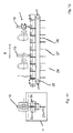
- Figs. 1 to 3 is in a z. B. of metal or plastic manufactured container 1 a generally with the reference numeral 2 designated transport device recorded.
- the Height of the walls of the container 1 is chosen so that the Transport device 2 completely in a recorded in the container 1 Liquid, e.g. As oil, can be submerged.
- the transport device 2 comprises two rollers 3a and 3b, which can be driven by means of a motor 4.
- the rollers 3a, 3b are suitably made of plastic. Your Surface can be made of rubber.
- With the reference number 5 is a means for feeding and with the reference numeral 6 shows a device for discharging rotationally symmetrical trained workpieces 7 referred.
- Along one with the arrow 8 designated transport direction are at one (not shown here) frame electromotively movable Ultraschallprüf prepareden 9a and 9b arranged.
- everyone who Ultrasonic testing device 9a and 9b is a light barrier 10a and 10b assigned. It can be conventional Laser photocells act.
- Downstream of the device 6 for discharging a means 11 for rejecting is erroneous Workpieces 7 provided.
- the device 11 comprises in particular two pushing means 12a and 12b, with which faulty Workpieces 7 from the flow of the removed workpieces 7 can be ejected.
- the pushing means 12a, 12b can For example, it is pneumatic cylinders with push rods act.
- FIG. 2 shows a detailed view according to FIG. 1. It can be seen from FIG. that each of the rollers 3a, 3b respectively in bearing blocks 13a, 13b are included.
- the bearing blocks 13a and 13b can both in the horizontal and in the vertical direction be adjusted.
- the rollers 3a and 3b are over a common V-belt 14 connected to the engine 4.
- the device 5 for feeding has a feed channel 15, whose Width by means of an angle plate 16 is adjustable.
- Fig. 3 shows again in detail the device 11 for separating.
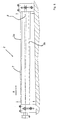
- Fig. 4 to 6 show the transport device 2.
- the rollers 3a, 3b are arranged so that their roll axes in the Top view (see Fig. 5) form an acute angle ⁇ . Of the acute angle ⁇ opens in the transport direction 8.
- a distance between the rollers 3a and 3b is chosen so that he always smaller than the diameter of the workpieces to be tested 7 is. As a result, the two rollers 3a, 3b form a Conveyor trough 17.
- the roll axes of the Rolls 3a and 3b also vertically at a further acute angle ⁇ tilted against each other.
- the angle ⁇ also opens in the transport direction 8.
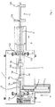
- FIGS. 7 and 8 show in detail one of the ultrasonic testing devices, here the ultrasonic testing device 9a.
- she includes a clamping device 18 for receiving an ultrasonic probe 19.
- the clamping device 18 is a in the Essentially parallel to the roll axes extending axis of rotation rotatable.
- a the clamping device 18 receiving Carrier 20 may be provided with a suitable drive device (here not shown) in the vertical direction as well as in a vertical to the roll axes extending horizontal direction be adjusted.
- suitable electric motors can be provided be, which by means of a (not shown) control device are automatically controllable.
- the photocell 10a is arranged so that the workpieces 7 automatically can be counted.
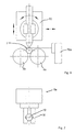
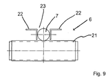
- Fig. 9 shows a cross-sectional view along the section line B-B '.
- the means 6 for discharging consists essentially from a conveyor belt 21 at the top by two another angle plates 22 a discharge channel 23 is formed.
- the function of the first device is the following:
- the rollers 3a and 3b are by means of Motors 4 driven at the same rotational speed. she rotate in the same direction.
- the workpieces 7 are rotating in the transport channel 17 transported along the transport direction 8. there are the workpieces 7 along the transport path to the Ultrasonic testing devices 9a and 9b passed.
- the ultrasonic testing devices 9a and 9b are checked of the workpieces 7 on surface defects as well as in the Workpieces 7 included errors.
- the light barriers 10a and 10b can be the order of the supplied Workpieces 7 are determined. This allows a targeted Rejecting workpieces identified as defective 7 by means of the ejection means 12a and 12b.
- the proposed Device it is also possible in particular, separately Workpieces 7 with surface defects and workpieces 7 with im Weeding out mistakes trapped inside.
- the identification of material defects as well as the sorting can be automated be done using a computer that is suitable is programmed.
- FIGS. 10 to 12 show a second device according to the invention shown. It is different from the first device essentially by the fact that here additionally an generally referred to by the reference numeral 24 feed means for cyclically advancing the workpieces 7 in the transport direction 8 is provided.
- the second device is suitable especially for testing in the form of barrel rollers executed workpieces 7.
- the feed means 24 comprises two rollers 25, around which a belt 26 rotates. At least one of the roles 25 is by means of a (not shown here) intermittently operable Drive device drivable.
- the belt 26 has in regular intervals at its the rollers 25 facing away Outside pushing means 27 on.
- the feed means 24 is with respect to of the rollers 3a, 3b arranged so that the pushing means 27 by a gap formed between the rollers 3a, 3b reach through.
- the thrust means 27 are in their length so Measure that they are attached to a base / top surface of the workpieces 7 abut. As a result, by a movement of the pushing means 27 a movement of the workpieces 7 in the transport direction 8 be enforced.
- the rollers 3a, 3b can be horizontal and parallel to one another be arranged.
- the provided in the first device Tilting the axes of the rollers 3a, 3b relative to each other is not essential here.
- rollers 25 and the belt 26 Other suitable means may be used.
- Belt 26 may be a V-belt, timing belt or chain or the like can be used.
- the workpieces 7 become similar to the first device supplied by the means 5 for feeding. she are rotated by the rollers 3a, 3b. Here are the Workpieces 7 with their base or top surface on a pushing means 27 on. An undesirable movement of the workpieces 7 in or against the transport direction 8 is thus avoided. To ensure this safely, the pushing means 27 can do so be spaced apart that the distance is slightly greater than an axial length of the workpieces 7 is.
- the workpieces 7 are by means of the feed means 24 intermittently in Transport direction 8 transported. They are doing by means of the ultrasonic probes 19 checked for errors. To this Purpose, the ultrasonic probes 19 each with a given speed and on a given path along the surface of the workpieces 7 to be tested automatically emotional.
- the ultrasonic probes are at a suitable electromotive operable movement device appropriate.
- a liquid such as oil
- the removal of the inspected workpieces 7 can take place analogously as in the first device.
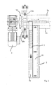
- FIGS. 13 and 14 show a third device according to the invention.
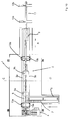
- the first wall 28 is inclined. Attached to it are further rollers 29, around which another conveyor belt 30 rotates. One of the other rollers 29 is driven continuously (not shown here).
- a conveyor side of the conveyor belt 30 forms a second movable wall of the conveyor trough 17. This second movable wall is suitably perpendicular to the first wall 28.
- Feed means 24 is provided in combination with the described Feeding trough 17 is again the one already mentioned above Feed means 24 is provided.
- the feed means 24 is so arranged that the pushing means 27 from above into the conveyor trough 17 engage and reach close to the first wall 28.
- the workpieces 7 are perpendicular with their axis of rotation taken to the transport direction 8 in the conveyor trough 17.
- the function of the third device is as follows:
- the workpieces 7 are provided with a suitable device for Feeding the conveyor trough 17 supplied at a first end.
- the feeding device may be similar to that shown in FIG. 1 be formed device shown, in which case the workpieces However, be supplied standing.
- the continuous movement of the conveyor belt 30 is the Workpiece 7 in a rotational movement about its axis of rotation added.
- the feed means 24 the workpiece 7 Intermittently along the formed by the conveyor trough 17 Transported transport route.
- Along the transport route are provided in predetermined positions the ultrasonic probes 19. They are tested by means of a movement device the workpieces 7 over the surface along a given way moves.
- Along the transport route can several ultrasonic probes 19 for performing different Ultrasonic testing be provided.
Landscapes
- Physics & Mathematics (AREA)
- Health & Medical Sciences (AREA)
- Life Sciences & Earth Sciences (AREA)
- Chemical & Material Sciences (AREA)
- Analytical Chemistry (AREA)
- Biochemistry (AREA)
- General Health & Medical Sciences (AREA)
- General Physics & Mathematics (AREA)
- Immunology (AREA)
- Pathology (AREA)
- Investigating Or Analyzing Materials By The Use Of Ultrasonic Waves (AREA)
Applications Claiming Priority (4)
| Application Number | Priority Date | Filing Date | Title |
|---|---|---|---|
| DE10357596 | 2003-12-08 | ||
| DE2003157596 DE10357596B3 (de) | 2003-12-08 | 2003-12-08 | Verfahren und Vorrichtung zur zerstörungsfreien Prüfung rotationssymmetrischer Werkstücke |
| DE102004023871 | 2004-05-12 | ||
| DE200410023871 DE102004023871A1 (de) | 2004-05-12 | 2004-05-12 | Verfahren und Vorrichtung zur zerstörungsfreien Prüfung rotationssymmetrischer Werkstücke |
Publications (2)
| Publication Number | Publication Date |
|---|---|
| EP1542004A1 true EP1542004A1 (fr) | 2005-06-15 |
| EP1542004B1 EP1542004B1 (fr) | 2010-12-08 |
Family
ID=34524064
Family Applications (1)
| Application Number | Title | Priority Date | Filing Date |
|---|---|---|---|
| EP04023873A Expired - Lifetime EP1542004B1 (fr) | 2003-12-08 | 2004-10-07 | Procédé et dispositif pour l'éxamination non-destructive, ultrasonore des pièces symétriques rotatives |
Country Status (3)
| Country | Link |
|---|---|
| EP (1) | EP1542004B1 (fr) |
| AT (1) | ATE491152T1 (fr) |
| DE (1) | DE502004011971D1 (fr) |
Cited By (2)
| Publication number | Priority date | Publication date | Assignee | Title |
|---|---|---|---|---|
| CN104406817A (zh) * | 2014-11-06 | 2015-03-11 | 攀钢集团矿业有限公司 | 矿粉取样设备、矿粉输送线和矿粉生产系统 |
| US10761065B2 (en) * | 2014-08-12 | 2020-09-01 | Ntn Corporation | Device for inspecting junction-type outer joint member of constant velocity universal joint |
Citations (6)
| Publication number | Priority date | Publication date | Assignee | Title |
|---|---|---|---|---|
| US2525305A (en) * | 1949-08-04 | 1950-10-10 | Crucible Steel Co America | Apparatus for feeding elongated stock to and from fabricating units |
| US2758706A (en) | 1955-03-31 | 1956-08-14 | Frank B Quinlan | Inspection conveying apparatus |
| US3708079A (en) * | 1971-02-12 | 1973-01-02 | Custom Machine Inc | Support for rotating and advancing cylindrical members |
| EP0420639A2 (fr) | 1989-09-29 | 1991-04-03 | Ngk Insulators, Ltd. | Appareil d'essai ultrasonore et automatique pour la détection de défauts dans des balles |
| US5005417A (en) * | 1987-03-31 | 1991-04-09 | Ngk Insulators, Ltd. | Detecting flaws formed in surfaces of rotating members with ultrasonic waves |
| WO2000043769A1 (fr) * | 1999-01-22 | 2000-07-27 | Cfi Ceramics For Industry Gmbh & Co. Kg | Dispositif et procede pour le controle par ultrasons d'elements de roulement |
-
2004
- 2004-10-07 AT AT04023873T patent/ATE491152T1/de active
- 2004-10-07 DE DE502004011971T patent/DE502004011971D1/de not_active Expired - Lifetime
- 2004-10-07 EP EP04023873A patent/EP1542004B1/fr not_active Expired - Lifetime
Patent Citations (6)
| Publication number | Priority date | Publication date | Assignee | Title |
|---|---|---|---|---|
| US2525305A (en) * | 1949-08-04 | 1950-10-10 | Crucible Steel Co America | Apparatus for feeding elongated stock to and from fabricating units |
| US2758706A (en) | 1955-03-31 | 1956-08-14 | Frank B Quinlan | Inspection conveying apparatus |
| US3708079A (en) * | 1971-02-12 | 1973-01-02 | Custom Machine Inc | Support for rotating and advancing cylindrical members |
| US5005417A (en) * | 1987-03-31 | 1991-04-09 | Ngk Insulators, Ltd. | Detecting flaws formed in surfaces of rotating members with ultrasonic waves |
| EP0420639A2 (fr) | 1989-09-29 | 1991-04-03 | Ngk Insulators, Ltd. | Appareil d'essai ultrasonore et automatique pour la détection de défauts dans des balles |
| WO2000043769A1 (fr) * | 1999-01-22 | 2000-07-27 | Cfi Ceramics For Industry Gmbh & Co. Kg | Dispositif et procede pour le controle par ultrasons d'elements de roulement |
Non-Patent Citations (1)
| Title |
|---|
| HEPT- NER/STROPPE: "Magnetische und magnetinduktive Werkstoffprüfung", 1973, pages: 267 - 271 |
Cited By (2)
| Publication number | Priority date | Publication date | Assignee | Title |
|---|---|---|---|---|
| US10761065B2 (en) * | 2014-08-12 | 2020-09-01 | Ntn Corporation | Device for inspecting junction-type outer joint member of constant velocity universal joint |
| CN104406817A (zh) * | 2014-11-06 | 2015-03-11 | 攀钢集团矿业有限公司 | 矿粉取样设备、矿粉输送线和矿粉生产系统 |
Also Published As
| Publication number | Publication date |
|---|---|
| ATE491152T1 (de) | 2010-12-15 |
| DE502004011971D1 (de) | 2011-01-20 |
| EP1542004B1 (fr) | 2010-12-08 |
Similar Documents
| Publication | Publication Date | Title |
|---|---|---|
| DE102022121695B4 (de) | Integrierte Kegelradförder- und -Qualitätserfassungs-Vorrichtung und Verfahren zu deren Verwendung | |
| DE69826158T2 (de) | Inspektionsgerät für das Aussehen von Kapseln | |
| DE60128740T2 (de) | Verfahren zur Identifikation von im wesentlichen fehlerfreien Werkstücken | |
| DE69023867T2 (de) | Automatische Ultraschalltestvorrichtung zum Nachweis von Fehlern in Kugeln. | |
| DE1473688C3 (de) | Verfahren zur zerstörungsfreien Prüfung von Glaserzeugnissen und Vorrichtung zur Durchführung des Verfahrens | |
| DE60317990T2 (de) | Vorrichtung zur Inspektion flacher Tabletten | |
| DE4241985A1 (de) | Vorrichtung zum Prüfen von Tabletten | |
| DE4014130A1 (de) | Vorrichtung zum behandeln von kartenfoermigen gegenstaenden | |
| EP4063015A1 (fr) | Procédé et dispositif de vérification des points de pipettes | |
| EP1542004B1 (fr) | Procédé et dispositif pour l'éxamination non-destructive, ultrasonore des pièces symétriques rotatives | |
| DE4202172C1 (en) | Testing surface and shape of similar small objects e.g. medicinal tabless - directing cameras onto rotatable discs with recesses for objects quality control | |
| EP3744663A1 (fr) | Dispositif d'alimentation et d'évacuation et procédé d'alimentation en pièces à usiner dans une machine-outil et d'évacuation des pièces usinées dans la machine-outil de la machine-outil | |
| DE10103582C2 (de) | Einrichtung für selbsttätig ablaufende Kerbschlagbiegeversuche und Verfahren zur Durchführung derselben | |
| DE10357596B3 (de) | Verfahren und Vorrichtung zur zerstörungsfreien Prüfung rotationssymmetrischer Werkstücke | |
| DE2606977C2 (de) | Vorrichtung zum Aussortieren fehlerhafter kreisförmiger Tabletten | |
| DE69302070T2 (de) | Anlage zur Behandlung, zum Ordnen und zum Sortieren von kurzen zylindrischen Körpern, wie zum Beispiel Kernbrennstofftabletten | |
| DE19827608C1 (de) | Vorrichtung zum Fördern mit Prüfabschnitt | |
| DE102004023871A1 (de) | Verfahren und Vorrichtung zur zerstörungsfreien Prüfung rotationssymmetrischer Werkstücke | |
| DE202004020655U1 (de) | Vorrichtung zur zerstörungsfreien Prüfung rotationssymetrischer Werkstücke | |
| EP1271123B1 (fr) | Procédé et appareil pour tester la qualité d'articles ronds moulés et élastiques | |
| DE2364843A1 (de) | Verfahren und vorrichtung zum automatischen und kontinuierlichen untersuchen von behaeltern | |
| DE102015120426A1 (de) | Vorrichtung und Verfahren zum Vereinzeln und/oder Prüfen von Behältern | |
| EP3644766B1 (fr) | Machine et procédé pour dénoyauter des fruits | |
| DE3007540C2 (de) | Vorrichtung zum Prüfen und Aussortieren von Flaschen in einer Flaschenbehandlungsanlage | |
| WO2011113671A1 (fr) | Dispositif pour orienter des comprimés |
Legal Events
| Date | Code | Title | Description |
|---|---|---|---|
| PUAI | Public reference made under article 153(3) epc to a published international application that has entered the european phase |
Free format text: ORIGINAL CODE: 0009012 |
|
| AK | Designated contracting states |
Kind code of ref document: A1 Designated state(s): AT BE BG CH CY CZ DE DK EE ES FI FR GB GR HU IE IT LI LU MC NL PL PT RO SE SI SK TR |
|
| AX | Request for extension of the european patent |
Extension state: AL HR LT LV MK |
|
| 17P | Request for examination filed |
Effective date: 20050818 |
|
| AKX | Designation fees paid |
Designated state(s): AT BE BG CH CY CZ DE DK EE ES FI FR GB GR HU IE IT LI LU MC NL PL PT RO SE SI SK TR |
|
| 17Q | First examination report despatched |
Effective date: 20070307 |
|
| GRAP | Despatch of communication of intention to grant a patent |
Free format text: ORIGINAL CODE: EPIDOSNIGR1 |
|
| RIC1 | Information provided on ipc code assigned before grant |
Ipc: G01N 29/22 20060101AFI20100323BHEP |
|
| GRAS | Grant fee paid |
Free format text: ORIGINAL CODE: EPIDOSNIGR3 |
|
| GRAA | (expected) grant |
Free format text: ORIGINAL CODE: 0009210 |
|
| AK | Designated contracting states |
Kind code of ref document: B1 Designated state(s): AT BE BG CH CY CZ DE DK EE ES FI FR GB GR HU IE IT LI LU MC NL PL PT RO SE SI SK TR |
|
| REG | Reference to a national code |
Ref country code: GB Ref legal event code: FG4D Free format text: NOT ENGLISH |
|
| REG | Reference to a national code |
Ref country code: CH Ref legal event code: EP |
|
| REG | Reference to a national code |
Ref country code: IE Ref legal event code: FG4D |
|
| REF | Corresponds to: |
Ref document number: 502004011971 Country of ref document: DE Date of ref document: 20110120 Kind code of ref document: P |
|
| REG | Reference to a national code |
Ref country code: NL Ref legal event code: VDEP Effective date: 20101208 |
|
| PG25 | Lapsed in a contracting state [announced via postgrant information from national office to epo] |
Ref country code: BG Free format text: LAPSE BECAUSE OF FAILURE TO SUBMIT A TRANSLATION OF THE DESCRIPTION OR TO PAY THE FEE WITHIN THE PRESCRIBED TIME-LIMIT Effective date: 20110308 Ref country code: SE Free format text: LAPSE BECAUSE OF FAILURE TO SUBMIT A TRANSLATION OF THE DESCRIPTION OR TO PAY THE FEE WITHIN THE PRESCRIBED TIME-LIMIT Effective date: 20101208 Ref country code: FI Free format text: LAPSE BECAUSE OF FAILURE TO SUBMIT A TRANSLATION OF THE DESCRIPTION OR TO PAY THE FEE WITHIN THE PRESCRIBED TIME-LIMIT Effective date: 20101208 Ref country code: SI Free format text: LAPSE BECAUSE OF FAILURE TO SUBMIT A TRANSLATION OF THE DESCRIPTION OR TO PAY THE FEE WITHIN THE PRESCRIBED TIME-LIMIT Effective date: 20101208 Ref country code: NL Free format text: LAPSE BECAUSE OF FAILURE TO SUBMIT A TRANSLATION OF THE DESCRIPTION OR TO PAY THE FEE WITHIN THE PRESCRIBED TIME-LIMIT Effective date: 20101208 Ref country code: CY Free format text: LAPSE BECAUSE OF FAILURE TO SUBMIT A TRANSLATION OF THE DESCRIPTION OR TO PAY THE FEE WITHIN THE PRESCRIBED TIME-LIMIT Effective date: 20101208 |
|
| REG | Reference to a national code |
Ref country code: IE Ref legal event code: FD4D |
|
| PG25 | Lapsed in a contracting state [announced via postgrant information from national office to epo] |
Ref country code: IE Free format text: LAPSE BECAUSE OF FAILURE TO SUBMIT A TRANSLATION OF THE DESCRIPTION OR TO PAY THE FEE WITHIN THE PRESCRIBED TIME-LIMIT Effective date: 20101208 Ref country code: CZ Free format text: LAPSE BECAUSE OF FAILURE TO SUBMIT A TRANSLATION OF THE DESCRIPTION OR TO PAY THE FEE WITHIN THE PRESCRIBED TIME-LIMIT Effective date: 20101208 Ref country code: ES Free format text: LAPSE BECAUSE OF FAILURE TO SUBMIT A TRANSLATION OF THE DESCRIPTION OR TO PAY THE FEE WITHIN THE PRESCRIBED TIME-LIMIT Effective date: 20110319 Ref country code: GR Free format text: LAPSE BECAUSE OF FAILURE TO SUBMIT A TRANSLATION OF THE DESCRIPTION OR TO PAY THE FEE WITHIN THE PRESCRIBED TIME-LIMIT Effective date: 20110309 Ref country code: EE Free format text: LAPSE BECAUSE OF FAILURE TO SUBMIT A TRANSLATION OF THE DESCRIPTION OR TO PAY THE FEE WITHIN THE PRESCRIBED TIME-LIMIT Effective date: 20101208 Ref country code: PT Free format text: LAPSE BECAUSE OF FAILURE TO SUBMIT A TRANSLATION OF THE DESCRIPTION OR TO PAY THE FEE WITHIN THE PRESCRIBED TIME-LIMIT Effective date: 20110408 |
|
| PG25 | Lapsed in a contracting state [announced via postgrant information from national office to epo] |
Ref country code: RO Free format text: LAPSE BECAUSE OF FAILURE TO SUBMIT A TRANSLATION OF THE DESCRIPTION OR TO PAY THE FEE WITHIN THE PRESCRIBED TIME-LIMIT Effective date: 20101208 Ref country code: PL Free format text: LAPSE BECAUSE OF FAILURE TO SUBMIT A TRANSLATION OF THE DESCRIPTION OR TO PAY THE FEE WITHIN THE PRESCRIBED TIME-LIMIT Effective date: 20101208 Ref country code: SK Free format text: LAPSE BECAUSE OF FAILURE TO SUBMIT A TRANSLATION OF THE DESCRIPTION OR TO PAY THE FEE WITHIN THE PRESCRIBED TIME-LIMIT Effective date: 20101208 |
|
| PLBE | No opposition filed within time limit |
Free format text: ORIGINAL CODE: 0009261 |
|
| STAA | Information on the status of an ep patent application or granted ep patent |
Free format text: STATUS: NO OPPOSITION FILED WITHIN TIME LIMIT |
|
| PG25 | Lapsed in a contracting state [announced via postgrant information from national office to epo] |
Ref country code: DK Free format text: LAPSE BECAUSE OF FAILURE TO SUBMIT A TRANSLATION OF THE DESCRIPTION OR TO PAY THE FEE WITHIN THE PRESCRIBED TIME-LIMIT Effective date: 20101208 |
|
| 26N | No opposition filed |
Effective date: 20110909 |
|
| PG25 | Lapsed in a contracting state [announced via postgrant information from national office to epo] |
Ref country code: IT Free format text: LAPSE BECAUSE OF FAILURE TO SUBMIT A TRANSLATION OF THE DESCRIPTION OR TO PAY THE FEE WITHIN THE PRESCRIBED TIME-LIMIT Effective date: 20101208 |
|
| REG | Reference to a national code |
Ref country code: DE Ref legal event code: R097 Ref document number: 502004011971 Country of ref document: DE Effective date: 20110909 |
|
| BERE | Be: lapsed |
Owner name: MADINGER, ANETTE Effective date: 20111031 Owner name: BRAND, RENATE Effective date: 20111031 Owner name: MADINGER, JURGEN Effective date: 20111031 |
|
| PG25 | Lapsed in a contracting state [announced via postgrant information from national office to epo] |
Ref country code: MC Free format text: LAPSE BECAUSE OF NON-PAYMENT OF DUE FEES Effective date: 20111031 |
|
| REG | Reference to a national code |
Ref country code: CH Ref legal event code: PL |
|
| PG25 | Lapsed in a contracting state [announced via postgrant information from national office to epo] |
Ref country code: BE Free format text: LAPSE BECAUSE OF NON-PAYMENT OF DUE FEES Effective date: 20111031 Ref country code: LI Free format text: LAPSE BECAUSE OF NON-PAYMENT OF DUE FEES Effective date: 20111031 Ref country code: CH Free format text: LAPSE BECAUSE OF NON-PAYMENT OF DUE FEES Effective date: 20111031 |
|
| PGFP | Annual fee paid to national office [announced via postgrant information from national office to epo] |
Ref country code: FR Payment date: 20121113 Year of fee payment: 9 Ref country code: DE Payment date: 20120921 Year of fee payment: 9 |
|
| PGFP | Annual fee paid to national office [announced via postgrant information from national office to epo] |
Ref country code: GB Payment date: 20121023 Year of fee payment: 9 |
|
| PGFP | Annual fee paid to national office [announced via postgrant information from national office to epo] |
Ref country code: AT Payment date: 20121022 Year of fee payment: 9 |
|
| PG25 | Lapsed in a contracting state [announced via postgrant information from national office to epo] |
Ref country code: LU Free format text: LAPSE BECAUSE OF NON-PAYMENT OF DUE FEES Effective date: 20111007 |
|
| PG25 | Lapsed in a contracting state [announced via postgrant information from national office to epo] |
Ref country code: TR Free format text: LAPSE BECAUSE OF FAILURE TO SUBMIT A TRANSLATION OF THE DESCRIPTION OR TO PAY THE FEE WITHIN THE PRESCRIBED TIME-LIMIT Effective date: 20101208 |
|
| PG25 | Lapsed in a contracting state [announced via postgrant information from national office to epo] |
Ref country code: HU Free format text: LAPSE BECAUSE OF FAILURE TO SUBMIT A TRANSLATION OF THE DESCRIPTION OR TO PAY THE FEE WITHIN THE PRESCRIBED TIME-LIMIT Effective date: 20101208 |
|
| REG | Reference to a national code |
Ref country code: AT Ref legal event code: MM01 Ref document number: 491152 Country of ref document: AT Kind code of ref document: T Effective date: 20131007 |
|
| GBPC | Gb: european patent ceased through non-payment of renewal fee |
Effective date: 20131007 |
|
| REG | Reference to a national code |
Ref country code: DE Ref legal event code: R119 Ref document number: 502004011971 Country of ref document: DE Effective date: 20140501 |
|
| PG25 | Lapsed in a contracting state [announced via postgrant information from national office to epo] |
Ref country code: GB Free format text: LAPSE BECAUSE OF NON-PAYMENT OF DUE FEES Effective date: 20131007 |
|
| REG | Reference to a national code |
Ref country code: FR Ref legal event code: ST Effective date: 20140630 |
|
| PG25 | Lapsed in a contracting state [announced via postgrant information from national office to epo] |
Ref country code: DE Free format text: LAPSE BECAUSE OF NON-PAYMENT OF DUE FEES Effective date: 20140501 Ref country code: AT Free format text: LAPSE BECAUSE OF NON-PAYMENT OF DUE FEES Effective date: 20131007 Ref country code: FR Free format text: LAPSE BECAUSE OF NON-PAYMENT OF DUE FEES Effective date: 20131031 |