EP1542308A2 - Système de gestion d'énergie pour des véhicules électriques propulsés par un système hybride pile à combustible-batterie - Google Patents
Système de gestion d'énergie pour des véhicules électriques propulsés par un système hybride pile à combustible-batterie Download PDFInfo
- Publication number
- EP1542308A2 EP1542308A2 EP04029084A EP04029084A EP1542308A2 EP 1542308 A2 EP1542308 A2 EP 1542308A2 EP 04029084 A EP04029084 A EP 04029084A EP 04029084 A EP04029084 A EP 04029084A EP 1542308 A2 EP1542308 A2 EP 1542308A2
- Authority
- EP
- European Patent Office
- Prior art keywords
- output voltage
- fuel cell
- power
- power system
- management system
- Prior art date
- Legal status (The legal status is an assumption and is not a legal conclusion. Google has not performed a legal analysis and makes no representation as to the accuracy of the status listed.)
- Withdrawn
Links
Images

Classifications
-
- H—ELECTRICITY
- H01—ELECTRIC ELEMENTS
- H01M—PROCESSES OR MEANS, e.g. BATTERIES, FOR THE DIRECT CONVERSION OF CHEMICAL ENERGY INTO ELECTRICAL ENERGY
- H01M16/00—Structural combinations of different types of electrochemical generators
- H01M16/003—Structural combinations of different types of electrochemical generators of fuel cells with other electrochemical devices, e.g. capacitors, electrolysers
- H01M16/006—Structural combinations of different types of electrochemical generators of fuel cells with other electrochemical devices, e.g. capacitors, electrolysers of fuel cells with rechargeable batteries
-
- A—HUMAN NECESSITIES
- A61—MEDICAL OR VETERINARY SCIENCE; HYGIENE
- A61G—TRANSPORT, PERSONAL CONVEYANCES, OR ACCOMMODATION SPECIALLY ADAPTED FOR PATIENTS OR DISABLED PERSONS; OPERATING TABLES OR CHAIRS; CHAIRS FOR DENTISTRY; FUNERAL DEVICES
- A61G5/00—Chairs or personal conveyances specially adapted for patients or disabled persons, e.g. wheelchairs
- A61G5/10—Parts, details or accessories
- A61G5/1054—Large wheels, e.g. higher than the seat portion
-
- B—PERFORMING OPERATIONS; TRANSPORTING
- B60—VEHICLES IN GENERAL
- B60L—PROPULSION OF ELECTRICALLY-PROPELLED VEHICLES; SUPPLYING ELECTRIC POWER FOR AUXILIARY EQUIPMENT OF ELECTRICALLY-PROPELLED VEHICLES; ELECTRODYNAMIC BRAKE SYSTEMS FOR VEHICLES IN GENERAL; MAGNETIC SUSPENSION OR LEVITATION FOR VEHICLES; MONITORING OPERATING VARIABLES OF ELECTRICALLY-PROPELLED VEHICLES; ELECTRIC SAFETY DEVICES FOR ELECTRICALLY-PROPELLED VEHICLES
- B60L58/00—Methods or circuit arrangements for monitoring or controlling batteries or fuel cells, specially adapted for electric vehicles
- B60L58/40—Methods or circuit arrangements for monitoring or controlling batteries or fuel cells, specially adapted for electric vehicles for controlling a combination of batteries and fuel cells
-
- H—ELECTRICITY
- H01—ELECTRIC ELEMENTS
- H01M—PROCESSES OR MEANS, e.g. BATTERIES, FOR THE DIRECT CONVERSION OF CHEMICAL ENERGY INTO ELECTRICAL ENERGY
- H01M10/00—Secondary cells; Manufacture thereof
- H01M10/42—Methods or arrangements for servicing or maintenance of secondary cells or secondary half-cells
- H01M10/46—Accumulators structurally combined with charging apparatus
-
- H—ELECTRICITY
- H01—ELECTRIC ELEMENTS
- H01M—PROCESSES OR MEANS, e.g. BATTERIES, FOR THE DIRECT CONVERSION OF CHEMICAL ENERGY INTO ELECTRICAL ENERGY
- H01M10/00—Secondary cells; Manufacture thereof
- H01M10/42—Methods or arrangements for servicing or maintenance of secondary cells or secondary half-cells
- H01M10/48—Accumulators combined with arrangements for measuring, testing or indicating the condition of cells, e.g. the level or density of the electrolyte
- H01M10/486—Accumulators combined with arrangements for measuring, testing or indicating the condition of cells, e.g. the level or density of the electrolyte for measuring temperature
-
- H—ELECTRICITY
- H01—ELECTRIC ELEMENTS
- H01M—PROCESSES OR MEANS, e.g. BATTERIES, FOR THE DIRECT CONVERSION OF CHEMICAL ENERGY INTO ELECTRICAL ENERGY
- H01M8/00—Fuel cells; Manufacture thereof
- H01M8/04—Auxiliary arrangements, e.g. for control of pressure or for circulation of fluids
- H01M8/04223—Auxiliary arrangements, e.g. for control of pressure or for circulation of fluids during start-up or shut-down; Depolarisation or activation, e.g. purging; Means for short-circuiting defective fuel cells
- H01M8/04225—Auxiliary arrangements, e.g. for control of pressure or for circulation of fluids during start-up or shut-down; Depolarisation or activation, e.g. purging; Means for short-circuiting defective fuel cells during start-up
-
- H—ELECTRICITY
- H01—ELECTRIC ELEMENTS
- H01M—PROCESSES OR MEANS, e.g. BATTERIES, FOR THE DIRECT CONVERSION OF CHEMICAL ENERGY INTO ELECTRICAL ENERGY
- H01M8/00—Fuel cells; Manufacture thereof
- H01M8/04—Auxiliary arrangements, e.g. for control of pressure or for circulation of fluids
- H01M8/04298—Processes for controlling fuel cells or fuel cell systems
- H01M8/04313—Processes for controlling fuel cells or fuel cell systems characterised by the detection or assessment of variables; characterised by the detection or assessment of failure or abnormal function
- H01M8/0432—Temperature; Ambient temperature
- H01M8/04365—Temperature; Ambient temperature of other components of a fuel cell or fuel cell stacks
-
- H—ELECTRICITY
- H01—ELECTRIC ELEMENTS
- H01M—PROCESSES OR MEANS, e.g. BATTERIES, FOR THE DIRECT CONVERSION OF CHEMICAL ENERGY INTO ELECTRICAL ENERGY
- H01M8/00—Fuel cells; Manufacture thereof
- H01M8/04—Auxiliary arrangements, e.g. for control of pressure or for circulation of fluids
- H01M8/04298—Processes for controlling fuel cells or fuel cell systems
- H01M8/04313—Processes for controlling fuel cells or fuel cell systems characterised by the detection or assessment of variables; characterised by the detection or assessment of failure or abnormal function
- H01M8/0432—Temperature; Ambient temperature
- H01M8/04373—Temperature; Ambient temperature of auxiliary devices, e.g. reformers, compressors, burners
-
- H—ELECTRICITY
- H01—ELECTRIC ELEMENTS
- H01M—PROCESSES OR MEANS, e.g. BATTERIES, FOR THE DIRECT CONVERSION OF CHEMICAL ENERGY INTO ELECTRICAL ENERGY
- H01M8/00—Fuel cells; Manufacture thereof
- H01M8/04—Auxiliary arrangements, e.g. for control of pressure or for circulation of fluids
- H01M8/04298—Processes for controlling fuel cells or fuel cell systems
- H01M8/04313—Processes for controlling fuel cells or fuel cell systems characterised by the detection or assessment of variables; characterised by the detection or assessment of failure or abnormal function
- H01M8/0438—Pressure; Ambient pressure; Flow
- H01M8/04388—Pressure; Ambient pressure; Flow of anode reactants at the inlet or inside the fuel cell
-
- H—ELECTRICITY
- H01—ELECTRIC ELEMENTS
- H01M—PROCESSES OR MEANS, e.g. BATTERIES, FOR THE DIRECT CONVERSION OF CHEMICAL ENERGY INTO ELECTRICAL ENERGY
- H01M8/00—Fuel cells; Manufacture thereof
- H01M8/04—Auxiliary arrangements, e.g. for control of pressure or for circulation of fluids
- H01M8/04298—Processes for controlling fuel cells or fuel cell systems
- H01M8/04313—Processes for controlling fuel cells or fuel cell systems characterised by the detection or assessment of variables; characterised by the detection or assessment of failure or abnormal function
- H01M8/04537—Electric variables
- H01M8/04544—Voltage
- H01M8/04559—Voltage of fuel cell stacks
-
- H—ELECTRICITY
- H01—ELECTRIC ELEMENTS
- H01M—PROCESSES OR MEANS, e.g. BATTERIES, FOR THE DIRECT CONVERSION OF CHEMICAL ENERGY INTO ELECTRICAL ENERGY
- H01M8/00—Fuel cells; Manufacture thereof
- H01M8/04—Auxiliary arrangements, e.g. for control of pressure or for circulation of fluids
- H01M8/04298—Processes for controlling fuel cells or fuel cell systems
- H01M8/04313—Processes for controlling fuel cells or fuel cell systems characterised by the detection or assessment of variables; characterised by the detection or assessment of failure or abnormal function
- H01M8/04537—Electric variables
- H01M8/04544—Voltage
- H01M8/04567—Voltage of auxiliary devices, e.g. batteries, capacitors
-
- H—ELECTRICITY
- H01—ELECTRIC ELEMENTS
- H01M—PROCESSES OR MEANS, e.g. BATTERIES, FOR THE DIRECT CONVERSION OF CHEMICAL ENERGY INTO ELECTRICAL ENERGY
- H01M8/00—Fuel cells; Manufacture thereof
- H01M8/04—Auxiliary arrangements, e.g. for control of pressure or for circulation of fluids
- H01M8/04298—Processes for controlling fuel cells or fuel cell systems
- H01M8/04694—Processes for controlling fuel cells or fuel cell systems characterised by variables to be controlled
- H01M8/04858—Electric variables
- H01M8/04895—Current
- H01M8/04917—Current of auxiliary devices, e.g. batteries, capacitors
-
- H—ELECTRICITY
- H01—ELECTRIC ELEMENTS
- H01M—PROCESSES OR MEANS, e.g. BATTERIES, FOR THE DIRECT CONVERSION OF CHEMICAL ENERGY INTO ELECTRICAL ENERGY
- H01M8/00—Fuel cells; Manufacture thereof
- H01M8/04—Auxiliary arrangements, e.g. for control of pressure or for circulation of fluids
- H01M8/04298—Processes for controlling fuel cells or fuel cell systems
- H01M8/04694—Processes for controlling fuel cells or fuel cell systems characterised by variables to be controlled
- H01M8/04858—Electric variables
- H01M8/04925—Power, energy, capacity or load
- H01M8/04947—Power, energy, capacity or load of auxiliary devices, e.g. batteries, capacitors
-
- A—HUMAN NECESSITIES
- A61—MEDICAL OR VETERINARY SCIENCE; HYGIENE
- A61G—TRANSPORT, PERSONAL CONVEYANCES, OR ACCOMMODATION SPECIALLY ADAPTED FOR PATIENTS OR DISABLED PERSONS; OPERATING TABLES OR CHAIRS; CHAIRS FOR DENTISTRY; FUNERAL DEVICES
- A61G5/00—Chairs or personal conveyances specially adapted for patients or disabled persons, e.g. wheelchairs
- A61G5/04—Chairs or personal conveyances specially adapted for patients or disabled persons, e.g. wheelchairs motor-driven
- A61G5/041—Chairs or personal conveyances specially adapted for patients or disabled persons, e.g. wheelchairs motor-driven having a specific drive-type
- A61G5/045—Rear wheel drive
-
- B—PERFORMING OPERATIONS; TRANSPORTING
- B60—VEHICLES IN GENERAL
- B60L—PROPULSION OF ELECTRICALLY-PROPELLED VEHICLES; SUPPLYING ELECTRIC POWER FOR AUXILIARY EQUIPMENT OF ELECTRICALLY-PROPELLED VEHICLES; ELECTRODYNAMIC BRAKE SYSTEMS FOR VEHICLES IN GENERAL; MAGNETIC SUSPENSION OR LEVITATION FOR VEHICLES; MONITORING OPERATING VARIABLES OF ELECTRICALLY-PROPELLED VEHICLES; ELECTRIC SAFETY DEVICES FOR ELECTRICALLY-PROPELLED VEHICLES
- B60L2200/00—Type of vehicles
- B60L2200/34—Wheel chairs
-
- H—ELECTRICITY
- H01—ELECTRIC ELEMENTS
- H01M—PROCESSES OR MEANS, e.g. BATTERIES, FOR THE DIRECT CONVERSION OF CHEMICAL ENERGY INTO ELECTRICAL ENERGY
- H01M10/00—Secondary cells; Manufacture thereof
- H01M10/34—Gastight accumulators
- H01M10/345—Gastight metal hydride accumulators
-
- H—ELECTRICITY
- H01—ELECTRIC ELEMENTS
- H01M—PROCESSES OR MEANS, e.g. BATTERIES, FOR THE DIRECT CONVERSION OF CHEMICAL ENERGY INTO ELECTRICAL ENERGY
- H01M10/00—Secondary cells; Manufacture thereof
- H01M10/42—Methods or arrangements for servicing or maintenance of secondary cells or secondary half-cells
- H01M10/44—Methods for charging or discharging
-
- H—ELECTRICITY
- H01—ELECTRIC ELEMENTS
- H01M—PROCESSES OR MEANS, e.g. BATTERIES, FOR THE DIRECT CONVERSION OF CHEMICAL ENERGY INTO ELECTRICAL ENERGY
- H01M2250/00—Fuel cells for particular applications; Specific features of fuel cell system
- H01M2250/20—Fuel cells in motive systems, e.g. vehicle, ship, plane
-
- H—ELECTRICITY
- H01—ELECTRIC ELEMENTS
- H01M—PROCESSES OR MEANS, e.g. BATTERIES, FOR THE DIRECT CONVERSION OF CHEMICAL ENERGY INTO ELECTRICAL ENERGY
- H01M50/00—Constructional details or processes of manufacture of the non-active parts of electrochemical cells other than fuel cells, e.g. hybrid cells
- H01M50/50—Current conducting connections for cells or batteries
- H01M50/569—Constructional details of current conducting connections for detecting conditions inside cells or batteries, e.g. details of voltage sensing terminals
-
- H—ELECTRICITY
- H01—ELECTRIC ELEMENTS
- H01M—PROCESSES OR MEANS, e.g. BATTERIES, FOR THE DIRECT CONVERSION OF CHEMICAL ENERGY INTO ELECTRICAL ENERGY
- H01M8/00—Fuel cells; Manufacture thereof
- H01M8/04—Auxiliary arrangements, e.g. for control of pressure or for circulation of fluids
- H01M8/04298—Processes for controlling fuel cells or fuel cell systems
- H01M8/04313—Processes for controlling fuel cells or fuel cell systems characterised by the detection or assessment of variables; characterised by the detection or assessment of failure or abnormal function
- H01M8/04664—Failure or abnormal function
- H01M8/04686—Failure or abnormal function of auxiliary devices, e.g. batteries, capacitors
-
- H—ELECTRICITY
- H01—ELECTRIC ELEMENTS
- H01M—PROCESSES OR MEANS, e.g. BATTERIES, FOR THE DIRECT CONVERSION OF CHEMICAL ENERGY INTO ELECTRICAL ENERGY
- H01M8/00—Fuel cells; Manufacture thereof
- H01M8/04—Auxiliary arrangements, e.g. for control of pressure or for circulation of fluids
- H01M8/04298—Processes for controlling fuel cells or fuel cell systems
- H01M8/04694—Processes for controlling fuel cells or fuel cell systems characterised by variables to be controlled
- H01M8/04746—Pressure; Flow
- H01M8/04753—Pressure; Flow of fuel cell reactants
-
- H—ELECTRICITY
- H02—GENERATION; CONVERSION OR DISTRIBUTION OF ELECTRIC POWER
- H02J—ELECTRIC POWER NETWORKS; CIRCUIT ARRANGEMENTS OR SYSTEMS FOR SUPPLYING OR DISTRIBUTING ELECTRIC POWER; SYSTEMS FOR STORING ELECTRIC ENERGY
- H02J2101/00—Supply or distribution of decentralised, dispersed or local electric power generation
- H02J2101/20—Dispersed power generation using renewable energy sources
- H02J2101/30—Fuel cells
-
- H—ELECTRICITY
- H02—GENERATION; CONVERSION OR DISTRIBUTION OF ELECTRIC POWER
- H02J—ELECTRIC POWER NETWORKS; CIRCUIT ARRANGEMENTS OR SYSTEMS FOR SUPPLYING OR DISTRIBUTING ELECTRIC POWER; SYSTEMS FOR STORING ELECTRIC ENERGY
- H02J7/00—Circuit arrangements for charging or discharging batteries or for supplying loads from batteries
- H02J7/34—Parallel operation in networks using both storage and other DC sources, e.g. providing buffering
-
- Y—GENERAL TAGGING OF NEW TECHNOLOGICAL DEVELOPMENTS; GENERAL TAGGING OF CROSS-SECTIONAL TECHNOLOGIES SPANNING OVER SEVERAL SECTIONS OF THE IPC; TECHNICAL SUBJECTS COVERED BY FORMER USPC CROSS-REFERENCE ART COLLECTIONS [XRACs] AND DIGESTS
- Y02—TECHNOLOGIES OR APPLICATIONS FOR MITIGATION OR ADAPTATION AGAINST CLIMATE CHANGE
- Y02E—REDUCTION OF GREENHOUSE GAS [GHG] EMISSIONS, RELATED TO ENERGY GENERATION, TRANSMISSION OR DISTRIBUTION
- Y02E60/00—Enabling technologies; Technologies with a potential or indirect contribution to GHG emissions mitigation
- Y02E60/10—Energy storage using batteries
-
- Y—GENERAL TAGGING OF NEW TECHNOLOGICAL DEVELOPMENTS; GENERAL TAGGING OF CROSS-SECTIONAL TECHNOLOGIES SPANNING OVER SEVERAL SECTIONS OF THE IPC; TECHNICAL SUBJECTS COVERED BY FORMER USPC CROSS-REFERENCE ART COLLECTIONS [XRACs] AND DIGESTS
- Y02—TECHNOLOGIES OR APPLICATIONS FOR MITIGATION OR ADAPTATION AGAINST CLIMATE CHANGE
- Y02E—REDUCTION OF GREENHOUSE GAS [GHG] EMISSIONS, RELATED TO ENERGY GENERATION, TRANSMISSION OR DISTRIBUTION
- Y02E60/00—Enabling technologies; Technologies with a potential or indirect contribution to GHG emissions mitigation
- Y02E60/30—Hydrogen technology
- Y02E60/50—Fuel cells
-
- Y—GENERAL TAGGING OF NEW TECHNOLOGICAL DEVELOPMENTS; GENERAL TAGGING OF CROSS-SECTIONAL TECHNOLOGIES SPANNING OVER SEVERAL SECTIONS OF THE IPC; TECHNICAL SUBJECTS COVERED BY FORMER USPC CROSS-REFERENCE ART COLLECTIONS [XRACs] AND DIGESTS
- Y02—TECHNOLOGIES OR APPLICATIONS FOR MITIGATION OR ADAPTATION AGAINST CLIMATE CHANGE
- Y02T—CLIMATE CHANGE MITIGATION TECHNOLOGIES RELATED TO TRANSPORTATION
- Y02T10/00—Road transport of goods or passengers
- Y02T10/60—Other road transportation technologies with climate change mitigation effect
- Y02T10/70—Energy storage systems for electromobility, e.g. batteries
-
- Y—GENERAL TAGGING OF NEW TECHNOLOGICAL DEVELOPMENTS; GENERAL TAGGING OF CROSS-SECTIONAL TECHNOLOGIES SPANNING OVER SEVERAL SECTIONS OF THE IPC; TECHNICAL SUBJECTS COVERED BY FORMER USPC CROSS-REFERENCE ART COLLECTIONS [XRACs] AND DIGESTS
- Y02—TECHNOLOGIES OR APPLICATIONS FOR MITIGATION OR ADAPTATION AGAINST CLIMATE CHANGE
- Y02T—CLIMATE CHANGE MITIGATION TECHNOLOGIES RELATED TO TRANSPORTATION
- Y02T90/00—Enabling technologies or technologies with a potential or indirect contribution to GHG emissions mitigation
- Y02T90/40—Application of hydrogen technology to transportation, e.g. using fuel cells
Definitions
- the present invention relates generally to a power management system for a dual cell power supply, and in particular to a power management system for hybrid fuel cell and battery driven electric vehicles.
- batteries/cells of these types are commonly employed to power an electrically-driven cart or vehicle.
- the lead-acid battery is conventionally used to power the electrical wheelchair.
- the electrical wheelchair has different requirements for power consumption in moving on a horizontal surface and in moving upward along a slope.
- a nominal power consumption of the electrical wheelchair that is the power consumption when the wheelchair is moving on a horizontal surface is greatly different from peak power consumption when the wheelchair is moving upward along a slope.
- dual cell power systems are often employed in such applications.
- the dual cell power system effectively solves the problem of variation of power consumption.
- the conventional dual cell power system is bulky, weighty, and expensive, and often leads to unnecessary power consumption, which reduces the duty cycle of the power system.
- the nominal power consumption of the electrical wheelchair is around 200W, while the peak power consumption may get as high as about 1,000W. It becomes a waste of power if the electric wheelchair is operated with the peak power consumption when the wheelchair can be operated with the nominal power consumption.
- the overall duty cycle of the power supply of the electric wheelchair is thus substantially shortened. Costs for the power consumption are increased.
- the present invention is aimed to provide a power management system for a dual cell power supply in order to overcome and eliminate the drawbacks of the conventional power system for movable electric devices.
- a primary objective of the present invention is to provide a power management system that controls both a fuel cell and an additional secondary cell.
- Another objective of the present invention is to provide a power management system that controls power supplied from a fuel cell and a secondary cell to drive an electrically-driven device and also selectively charges the secondary cell with excessive power supplied from the fuel cell.
- a further objective of the present invention is to provide a power management system that controls power supplied to an electric wheelchair from both a fuel cell and a secondary cell.
- Yet a further objective of the present invention is to provide a power management system that controls both a fuel cell and a rechargeable cell for supplying power in a parallel manner whereby, in addition to the power supplied from the fuel cell that is used to drive a small load, power is also supplied from the rechargeable cell for driving a large load.
- a power management system that controls both a fuel cell power system including at least one fuel cell stack and a rechargeable auxiliary power system, wherein a charging control circuit is arranged between the fuel cell stack and the rechargeable auxiliary power system to supply a charging current from the fuel cell stack to the auxiliary power system for charging the later.
- a micro-controller generates a charging control signal to the charging control circuit for controlling the charging current supplied to the auxiliary power system.
- the charging control signal supplies the charging current to the auxiliary power system and also controls the magnitude of the charging current in accordance with a predetermined level of output voltage of the auxiliary power system.
- the power management system in accordance with the present invention further comprises a switching circuit that is arranged between the fuel cell stack and the auxiliary power system to selectively allow power from auxiliary power system to be fed, simultaneously with the power from the fuel cell stack, to an electrically-driven device.
- An application of the power management system of the present invention is the power management of an electrical wheelchair that is powered by both the fuel cell stack and the auxiliary power system.
- the auxiliary power system supplies power to a blower that conveys air to the fuel cell stack and a micro-controller that controls the operation of the power management system.
- the fuel cell stack After the start-up, the fuel cell stack generates and supplies power to the driving device of the electrical wheelchair.
- the power supplied from the fuel cell stack is sufficient for moving the electrical wheelchair in horizontal surface. In moving upward along a slope, power consumption of the driving device of the electrical wheelchair increases, which is overcome by the additional power supplied from the auxiliary power system.
- the fuel cell stack also serves to charge the auxiliary power system when power consumption of the electrical wheelchair is lower than that is supplied by the fuel cell stack. In other words, excessive power supplied from the fuel cell power system is charged into the auxiliary power system and such excessive power may later be used to facilitate moving the electrical wheelchair in a condition requiring greater power consumption.
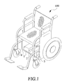
- Figure 1 is a perspective view showing an electrical wheelchair in which a power management system for controlling both primary and secondary power systems that selectively supply power to a motor of the electrical wheelchair in accordance with the present invention is embodied;
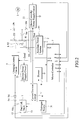
- FIG. 2 is a circuit block diagram of the power management system in accordance with the present invention.
- Figure 3 is a plot of charging current as a function of charging voltage when the primary power system charges the secondary power system under the control of the power management system of the present invention.
- FIG. 1 shows an electric wheelchair, generally designated with reference numeral 100 , in which a power management system constructed in accordance with the present invention is embodied
- the electrical wheelchair 100 is equipped with a fuel cell power system which comprises at least one fuel cell stack 1 , serving as a primary power system, and an auxiliary power system 2 , serving as a secondary power system, both selectively supplying power to an electric motor 3 that drives the wheelchair 100 .
- a fuel cell power system which comprises at least one fuel cell stack 1 , serving as a primary power system, and an auxiliary power system 2 , serving as a secondary power system, both selectively supplying power to an electric motor 3 that drives the wheelchair 100 .
- the power management system controls the power supplied from both the fuel cell stack 1 and the auxiliary power system 2 to the motor 3.
- the fuel cell stack 1 supplies an output voltage Vfc that is supplied to the motor 3 through diodes D1, D2.
- the motor 3 is parallel connected with a current division circuit 4, which will be further described.
- the fuel cell power system comprises a hydrogen source 11 , which supplies hydrogen to the fuel cell stack 1 for electro-chemical reaction inside the fuel cell stack 1 .
- An example of the hydrogen source is a hydrogen canister that contains substance capable of absorbing and preserving hydrogen.
- the fuel cell output voltage Vfc after flowing through the diodes D1, D2, is supplied to a charging control circuit 5, serving as a charging source for the auxiliary power system 2 .
- the charging power is supplied through a diode D3 to the auxiliary power system 2 for charging the later.
- the auxiliary power system 2 supplies an output voltage Vbat , such as 36V DC.
- Vbat is supplied through a diode D4 , a switch SW to a blower power supply circuit 21 , which in turn supplies an output voltage, such as 24V, as an operation voltage for a blower 6 .
- the auxiliary power system 2 comprises at least one rechargeable cell, such as lithium cell, nickel-hydride cell, and other secondary cells.
- a micro-controller power supply circuit 22 receives the output voltage of the blower power supply circuit 21 and in turn provides a micro-controller operation voltage, such as 12V DC, supplied to a micro-controller 7 .
- the micro-controller 7 controls the operation of the power management system of the present invention.
- An output of the auxiliary power system 2 is connected to a first voltage detection terminal PVbat , by which the micro-controller 7 detects and monitors the output voltage Vbat of the auxiliary power system 2 .
- a first temperature detector 23 detects the operation temperature of the cell of the auxiliary power system 2 and issues a temperature signal representing the operation temperature of the cell of the auxiliary power system 2 to a first temperature detection terminal PTbat of the micro-controller 7 .
- the micro-controller 7 comprises a charging current control terminal PIcmd, which is coupled to the charging control circuit 5.
- the charging current control terminal PIcmd issues a charging current control signal Icmd to the charging control circuit 5 for controlling the magnitude of the charging current supplied to the auxiliary power system 2 .
- the micro-controller 7 further has a second voltage detection terminal PVfc that is coupled to the output of the fuel cell stack 1 for detecting the output voltage Vfc of the fuel cell stack 1.
- a second temperature detector 12 detects operation temperature of the fuel cell stack 1 and issues a temperature signal representing the operation temperature of the fuel cell stack 1 to a second temperature detection terminal PTfc of the micro-controller 7 .
- a hydrogen pressure detector 13 detects the pressure of hydrogen supplied to the fuel cell stack 1 and issues a hydrogen pressure signal representing the hydrogen pressure to a hydrogen pressure detection terminal PH of the micro-controller 7 .
- a relay 8 including a coil 81 and a switching contact 82 , is connected between the auxiliary power system 2 and the motor 3 for controlling power supplied from the auxiliary power system 2 to the motor 3 .
- the coil 81 is coupled to and energized by a relay control terminal RLY of the micro-controller 7 , while the switching contact 82 that is connected to the motor 3 via a diode D5 is selectively engageable with the output of the auxiliary power system 2 under the control of the coil 81 .
- the output voltage Vbat is supplied through the diode D4 and the switch SW to the blower power supply circuit 21 , which in turn supplies an output voltage that is fed to the blower 6 as operation voltage to drive the blower 6 to supply air to the fuel cell stack 1 .
- the output voltage of the blower power supply circuit 21 is also fed to the micro-controller power supply circuit 22 and is down converted by the micro-controller power supply circuit 22 to a proper level, such as 12V DC, for operating the micro-controller 7 .
- the micro-controller 7 Upon receiving the operation voltage, the micro-controller 7 is initialized and performs a predetermined process to start up the fuel cell stack 1 . Hydrogen is then supplied to the fuel cell of the fuel cell stack 1 , which in turn generates and supplies electrical power to the motor 3 .
- micro-controller 7 detects the output voltage Vbat of the auxiliary power system 2 at an unloaded condition. If the output voltage Vbat of the auxiliary power system 2 is lower than a first predetermined value, such as 24V, the micro-controller 7 that issues the charging current control signal Icmd controls the charging control circuit 5 to supply the charging current to the auxiliary power system 2 .
- a first predetermined value such as 24V
- the micro-controller 7 energizes, via the relay control terminal RLY , the coil 81 of the relay 8 to allow the output voltage Vbat of the auxiliary power system 2 to apply to the motor 3 through the switching contact 82 of the relay 8 and the diode D5 .
- a second predetermined value such as 18V
- the relay 8 including the coil 8 and the switching contact 82 , constitutes a switching control circuit that switches between a first power supply condition where only electrical power from the fuel cell stack 1 is supplied to the motor 3 and a second power supply condition where electrical power from both the fuel cell stack 1 and the auxiliary power system 2 are simultaneously supplied to the motor 3 in a parallel manner.
- the second power supply condition is generally adapted to handle high load operation of the electric wheelchair 100
- the first power supply condition is adapted in small load operation.
- the switch SW When the switch SW is de-actuated, the power supplied from the auxiliary power system 2 to the blower power supply circuit 21 is cut off, which in turn stops supplying power to the blower 6 and the micro-controller 7 .
- the coil 81 of the relay 8 is de-energized and the switching contact 82 opens.
- the charging control circuit 5 is also shut down, terminating the charging current supplied therefrom. Under this circumstance, residual power generated by the fuel cell stack 1 is fed through the current division circuit 4 and consumed thereby.
- the current division circuit 4 may function to limit an upper bound of the output voltage of the fuel cell stack 1 to for example 36V for protecting the power management system from damage caused by exceedingly high voltage.
- the motor 3 when the electrical wheelchair 100 decelerates, the motor 3 operates like a generator, which supplies power in the reversed direction that may damage the power management system.
- the current division circuit 4 also functions to eliminate the reversed power and protect the system and the fuel cell from being damaged by the reversed power. All these facilitate protection of the fuel cell and power management system from damage caused by residual and/or undesired power.
- the current division circuit 4 may comprise a resistor or the like to consume the residual power.
- the charging control circuit 5 charges the auxiliary power system 2 .
- the output voltage Vbat of the auxiliary power system 2 is fed to the micro-controller 7 , which in turn issues the charging control signal Icmd.
- the output voltage Vbat of the auxiliary power system 2 determines the charging control signal Icmd.
- the charging control signal Icmd has a magnitude of "0".
- the charging control signal Icmd issued by the micro-controller 7 carries a zero ampere current.
- the charging control circuit 5 When the unloaded output voltage Vbat of the auxiliary power system 2 is lower than the predetermined level, such as 27V, the charging control circuit 5 generates a charging current to charge the auxiliary power system 2 .
- the charging current can be determined for example in proportion to the output voltage Vbat of the auxiliary power system 2 .
- FIG. 3 An example of setting the charging current that charges the auxiliary power system 2 is illustrated in Figure 3 .
- the charging control circuit 5 When the output voltage Vbat of the auxiliary power system 2 is between 18-29V, the charging control circuit 5 generates a charging current of 3A to charge the auxiliary power system 2. With the progress of the charging process, the output voltage Vbat of the auxiliary power system 2 increases. Once the output voltage Vbat reaches 29V, the micro-controller 7 decreases the charging control signal Icmd in a linear manner, which in turn linearly decreases the charging current from the charging control circuit 5 whereby when the output voltage Vbat reaches 30V, the charging current becomes 0A and charging to the auxiliary power system 2 is ceased.
- the auxiliary power system 2 In discharging, when the output voltage Vbat lowers to a predetermined level, such as 18V, which indicates that the rechargeable cell of the auxiliary power system 2 is completely discharged, for the sake of safety, the discharging of the auxiliary power system 2 is terminated. Further, when the operation temperature Tbat of the auxiliary power system 2 is equal to or higher than 60°C, which indicates an abnormal condition, the auxiliary power system 2 is shut down. When the hydrogen pressure detector 13 shows that the pressure of hydrogen supplied to the fuel cell stack 1 of the fuel cell power system is lower than 10 psig, which indicates the hydrogen source of the fuel cell stack 1 runs up, the hydrogen source is shut down.
- the charging control circuit 5 between the fuel cell stack 1 and the auxiliary power system 2 , power supply of different combination between two power systems can be realized, which allows for operation of the electrical device, such as the electrical wheelchair, in a more power efficient and better controlled manner. Maintaining the power level of the auxiliary power system 2 can also be realized in a simple and effective way by issuing a single charging control signal Icmd that controls the current charging the auxiliary power system 2 .
- the present invention adapts a dual cell power supply, which combines a rechargeable cell with a primary, fuel cell power system to provide an extra amount of power to handle peak power consumption.
- a rechargeable cell based auxiliary power system also serves to start up the whole power supply system, which is primarily operated with the fuel cell stack at nominal power consumption, which in the example of electrical wheelchair is around 200W, while the peak power consumption, which is averagely 400W, but can sometimes reach as high as 1,000W, is shared by both power systems.
Landscapes
- Engineering & Computer Science (AREA)
- Life Sciences & Earth Sciences (AREA)
- Sustainable Development (AREA)
- Sustainable Energy (AREA)
- Chemical & Material Sciences (AREA)
- Chemical Kinetics & Catalysis (AREA)
- Electrochemistry (AREA)
- General Chemical & Material Sciences (AREA)
- Manufacturing & Machinery (AREA)
- Transportation (AREA)
- Power Engineering (AREA)
- Mechanical Engineering (AREA)
- Health & Medical Sciences (AREA)
- Animal Behavior & Ethology (AREA)
- General Health & Medical Sciences (AREA)
- Public Health (AREA)
- Veterinary Medicine (AREA)
- Fuel Cell (AREA)
- Electric Propulsion And Braking For Vehicles (AREA)
- Charge And Discharge Circuits For Batteries Or The Like (AREA)
Applications Claiming Priority (3)
| Application Number | Priority Date | Filing Date | Title |
|---|---|---|---|
| TW092133655A TWI253196B (en) | 2003-12-01 | 2003-12-01 | Double cell electric energy manager of electrically driven equipment with fuel cell |
| CN203101172789 | 2003-12-10 | ||
| CN200310172789 | 2003-12-10 |
Publications (1)
| Publication Number | Publication Date |
|---|---|
| EP1542308A2 true EP1542308A2 (fr) | 2005-06-15 |
Family
ID=49261821
Family Applications (1)
| Application Number | Title | Priority Date | Filing Date |
|---|---|---|---|
| EP04029084A Withdrawn EP1542308A2 (fr) | 2003-12-01 | 2004-12-08 | Système de gestion d'énergie pour des véhicules électriques propulsés par un système hybride pile à combustible-batterie |
Country Status (5)
| Country | Link |
|---|---|
| US (1) | US20050118472A1 (fr) |
| EP (1) | EP1542308A2 (fr) |
| JP (1) | JP2005168279A (fr) |
| CA (1) | CA2488833A1 (fr) |
| TW (1) | TWI253196B (fr) |
Cited By (2)
| Publication number | Priority date | Publication date | Assignee | Title |
|---|---|---|---|---|
| US20110172843A1 (en) * | 2010-01-12 | 2011-07-14 | Inventec Appliances (Shanghai) Co. Ltd. | Electronic device and power management method thereof |
| CN105966261A (zh) * | 2016-07-01 | 2016-09-28 | 无锡雨德智能物联网科技有限公司 | 一种可更换电池供电的电动汽车供电系统 |
Families Citing this family (15)
| Publication number | Priority date | Publication date | Assignee | Title |
|---|---|---|---|---|
| JP4734939B2 (ja) * | 2005-01-28 | 2011-07-27 | 株式会社デンソー | 2次電池充電システム |
| JP4512536B2 (ja) * | 2005-08-09 | 2010-07-28 | 株式会社栗本鐵工所 | 燃料電池搭載電動車イスの燃料ボンベ設置構造 |
| JP4380676B2 (ja) * | 2006-09-12 | 2009-12-09 | トヨタ自動車株式会社 | 移動体 |
| EP2454779B1 (fr) * | 2009-05-22 | 2020-01-15 | Battelle Memorial Institute | Procédé de commande de système de convertisseur de combustible et de piles à combustible intégré |
| KR101146378B1 (ko) * | 2010-06-09 | 2012-05-17 | 삼성에스디아이 주식회사 | 배터리 팩 및 배터리팩의 충전 시스템 |
| US8450965B2 (en) * | 2010-07-20 | 2013-05-28 | GM Global Technology Operations LLC | Stack-powered fuel cell monitoring device with prioritized arbitration |
| KR101418180B1 (ko) * | 2012-12-20 | 2014-07-14 | 현대오트론 주식회사 | 연료전지 스택 고장 진단 방법 |
| CN104323890A (zh) * | 2013-03-06 | 2015-02-04 | 赵彦杰 | 电热轮椅 |
| JP6164199B2 (ja) * | 2014-11-15 | 2017-07-19 | トヨタ自動車株式会社 | 電源システムおよび燃料電池の電圧制御方法 |
| WO2017031752A1 (fr) * | 2015-08-27 | 2017-03-02 | Intel Corporation | Commande de puissance de crête et séquencement pour alimentations électriques multiples |
| CN107128184B (zh) * | 2016-02-26 | 2020-12-25 | 上海恒劲动力科技有限公司 | 燃料电池与储能电池混合动力车控制方法及车系统 |
| CN109245500A (zh) * | 2017-07-10 | 2019-01-18 | 中兴通讯股份有限公司 | 供电方法、装置及系统 |
| CN108819767B (zh) * | 2018-06-29 | 2020-06-09 | 奇瑞汽车股份有限公司 | 氢燃料电池汽车动力系统的控制方法及装置 |
| CN110182105A (zh) * | 2018-10-18 | 2019-08-30 | 丰疆智能科技研究院(常州)有限公司 | 拖拉机及其供能管理系统和应用 |
| CN112339580B (zh) * | 2020-11-09 | 2022-03-25 | 东风汽车集团有限公司 | 一种燃料电池汽车能量管理优化方法和系统 |
Family Cites Families (5)
| Publication number | Priority date | Publication date | Assignee | Title |
|---|---|---|---|---|
| JP4218202B2 (ja) * | 2000-10-04 | 2009-02-04 | トヨタ自動車株式会社 | 燃料電池を有する直流電源 |
| US6580977B2 (en) * | 2001-01-16 | 2003-06-17 | Ford Global Technologies, Llc | High efficiency fuel cell and battery for a hybrid powertrain |
| US6559621B2 (en) * | 2001-05-21 | 2003-05-06 | Cellex Power Products, Inc. | Hybrid energy storage device charge equalization system and method |
| US20020175007A1 (en) * | 2001-05-25 | 2002-11-28 | Strong Russell W. | Modular mobility vehicle |
| US7144646B2 (en) * | 2001-12-14 | 2006-12-05 | Ballard Power Systems Inc. | Method and apparatus for multiple mode control of voltage from a fuel cell system |
-
2003
- 2003-12-01 TW TW092133655A patent/TWI253196B/zh not_active IP Right Cessation
-
2004
- 2004-09-17 JP JP2004271693A patent/JP2005168279A/ja active Pending
- 2004-11-29 CA CA002488833A patent/CA2488833A1/fr not_active Abandoned
- 2004-11-30 US US10/998,730 patent/US20050118472A1/en not_active Abandoned
- 2004-12-08 EP EP04029084A patent/EP1542308A2/fr not_active Withdrawn
Cited By (3)
| Publication number | Priority date | Publication date | Assignee | Title |
|---|---|---|---|---|
| US20110172843A1 (en) * | 2010-01-12 | 2011-07-14 | Inventec Appliances (Shanghai) Co. Ltd. | Electronic device and power management method thereof |
| US8428787B2 (en) * | 2010-01-12 | 2013-04-23 | Inventec Appliances (Shanghai) Co., Ltd. | Electronic device and power management method thereof |
| CN105966261A (zh) * | 2016-07-01 | 2016-09-28 | 无锡雨德智能物联网科技有限公司 | 一种可更换电池供电的电动汽车供电系统 |
Also Published As
| Publication number | Publication date |
|---|---|
| CA2488833A1 (fr) | 2005-06-01 |
| JP2005168279A (ja) | 2005-06-23 |
| TW200520282A (en) | 2005-06-16 |
| US20050118472A1 (en) | 2005-06-02 |
| TWI253196B (en) | 2006-04-11 |
Similar Documents
| Publication | Publication Date | Title |
|---|---|---|
| EP1542308A2 (fr) | Système de gestion d'énergie pour des véhicules électriques propulsés par un système hybride pile à combustible-batterie | |
| JP4367251B2 (ja) | 電源装置及び電子機器 | |
| US9371005B2 (en) | Battery management apparatus for an electric vehicle, and method for managing same | |
| JP3615445B2 (ja) | ハイブリッドカーの電源装置 | |
| CN102113192B (zh) | 多功能便携式储存及供应系统 | |
| WO2002035625A3 (fr) | Appareil equipe d'un bloc d'alimentation avec accumulateur de piles a combustible metal-air rechargeable pouvant etre ravitaille en carburant | |
| US20130127418A1 (en) | Electric vehicle and charging control method for battery thereof | |
| WO2002035627A3 (fr) | Unite d'alimentation electrique a pile a combustible metal-air rechargeable et a capacite de ravitaillement en combustible destinee a etre integree dans un appareil | |
| US8445153B2 (en) | Fuel cell high-potential prevention control system | |
| EP3670238B1 (fr) | Système d'alimentation électrique et son procédé de fonctionnement | |
| WO2010112998A1 (fr) | Système de pile à combustible, procédé de commande de ce système et véhicule équipé dudit système | |
| JP4488381B2 (ja) | 電池パックシステム | |
| US6765317B2 (en) | Power supply module for electrical power tools | |
| KR102556389B1 (ko) | 초소형 전기차용 보조 배터리 시스템, 초소형 전기차용 보조 배터리를 충전하는 장치 및 방법 | |
| WO2004010522A2 (fr) | Procede et dispositif pour la protection d'une pile a combustible | |
| WO2012096199A2 (fr) | Dispositif d'alimentation électrique, dispositif onduleur, outil électrique | |
| CN107248771A (zh) | 新能源供电的蓄电池保护系统及其方法 | |
| KR20160122005A (ko) | 차량 전원 관리 장치 | |
| WO2010113000A1 (fr) | Système de pile à combustible et véhicule et équipé de ce système de pile à combustible | |
| JP4168581B2 (ja) | 高電圧電池の負荷起動装置 | |
| JP3526277B2 (ja) | 組電池の放電方法及び組電池の放電回路 | |
| KR101712123B1 (ko) | 하이브리드 비상 발전 장치 및 방법 | |
| JP3419122B2 (ja) | 組電池の保護装置 | |
| JP4560833B2 (ja) | 電力バックアップ装置 | |
| KR20180051804A (ko) | 에너지 저장 장치 |
Legal Events
| Date | Code | Title | Description |
|---|---|---|---|
| PUAI | Public reference made under article 153(3) epc to a published international application that has entered the european phase |
Free format text: ORIGINAL CODE: 0009012 |
|
| AK | Designated contracting states |
Kind code of ref document: A2 Designated state(s): AT BE BG CH CY CZ DE DK EE ES FI FR GB GR HU IE IS IT LI LT LU MC NL PL PT RO SE SI SK TR |
|
| AX | Request for extension of the european patent |
Extension state: AL BA HR LV MK YU |
|
| STAA | Information on the status of an ep patent application or granted ep patent |
Free format text: STATUS: THE APPLICATION HAS BEEN WITHDRAWN |
|
| 18W | Application withdrawn |
Effective date: 20071107 |