EP1542359B1 - Gerät zur Dynamikbegrenzung/-dehnung und mobiles Kommunikationsgerät - Google Patents
Gerät zur Dynamikbegrenzung/-dehnung und mobiles Kommunikationsgerät Download PDFInfo
- Publication number
- EP1542359B1 EP1542359B1 EP04028604A EP04028604A EP1542359B1 EP 1542359 B1 EP1542359 B1 EP 1542359B1 EP 04028604 A EP04028604 A EP 04028604A EP 04028604 A EP04028604 A EP 04028604A EP 1542359 B1 EP1542359 B1 EP 1542359B1
- Authority
- EP
- European Patent Office
- Prior art keywords
- signal
- level
- circuit
- compression
- frequency band
- Prior art date
- Legal status (The legal status is an assumption and is not a legal conclusion. Google has not performed a legal analysis and makes no representation as to the accuracy of the status listed.)
- Expired - Lifetime
Links
- 230000006835 compression Effects 0.000 title claims description 54
- 238000007906 compression Methods 0.000 title claims description 54
- 238000010295 mobile communication Methods 0.000 title claims description 8
- 230000003321 amplification Effects 0.000 claims description 32
- 238000003199 nucleic acid amplification method Methods 0.000 claims description 32
- 238000001514 detection method Methods 0.000 claims description 14
- 230000015572 biosynthetic process Effects 0.000 claims description 5
- 238000003786 synthesis reaction Methods 0.000 claims description 5
- 230000001413 cellular effect Effects 0.000 description 4
- 238000010586 diagram Methods 0.000 description 4
- 230000007423 decrease Effects 0.000 description 3
- 230000003247 decreasing effect Effects 0.000 description 1
- 230000007812 deficiency Effects 0.000 description 1
- 238000005516 engineering process Methods 0.000 description 1
- 238000012986 modification Methods 0.000 description 1
- 230000004048 modification Effects 0.000 description 1
- 230000005236 sound signal Effects 0.000 description 1
Images


Classifications
-
- H—ELECTRICITY
- H03—ELECTRONIC CIRCUITRY
- H03G—CONTROL OF AMPLIFICATION
- H03G9/00—Combinations of two or more types of control, e.g. gain control and tone control
- H03G9/005—Combinations of two or more types of control, e.g. gain control and tone control of digital or coded signals
-
- H—ELECTRICITY
- H03—ELECTRONIC CIRCUITRY
- H03G—CONTROL OF AMPLIFICATION
- H03G9/00—Combinations of two or more types of control, e.g. gain control and tone control
- H03G9/02—Combinations of two or more types of control, e.g. gain control and tone control in untuned amplifiers
- H03G9/025—Combinations of two or more types of control, e.g. gain control and tone control in untuned amplifiers frequency-dependent volume compression or expansion, e.g. multiple-band systems
-
- H—ELECTRICITY
- H03—ELECTRONIC CIRCUITRY
- H03G—CONTROL OF AMPLIFICATION
- H03G9/00—Combinations of two or more types of control, e.g. gain control and tone control
- H03G9/02—Combinations of two or more types of control, e.g. gain control and tone control in untuned amplifiers
- H03G9/12—Combinations of two or more types of control, e.g. gain control and tone control in untuned amplifiers having semiconductor devices
- H03G9/18—Combinations of two or more types of control, e.g. gain control and tone control in untuned amplifiers having semiconductor devices for tone control and volume expansion or compression
Definitions
- the present invention relates to a signal compression/expansion device, and more particularly to a signal compression/expansion device which controls an input signal with a gain in accordance with its level and a mobile communication terminal to which the signal compression/expansion device is applied.
- a dynamic range is important.
- a signal having large amplitude is inputted to the amplifier and the speaker, a waveform of the outputted signal is significantly distorted.
- an automatic gain controller AGC
- the automatic gain controller when a signal reaches a predetermined level, a gain of an amplifier is decreased. As a result, an effective dynamic range of the amplifier is made wider.
- the "dynamic range” means a ratio of a level at which a signal/noise ratio (S/N ratio) has a predetermined value to a maximum level at which a signal saturates.
- a speaker built in a mobile communication terminal such as a cellular phone has an extremely smaller size than a speaker of a general an audio system, and its dynamic range and frequency characteristic are poor.
- a dynamic range of an amplifier for a speaker is narrow because of a limitation to a power supply. Accordingly, in a speaker built in a cellular phone, loud sound is distorted, and a low frequency area of the sound lacks sound pressure. Thus, a frequency characteristic has a peak in a high frequency range. Therefore, the automatic gain controller effectively widens a dynamic range.
- an automatic gain control that is, compression processing
- a uniform dynamic range is formed.
- Japanese Patent Laid-Open No. 2001-308730 discloses a digital receiver capable of widening a dynamic range of an A/D converter over a wide frequency band.
- a receiving signal over a wide band is divided by N band-pass filters.
- an automatic gain control amplifier amplifies the receiving signal so that the maximum signal level of an output of each band-pass filter becomes equal to 1/N of the maximum input level of the A/D converter, and adds the amplified receiving signals.
- signals having a very high level, which are included in the receiving signals are suppressed, and signals having a very low level, which are included therein, are amplified.
- the digital receiver adjusts an amplification rate for each band of the input signal based on a signal level for each band, and forms a dynamic range.
- the digital receiver adjusts an amplification rate for each band of the input signal based on a signal level for each band, and forms a dynamic range.
- US-A-4 882 762 discloses a signal compression/expansion device comprising a frequency band division circuit, a compression/expansion circuit and a frequency band synthesis circuit for adding signals outputted from the respective compression/expansion circuit, wherein at least one compression/expansion circuit applies a different gain for the input signal in accordance with a level of the input signal.
- a frequency band division circuit 10 receives a signal through an input terminal 40, and divides the signal into N frequency bands. Then, the frequency band division circuit 10 outputs signals 41, 42, 43, Vietnamese, and 4N corresponding to the respective frequency bands.
- a compression/expansion circuits 21, 22, 23,...., and 2N respectively receive the signals 41, 42, 43, Vietnamese, and 4N.
- the respective compression/expansion circuits adjust levels of the input signals in accordance with their levels, and output the signals.
- the compression/expansion circuits are capable of possessing intrinsic I/O characteristics respectively, and output the signals after compressing/expanding levels of the input signals based on the respective I/O characteristics.
- the compression can mean that the input signal is output in a state where its level is suppressed.
- the expansion can mean that the input signal is output in a state where its level is elevated.
- a frequency band synthesis circuit 30 adds the signals 51, 52, 53,....and 5N, which are outputted from the respective compression/expansion circuits 21, 22, 23, Vietnamese, and 2N, and outputs an addition result to an output terminal 50.
- the output terminal 50 is connected to a speaker or an amplifier for driving the speaker, which are not illustrated in FIG. 1 .
- a gain applied to an input signal smaller than a predetermined level differs from that applied to another input signal higher than the predetermined level.
- a compression/expansion circuit which compresses/expands the input signal with a constant gain can be also arranged.
- a "level” does not mean an instantaneous value of a signal but means an effective value or a value equivalent to a short-time average such as a power or an envelope signal.
- the compression/expansion circuit variously compresses/expands levels of signals in respective frequency bands in accordance with a dynamic range of a speaker or an amplifier for driving the speaker. As a result, occurrence of distortion of an acoustic signal outputted from the speaker is suppressed.
- FIG. 2 is a graph illustrating an example of a frequency characteristic of the frequency band division circuit 10.
- the circuit 10 divides the input signal to N bands including the frequency bands F1, F2, Vietnamese, a wide range of frequencies, and a wide range of frequencies, and a wide range of frequencies, and frequencies.
- the circuit 10 has N band pass filters, for example.
- FIG.3A and FIG.3B show examples of the compression/expansion circuit.
- the compression/expansion circuit has a variable amplification circuit 60 and a level detection circuit 61.
- the compression/expansion circuit has a feed-forward type of configuration.
- a signal 4K is inputted to the variable amplification circuit 60 and the level detection circuit 61.
- the level detection circuit 61 monitors a signal level of the input signal 4K, and compares the signal level with a predetermined threshold value. Thereafter, the level detection circuit 61 outputs a comparison result to the variable amplification circuit 60.
- the variable amplification circuit 60 changes its amplification rate (that is, gain) in accordance with the signal received from the level detection circuit 61.
- the variable amplification circuit 60 outputs a signal 5K to the frequency synthesis circuit 30.
- the compression/expansion circuit has a feedback type of configuration.
- the input signal 4K is inputted to the variable amplification circuit 60.
- the level detection circuit 61 monitors a signal level of the signal 5K outputted from the variable amplification circuit 60, and outputs a monitor result to the variable amplification circuit 60.
- the variable amplification circuit 60 changes its amplification rate (that is, gain) in accordance with the monitor result which is outputted from the level detection circuit 61.
- the level detection circuit 61 is capable of comparing the level of the output signal of the variable amplification circuit 60 with a predetermined threshold value, and of outputting a comparison result to the variable amplification circuit. Alternatively, the level detection circuit 61 is capable of outputting the detected level of the output signal of the variable amplification circuit 60 to the variable amplification circuit 60.
- FIG. 4A when a level of an input signal exceeds a threshold value th0, an amplification rate (i.e. gain) decreases. When the level of the input signal exceeds the threshold value th0, the level of the input signal can be compressed. In FIG. 4B , the amplification rate does not change, and a level of an output signal changes linearly with respect to the level of the input signal. There is a chance that the input signal may not be compressed/expanded. In FIG. 4C , when the level of the input signal exceeds the threshold value th1, the amplification rate increases.
- the amplification rate decreases.
- the level of the input signal exceeds a threshold value th2 or less, there is a chance that the level of the input signal may be expanded.
- the level of the input signal exceeds the threshold value th2, there is a chance that the level of the input signal may be compressed.
- the compression/expansion circuit can have a plurality of threshold values.
- FIG. 5 shows an example of a mobile communication terminal loading the foregoing signal compression/expansion device.
- the mobile communication terminal 5 comprises a sound source circuit 2, a signal compression/expansion device 1, an amplification circuit 3 and a speaker 4.
- the sound source circuit 2 generates a sound source signal such as incoming call sound (e.g. incoming call melody).
- An output signal from the sound source circuit 2 is inputted to the signal compression/expansion device 1, and compressed/expanded depending on respective frequency bands.
- the amplification circuit 3 amplifies the signal compressed/expanded to drive the speaker 4. Note that if the level of the output signal of the signal compression/expansion device 1 is high enough to drive the speaker 4, the amplification circuit 3 needs not to be provided.
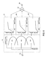
- FIG. 6 shows another example of the signal compression/expansion device of the present invention.
- the frequency band division circuit 10 divides the input signal into three frequency bands.
- the compression/expansion circuit 21 corresponding to the low frequency band F1 has an I/O characteristic shown in FIG. 4D .
- This compression/expansion circuit 21 expands the input signal with a high amplification rate in order to compensate sound pressure of the speaker at a low frequency band. Another reason why this operation is performed is because it is difficult for a human to listen to a low frequency signal of a small sound volume.
- the compression/expansion circuit 22 corresponding to the intermediate frequency band F2 has an I/O characteristic shown in FIG. 4A .
- a threshold value th4 is set to a region of a large input level (that is, th4>th3). Since distortion occurs in a region where a level of the input signal is high, a compression characteristic is desirable.
- the compression/expansion circuit 23 corresponding to the high frequency band F3 has an I/O characteristic shown in FIG. 4A .
- a threshold value th5 is set to a region of a low input level. When the level of the input signal becomes high, sound in a high frequency is emphasized. To prevent this phenomenon, the compression characteristic is preferable.
- an amplification rate of the compression/expansion circuit can be set to a low value so that the output level equal to the threshold value th5 or less is made to be low.
- the signal compression/expansion device can be configured as a device for processing an analog signal. Furthermore, the signal compression/expansion device can be realized by a digital signal processing device.
- the frequency band division circuit 10 is realized by a Fourier transform circuit
- the band synthesis circuit 30 is realized by an inverse Fourier transform circuit.
Landscapes
- Tone Control, Compression And Expansion, Limiting Amplitude (AREA)
- Circuit For Audible Band Transducer (AREA)
Claims (4)
- Vorrichtung zur Signalkompression/-expansion für ein mobiles Kommunikationsgerät, mit:einer Frequenzbandteilungsschaltung (10) zum Teilen eines Eingangssignals in drei Frequenzbänder, nämlich ein Niederfrequenzband (F1), ein Zwischenfrequenzband (F2) und ein Hochfrequenzband (F3);Kompressions-/Expansionsschaltungen (21, 23) zum Empfangen des Eingangssignals eines vorbestimmten Frequenzbandes und zum Steuern eines Pegels des Eingangssignals auf der Grundlage eines vorbestimmten Verstärkungsfaktors; undeiner Frequenzbandsyntheseschaltung (30) zum Addieren von Signalen (51-53), die von den entsprechenden Kompressions-/Expansionsschaltungen (21-23) ausgegeben worden sind,dadurch gekennzeichnet, dass die Schaltung (21) das Niederfrequenzbandsignal (F1) mit einer hohen Verstärkungsrate expandiert, wenn der Pegel des Niederfrequenzsignals niedriger als ein erster Pegel (th3) ist,die Schaltung (22) das Zwischenfrequenzband (F2) komprimiert, wenn der Pegel des Zwischenfrequenzbandsignals höher als ein zweiter Pegel (th4) ist, der höher als der erste Pegel (th3) ist, unddie Schaltung (23) das Hochfrequenzsignal (F3) komprimiert, wenn der Pegel des Hochfrequenzbandsignals (F3) höher als ein dritter Pegel (th5) ist, der niedriger als der zweite Pegel (th4) ist.
- Vorrichtung zur Signalkompression/-expansion nach Anspruch 1,
wobei wenigstens eine Kompressions-/Expansionsschaltung (21-2N) eine variable Verstärkungsschaltung (60) und eine Pegeldetektionsschaltung (61) aufweist,
die Pegeldetektionsschaltung von der Frequenzbandteilungsschaltung (10) ausgegebene Signal empfängt und das empfangende Signal mit einem vorbestimmten Pegel vergleicht, somit ein Vergleichsergebnis an die variable Verstärkungsschaltung (60) ausgibt, und
die variable Verstärkungsschaltung (60) ein von der Frequenzbandteilungsschaltung (10) ausgegebenes Signal empfängt und den Pegel des Signals mit einem vorbestimmten Verstärkungsfaktor in Übereinstimmung mit dem Vergleichsergebnis steuert, somit das Signal ausgibt. - Vorrichtung zur Signalkompression/-expansion nach Anspruch 1,
wobei wenigstens eine Kompressions-/Expansionsschaltung eine variable Verstärkungsschaltung (60) und eine Pegeldetektionsschaltung (61) aufweist,
die variable Verstärkungsschaltung (60) ein von der Frequenzbandteilungsschaltung (10) ausgegebenes Signal empfängt und den Pegel des empfangenen Signals mit einem vorbestimmten Verstärkungsfaktor basierend auf einem von der Pegeldetektionsschaltung (61) empfangenen Signals steuert, somit das Signal ausgibt, und
die Pegeldetektionsschaltung (61) ein von der Kompressions-/Expansionsschaltung (21-2N) ausgegebenes Signal empfängt und ein vorbestimmtes Signal an die variable Verstärkungsschaltung (60) in Übereinstimmung mit dem empfangenen Signalpegel ausgibt. - Mobiles Kommunikationsgerät mit:einer Schallquellenschaltung;einer Signalkompressions-/-expansionsvorrichtung gemäß Anspruch 1zum Steuern eines Pegels eines von dem Schallquellensignal ausgegebenen Signals basierend auf einem vorbestimmten Verstärkungsfaktor; undeinem Lautsprecher zum Umwandeln eines von der Signalkompressions-/ -expansionsvorrichtung ausgegebenen Signals in einen Schall.
Applications Claiming Priority (2)
| Application Number | Priority Date | Filing Date | Title |
|---|---|---|---|
| JP2003410212 | 2003-12-09 | ||
| JP2003410212A JP2005175674A (ja) | 2003-12-09 | 2003-12-09 | 信号圧縮伸張装置および携帯通信端末装置 |
Publications (2)
| Publication Number | Publication Date |
|---|---|
| EP1542359A1 EP1542359A1 (de) | 2005-06-15 |
| EP1542359B1 true EP1542359B1 (de) | 2009-07-29 |
Family
ID=34510493
Family Applications (1)
| Application Number | Title | Priority Date | Filing Date |
|---|---|---|---|
| EP04028604A Expired - Lifetime EP1542359B1 (de) | 2003-12-09 | 2004-12-02 | Gerät zur Dynamikbegrenzung/-dehnung und mobiles Kommunikationsgerät |
Country Status (5)
| Country | Link |
|---|---|
| US (1) | US20050123153A1 (de) |
| EP (1) | EP1542359B1 (de) |
| JP (1) | JP2005175674A (de) |
| CN (1) | CN1627635B (de) |
| DE (1) | DE602004022241D1 (de) |
Families Citing this family (32)
| Publication number | Priority date | Publication date | Assignee | Title |
|---|---|---|---|---|
| US7787640B2 (en) * | 2003-04-24 | 2010-08-31 | Massachusetts Institute Of Technology | System and method for spectral enhancement employing compression and expansion |
| WO2007072280A1 (en) * | 2005-12-22 | 2007-06-28 | Koninklijke Philips Electronics N.V. | A device for and a method of processing audio data |
| JP4804152B2 (ja) * | 2006-01-13 | 2011-11-02 | 富士通テン株式会社 | 音声信号調整装置、オーディオシステム、車載オーディオシステム |
| JP4472671B2 (ja) * | 2006-07-27 | 2010-06-02 | Necインフロンティア株式会社 | 電話機の送話歪防止装置 |
| JP4859928B2 (ja) * | 2006-10-03 | 2012-01-25 | ティーオーエー株式会社 | 放送装置 |
| WO2008126496A1 (ja) * | 2007-03-20 | 2008-10-23 | Nec Corporation | 電子機器用音響処理システム、方法及び携帯電話端末 |
| US7742746B2 (en) * | 2007-04-30 | 2010-06-22 | Qualcomm Incorporated | Automatic volume and dynamic range adjustment for mobile audio devices |
| JP4580409B2 (ja) * | 2007-06-11 | 2010-11-10 | 富士通株式会社 | 音量制御装置および方法 |
| EP2009786B1 (de) | 2007-06-25 | 2015-02-25 | Harman Becker Automotive Systems GmbH | Rückgekoppelter Begrenzer mit adaptiver Zeitkonstantensteuerung |
| US20090060209A1 (en) * | 2007-08-31 | 2009-03-05 | Victor Company Of Japan, Ltd. A Corporation Of Japan | Audio-signal processing apparatus and method |
| JP5062055B2 (ja) * | 2007-08-31 | 2012-10-31 | 株式会社Jvcケンウッド | 音声信号処理装置及び方法 |
| WO2009110087A1 (ja) * | 2008-03-07 | 2009-09-11 | ティーオーエー株式会社 | 信号処理装置 |
| US8934643B2 (en) | 2008-04-09 | 2015-01-13 | Koninklijke Philips N.V. | Generation of a drive signal for sound transducer |
| JP5115818B2 (ja) * | 2008-10-10 | 2013-01-09 | 国立大学法人九州大学 | 音声信号強調装置 |
| JP5136378B2 (ja) * | 2008-12-09 | 2013-02-06 | 富士通株式会社 | 音響処理方法 |
| US8626516B2 (en) * | 2009-02-09 | 2014-01-07 | Broadcom Corporation | Method and system for dynamic range control in an audio processing system |
| JP2010244602A (ja) * | 2009-04-03 | 2010-10-28 | Sony Corp | 信号処理装置及び方法、並びにプログラム |
| US9299362B2 (en) * | 2009-06-29 | 2016-03-29 | Mitsubishi Electric Corporation | Audio signal processing device |
| CN104242853B (zh) * | 2010-03-18 | 2017-05-17 | 杜比实验室特许公司 | 用于具有音质保护的失真减少多频带压缩器的技术 |
| US9130527B2 (en) | 2010-08-18 | 2015-09-08 | Dolby Laboratories Licensing Corporation | Method and system for controlling distortion in a critical frequency band of an audio signal |
| US8855322B2 (en) * | 2011-01-12 | 2014-10-07 | Qualcomm Incorporated | Loudness maximization with constrained loudspeaker excursion |
| JP2012169828A (ja) * | 2011-02-14 | 2012-09-06 | Sony Corp | 音声信号出力装置、スピーカ装置、音声信号出力方法 |
| WO2013038451A1 (ja) * | 2011-09-15 | 2013-03-21 | 三菱電機株式会社 | ダイナミックレンジ制御装置 |
| DE102012204193B4 (de) * | 2012-03-16 | 2015-10-22 | Algorithmix GmbH Digital Signal Processing Technologies | Audioprozessor und Verfahren zum Verstärken oder Dämpfen eines empfangenen Audiosignals |
| US9385674B2 (en) * | 2012-10-31 | 2016-07-05 | Maxim Integrated Products, Inc. | Dynamic speaker management for multichannel audio systems |
| EP2992605B1 (de) * | 2013-04-29 | 2017-06-07 | Dolby Laboratories Licensing Corporation | Frequenzbandkompression mit dynamischen schwellen |
| JP6244652B2 (ja) * | 2013-05-02 | 2017-12-13 | ヤマハ株式会社 | 音声処理装置及びプログラム |
| JP2015050685A (ja) * | 2013-09-03 | 2015-03-16 | ソニー株式会社 | オーディオ信号処理装置および方法、並びにプログラム |
| JP6085541B2 (ja) * | 2013-09-13 | 2017-02-22 | エムケー電子株式会社 | イヤースピーカ装置 |
| EP3089364B1 (de) | 2015-05-01 | 2019-01-16 | Nxp B.V. | Verstärkungsfunktionssteuerung |
| EP3171614B1 (de) | 2015-11-23 | 2020-11-04 | Goodix Technology (HK) Company Limited | Steuerung für ein audiosystem |
| CN119865737B (zh) * | 2025-03-25 | 2025-07-15 | 东莞市漫步者科技有限公司 | 信号处理方法、装置、电子设备以及存储介质 |
Family Cites Families (25)
| Publication number | Priority date | Publication date | Assignee | Title |
|---|---|---|---|---|
| GB1253031A (de) * | 1968-01-10 | 1971-11-10 | ||
| JPS53126845A (en) * | 1977-04-12 | 1978-11-06 | Saito Yoshiaki | Method of compressing and amplifying audio signal |
| JPS57164057A (en) * | 1981-03-31 | 1982-10-08 | Matsushita Electric Industrial Co Ltd | Hearing aid apparatus |
| JPS58194598A (ja) * | 1982-05-10 | 1983-11-12 | 小国 晃 | 螺旋鉛筆削り器 |
| US4467287A (en) * | 1982-06-04 | 1984-08-21 | Dbx, Inc. | Signal expander |
| US4882762A (en) * | 1988-02-23 | 1989-11-21 | Resound Corporation | Multi-band programmable compression system |
| JPH03187610A (ja) * | 1989-12-18 | 1991-08-15 | Kenwood Corp | 音響補正装置 |
| JPH0564297A (ja) * | 1991-09-05 | 1993-03-12 | Terumo Corp | 補聴器 |
| JPH05300595A (ja) * | 1992-04-21 | 1993-11-12 | Terumo Corp | 補聴器 |
| FI97758C (fi) * | 1992-11-20 | 1997-02-10 | Nokia Deutschland Gmbh | Järjestelmä audiosignaalin käsittelemiseksi |
| JPH07162998A (ja) * | 1993-12-03 | 1995-06-23 | Fujitsu Ten Ltd | 車載用音響装置 |
| JP3418808B2 (ja) * | 1995-02-27 | 2003-06-23 | 富士通株式会社 | 移動通信用端末機 |
| JPH0968997A (ja) * | 1995-08-30 | 1997-03-11 | Sony Corp | 音声処理方法及び装置 |
| US5832097A (en) * | 1995-09-19 | 1998-11-03 | Gennum Corporation | Multi-channel synchronous companding system |
| JP3373103B2 (ja) * | 1996-02-27 | 2003-02-04 | アルパイン株式会社 | オーディオ信号処理装置 |
| JPH09331223A (ja) * | 1996-06-12 | 1997-12-22 | Alpine Electron Inc | 信号処理装置 |
| JP3925572B2 (ja) * | 1997-06-23 | 2007-06-06 | ソニー株式会社 | 音声信号の処理回路 |
| JPH11261356A (ja) * | 1998-03-09 | 1999-09-24 | Matsushita Electric Ind Co Ltd | 音響再生装置 |
| JP2000022473A (ja) * | 1998-07-07 | 2000-01-21 | Sony Corp | 音声処理装置 |
| JP4170458B2 (ja) * | 1998-08-27 | 2008-10-22 | ローランド株式会社 | 波形信号の時間軸圧縮伸長装置 |
| JP4214607B2 (ja) * | 1999-03-23 | 2009-01-28 | ソニー株式会社 | マイクロホン装置 |
| EP1210765B1 (de) * | 1999-07-28 | 2007-03-07 | Clear Audio Ltd. | Verstärkungsregelung von audiosignalen in lärmender umgebung mit hilfe einer filterbank |
| JP2001230647A (ja) * | 2000-02-17 | 2001-08-24 | Oki Electric Ind Co Ltd | エキスパンダ回路 |
| JP2001237661A (ja) * | 2000-02-22 | 2001-08-31 | Oki Electric Ind Co Ltd | コンプレッサ回路 |
| JP4185984B2 (ja) * | 2003-11-04 | 2008-11-26 | 国立大学法人山梨大学 | 音信号の加工装置および加工方法 |
-
2003
- 2003-12-09 JP JP2003410212A patent/JP2005175674A/ja active Pending
-
2004
- 2004-12-01 US US11/000,455 patent/US20050123153A1/en not_active Abandoned
- 2004-12-02 DE DE602004022241T patent/DE602004022241D1/de not_active Expired - Lifetime
- 2004-12-02 EP EP04028604A patent/EP1542359B1/de not_active Expired - Lifetime
- 2004-12-07 CN CN200410096988.2A patent/CN1627635B/zh not_active Expired - Fee Related
Also Published As
| Publication number | Publication date |
|---|---|
| US20050123153A1 (en) | 2005-06-09 |
| JP2005175674A (ja) | 2005-06-30 |
| DE602004022241D1 (de) | 2009-09-10 |
| EP1542359A1 (de) | 2005-06-15 |
| CN1627635B (zh) | 2011-06-15 |
| CN1627635A (zh) | 2005-06-15 |
Similar Documents
| Publication | Publication Date | Title |
|---|---|---|
| EP1542359B1 (de) | Gerät zur Dynamikbegrenzung/-dehnung und mobiles Kommunikationsgerät | |
| US5396562A (en) | Signal processing circuit for audio apparatus | |
| US8600076B2 (en) | Multiband DRC system and method for controlling the same | |
| JP4787255B2 (ja) | 高雑音環境における提示のためのオーディオ信号処理システム及び方法 | |
| US7042986B1 (en) | DSP-enabled amplified telephone with digital audio processing | |
| US20090054109A1 (en) | Polyphonic ringtone annunciator with spectrum modification | |
| JPH01500788A (ja) | レイリーフェーデッド受信信号に対する応答を改善したfm受信機 | |
| WO2009029782A1 (en) | Variable automatic limit control (alc) threshold for any desired compression curve | |
| US20030007657A1 (en) | Hearing aid with sudden sound alert | |
| JPWO2007119362A1 (ja) | オーディオ回路 | |
| US9473102B2 (en) | Level adjusting circuit, digital sound processor, audio AMP integrated circuit, electronic apparatus and method of automatically adjusting level of audio signal | |
| US6317613B1 (en) | Audio in a mobile receiver | |
| CN115987236B (zh) | 一种音频信号处理系统及音频动态范围控制方法 | |
| US10483931B2 (en) | Audio device, speaker device, and audio signal processing method | |
| JP3925572B2 (ja) | 音声信号の処理回路 | |
| CN1988737A (zh) | 用于控制助听器的传递函数的系统 | |
| EP1217732B1 (de) | Drahtloses Mikrophon mit einem Mehrband - Audiokompandersystem für hohe Rauschreduktion und hohe Tonqualität | |
| CN108650363A (zh) | 一种手机音量调节方法及装置 | |
| EP0717888A1 (de) | Verstärker mit variabler verstärkung | |
| KR20040052236A (ko) | 베이스 주파수 증폭 장치 | |
| EP4521638A1 (de) | System und verfahren für mehrbandbegrenzer mit mehrfachfrequenzbereich | |
| US11689169B1 (en) | Linking audio amplification gain reduction per channel and across frequency ranges | |
| JPH07235969A (ja) | 電子電話機 | |
| JPH10284964A (ja) | 音量調節装置 | |
| JP5777498B2 (ja) | アナログ信号伝送システム、可変圧縮器および可変伸張器 |
Legal Events
| Date | Code | Title | Description |
|---|---|---|---|
| PUAI | Public reference made under article 153(3) epc to a published international application that has entered the european phase |
Free format text: ORIGINAL CODE: 0009012 |
|
| 17P | Request for examination filed |
Effective date: 20050309 |
|
| AK | Designated contracting states |
Kind code of ref document: A1 Designated state(s): AT BE BG CH CY CZ DE DK EE ES FI FR GB GR HU IE IS IT LI LT LU MC NL PL PT RO SE SI SK TR |
|
| AX | Request for extension of the european patent |
Extension state: AL BA HR LV MK YU |
|
| AKX | Designation fees paid |
Designated state(s): DE FR GB IT |
|
| 17Q | First examination report despatched |
Effective date: 20050810 |
|
| GRAP | Despatch of communication of intention to grant a patent |
Free format text: ORIGINAL CODE: EPIDOSNIGR1 |
|
| GRAS | Grant fee paid |
Free format text: ORIGINAL CODE: EPIDOSNIGR3 |
|
| GRAA | (expected) grant |
Free format text: ORIGINAL CODE: 0009210 |
|
| AK | Designated contracting states |
Kind code of ref document: B1 Designated state(s): DE FR GB IT |
|
| REG | Reference to a national code |
Ref country code: GB Ref legal event code: FG4D |
|
| REF | Corresponds to: |
Ref document number: 602004022241 Country of ref document: DE Date of ref document: 20090910 Kind code of ref document: P |
|
| PLBE | No opposition filed within time limit |
Free format text: ORIGINAL CODE: 0009261 |
|
| STAA | Information on the status of an ep patent application or granted ep patent |
Free format text: STATUS: NO OPPOSITION FILED WITHIN TIME LIMIT |
|
| 26N | No opposition filed |
Effective date: 20100503 |
|
| REG | Reference to a national code |
Ref country code: GB Ref legal event code: 732E Free format text: REGISTERED BETWEEN 20141023 AND 20141029 |
|
| REG | Reference to a national code |
Ref country code: FR Ref legal event code: TP Owner name: LENOVO INNOVATIONS LIMITED (HONG KONG), HK Effective date: 20141119 |
|
| PGFP | Annual fee paid to national office [announced via postgrant information from national office to epo] |
Ref country code: DE Payment date: 20141125 Year of fee payment: 11 Ref country code: GB Payment date: 20141126 Year of fee payment: 11 |
|
| PGFP | Annual fee paid to national office [announced via postgrant information from national office to epo] |
Ref country code: FR Payment date: 20141208 Year of fee payment: 11 |
|
| PGFP | Annual fee paid to national office [announced via postgrant information from national office to epo] |
Ref country code: IT Payment date: 20141203 Year of fee payment: 11 |
|
| REG | Reference to a national code |
Ref country code: DE Ref legal event code: R119 Ref document number: 602004022241 Country of ref document: DE |
|
| GBPC | Gb: european patent ceased through non-payment of renewal fee |
Effective date: 20151202 |
|
| REG | Reference to a national code |
Ref country code: FR Ref legal event code: ST Effective date: 20160831 |
|
| PG25 | Lapsed in a contracting state [announced via postgrant information from national office to epo] |
Ref country code: DE Free format text: LAPSE BECAUSE OF NON-PAYMENT OF DUE FEES Effective date: 20160701 Ref country code: GB Free format text: LAPSE BECAUSE OF NON-PAYMENT OF DUE FEES Effective date: 20151202 |
|
| PG25 | Lapsed in a contracting state [announced via postgrant information from national office to epo] |
Ref country code: FR Free format text: LAPSE BECAUSE OF NON-PAYMENT OF DUE FEES Effective date: 20151231 |
|
| PG25 | Lapsed in a contracting state [announced via postgrant information from national office to epo] |
Ref country code: IT Free format text: LAPSE BECAUSE OF NON-PAYMENT OF DUE FEES Effective date: 20151202 |