EP1542418A1 - Système multiporteuses sans fil avec sous-pourteuses réservées pour la communication entre des noeuds non-synchronisés - Google Patents
Système multiporteuses sans fil avec sous-pourteuses réservées pour la communication entre des noeuds non-synchronisés Download PDFInfo
- Publication number
- EP1542418A1 EP1542418A1 EP03104617A EP03104617A EP1542418A1 EP 1542418 A1 EP1542418 A1 EP 1542418A1 EP 03104617 A EP03104617 A EP 03104617A EP 03104617 A EP03104617 A EP 03104617A EP 1542418 A1 EP1542418 A1 EP 1542418A1
- Authority
- EP
- European Patent Office
- Prior art keywords
- carriers
- node
- signal
- sinusoidal signal
- unsynchronised
- Prior art date
- Legal status (The legal status is an assumption and is not a legal conclusion. Google has not performed a legal analysis and makes no representation as to the accuracy of the status listed.)
- Withdrawn
Links
- 238000004891 communication Methods 0.000 title claims abstract description 56
- 239000000969 carrier Substances 0.000 claims abstract description 63
- 238000000034 method Methods 0.000 claims description 48
- 230000010363 phase shift Effects 0.000 claims description 22
- 230000005540 biological transmission Effects 0.000 claims description 17
- 125000004122 cyclic group Chemical group 0.000 claims description 15
- 230000008859 change Effects 0.000 claims description 3
- 230000008569 process Effects 0.000 claims description 2
- 238000010586 diagram Methods 0.000 description 21
- 230000001360 synchronised effect Effects 0.000 description 10
- 238000012546 transfer Methods 0.000 description 6
- 230000011664 signaling Effects 0.000 description 5
- 238000010295 mobile communication Methods 0.000 description 4
- 241001517013 Calidris pugnax Species 0.000 description 3
- 230000008901 benefit Effects 0.000 description 3
- 238000012545 processing Methods 0.000 description 3
- 238000004458 analytical method Methods 0.000 description 2
- 230000010267 cellular communication Effects 0.000 description 2
- 230000007423 decrease Effects 0.000 description 2
- 238000011156 evaluation Methods 0.000 description 2
- 238000013507 mapping Methods 0.000 description 2
- 230000003595 spectral effect Effects 0.000 description 2
- 238000012935 Averaging Methods 0.000 description 1
- 230000009286 beneficial effect Effects 0.000 description 1
- 230000001413 cellular effect Effects 0.000 description 1
- 239000006185 dispersion Substances 0.000 description 1
- 238000001914 filtration Methods 0.000 description 1
- 238000012986 modification Methods 0.000 description 1
- 230000004048 modification Effects 0.000 description 1
- 238000010587 phase diagram Methods 0.000 description 1
- 230000004044 response Effects 0.000 description 1
- 238000007493 shaping process Methods 0.000 description 1
Images


Classifications
-
- H—ELECTRICITY
- H04—ELECTRIC COMMUNICATION TECHNIQUE
- H04L—TRANSMISSION OF DIGITAL INFORMATION, e.g. TELEGRAPHIC COMMUNICATION
- H04L27/00—Modulated-carrier systems
- H04L27/26—Systems using multi-frequency codes
- H04L27/30—Systems using multi-frequency codes wherein each code element is represented by a combination of frequencies
-
- H—ELECTRICITY
- H04—ELECTRIC COMMUNICATION TECHNIQUE
- H04L—TRANSMISSION OF DIGITAL INFORMATION, e.g. TELEGRAPHIC COMMUNICATION
- H04L27/00—Modulated-carrier systems
- H04L27/26—Systems using multi-frequency codes
- H04L27/2601—Multicarrier modulation systems
- H04L27/2626—Arrangements specific to the transmitter only
- H04L27/26265—Arrangements for sidelobes suppression specially adapted to multicarrier systems, e.g. spectral precoding
-
- H—ELECTRICITY
- H04—ELECTRIC COMMUNICATION TECHNIQUE
- H04L—TRANSMISSION OF DIGITAL INFORMATION, e.g. TELEGRAPHIC COMMUNICATION
- H04L27/00—Modulated-carrier systems
- H04L27/26—Systems using multi-frequency codes
- H04L27/2601—Multicarrier modulation systems
- H04L27/2647—Arrangements specific to the receiver only
-
- H—ELECTRICITY
- H04—ELECTRIC COMMUNICATION TECHNIQUE
- H04L—TRANSMISSION OF DIGITAL INFORMATION, e.g. TELEGRAPHIC COMMUNICATION
- H04L5/00—Arrangements affording multiple use of the transmission path
- H04L5/003—Arrangements for allocating sub-channels of the transmission path
- H04L5/0053—Allocation of signalling, i.e. of overhead other than pilot signals
-
- H—ELECTRICITY
- H04—ELECTRIC COMMUNICATION TECHNIQUE
- H04L—TRANSMISSION OF DIGITAL INFORMATION, e.g. TELEGRAPHIC COMMUNICATION
- H04L5/00—Arrangements affording multiple use of the transmission path
- H04L5/0091—Signalling for the administration of the divided path, e.g. signalling of configuration information
Definitions
- the present invention relates in general to signalling in multi-carrier systems and in particular to communication between unsynchronised nodes in such a system.
- the basic concept of cellular communication system involves the principle that a mobile terminal should be able to change base station, preferably without disturbing any ongoing traffic.
- the mobile thus has the need to be able to End different base stations to communicate with. Since the mobile terminals may move around, there has to be a continuous, or at least frequently intermittent, search for the existence of other base stations within communication distance. In case the signal strength of the base station with which the mobile terminal currently communicates is weakened significantly, it might be beneficial to perform a handover to another base station with higher signal strength or better signal-to-noise ratio.
- OFDM Orthogonal Frequency Division Multiplexing
- the data is sent in parallel over several carriers. Since the data is transmitted in parallel, the time duration of each OFDM symbol can be made much longer than the length of the time dispersion of the radio channel.
- a cyclic extension, or a Cyclic Prefix (CP) is usually inserted. As long as the length of the CP is longer than the length of the channel impulse response there will be no Inter-Symbol Interference (ISI) in the OFDM system.
- ISI Inter-Symbol Interference
- the mobile In order for the mobile to be able to receive data from a base station using OFDM for downlink transmission, the mobile must be time-synchronised to the base station. The mobile needs to know the beginning of the useful symbol duration. In a cellular system with unsynchronised base station, the timing of different base stations may drift and a mobile according to prior art can in that case not easily detect any data sent from another base station with a different time synchronisation.
- the mobile In order to initiate a handover, the mobile needs to detect the existence of at least a second base station within communication distance. The mobile also needs to know some identity number, or cell ID, of this second base station. Since the mobile in a general case is unsynchronised to the second base station, the mobile has to search for signals that might originate from a second base station. The mobile has to assume a preliminary time synchronisation and determine if there is any meaningful information available when using such a time synchronisation. In case the information is un-interpretable, the preliminary time synchronisation has to be changed and a new evaluation of any meaningful information is performed. Such fingerprint matching between expected and received signal patterns is performed for a number of possible base stations. This procedure is demanding in terms of processing power, and thereby also in terms of battery resources of the mobile station. Furthermore, in a typical case, such a process will also take a considerable time, during which the call may be lost due to the weak present connection.
- a problem with prior art devices and methods using OFDM is that there are no easily available possibilities to communicate with or even receiving broadcast information from unsynchronised nodes. Further problems are that procedures for achieving a synchronisation are slow, they demand high processing power and they require considerably battery power.
- An object of the present invention is to provide methods and devices for enabling a communication between unsynchronised nodes within an OFDM scheme without too high demands in terms of computational and electric power.
- a further object of the present invention is to achieve methods and devices for broadcasting of information between unsynchronised nodes.
- a number of carriers used by the OFDM system are reserved for communication between unsynchronised nodes. At least one such reserved carrier is assigned to each base station. A sinusoidal signal is transmitted on this reserved carrier during a time period corresponding to at least two consecutive OFDM symbols. The unsynchronised receiver detects the sinusoidal signal during one of two consecutive OFDM symbol time periods. The existence, the frequency and the signal power of the signal give information about the existence and identity of the transmitter. Also, estimates of relative velocities and distances can be deduced. In preferred embodiments, the sinusoidal signal can also be used to transmit further information by using signal modulation or coding that is independent of the absolute signal phase.
- the amplitude of the sinusoidal signal can be used to represent different data, in particular by switching the sinusoidal signal on and off. Furthermore, coding using only relative signal phases between signals can be used, e.g. DPSK ( Differential Phase Shift Keying ).
- DPSK Differential Phase Shift Keying
- Such signalling can advantageously be used for purposes of e.g. searching for base stations during handover attempts, or broadcasting during paging procedures.
- the present invention significantly reduces the computational and power demands during cell search and idle mode. Furthermore, the times for executing handover or for connecting to a base station will be significantly reduced.
- a general mobile communications network 10 is schematically illustrated.
- a number of base stations 20 are connected in a (not shown) network.
- a mobile terminal 30 is movable within the coverage area of the mobile communications network 10 and communicates therewith through one of the base stations 20.
- Each base station 20 is associated with a cell 22, in which it typically is the main choice for handle mobile terminal 30 connections to the mobile communications network 10.
- the exemplifying embodiments are based on a particular multi-carrier system, namely an OFDM system.
- the invention is also applicable to other multi-carrier wireless communications systems.
- Non-exclusive examples of other communications systems, in which the present invention is advantageously applicable are IFDMA (Interleaved Frequency Division Multiple Access ) systems, non-orthogonal or bi-orthogonal multi-carrier systems.
- OFDM is a robust technique for transmitting large data quantities.
- the technique is mainly used for Downlink (DL) communication, i.e. from a base station to a mobile terminal, but may also be applied to UpLink (UL) communication, i.e. from a mobile terminal to a base station.
- DL Downlink
- UL UpLink
- FIG. 1B illustrates a typical prior-art OFDM transmitter-receiver pair.
- a transmitter 24 transmits signals 32 comprising the orthogonal frequencies by an antenna 26 and a receiver 34 receives the signals 32 by an antenna 36.
- An OFDM transmitter 24 can be efficiently implemented by an Inverse Fast Fourier Transform (IFFT) 25.
- IFFT Inverse Fast Fourier Transform
- the original signal to be transmitted is received on an input 12 of the transmitter 24.
- a signal processor 28 receives the input signal.
- a serial-to-parallel converter 29 selects a number n of serial data values and converts them into n parallel data values with a time duration expanded n times.
- the n parallel data are coded in parallel in an encoder 27, and the IFFT 25 is thus provided with n encoded data values.
- the IFFT creates a signal comprising n different frequencies with Fourier coefficients according to the n encoded data values.
- the signal is converted into an analogue form by a Digital-to-Analogue Converter (DAC) 23 and is finally upconverted to the transmission frequency by an upconverter unit 21.
- the signal to be sent is then provided to the antenna 26.
- DAC Digital-to-Analogue Converter
- the encoder 27 and serial-to-parallel converter 29 may, as anyone skilled in the art knows, also be placed in an opposite order.
- the encoder 27 is in such a case a serial encoder.
- the OFDM receiver 34 can in an analogous manner be implemented by a Fast Fourier Transform (FFT) 35.
- FFT Fast Fourier Transform
- a signal 32 is received by the antenna 36.
- a downconverter unit 31 converts the signal down to the base frequencies, and an Analogue-to-Digital Converter (ADC) 33 converts the signal into a digital form.
- the digital signal is provided to a signal processor 38.
- the FFT 35 transforms the input signal into a number n of Fourier coefficients representing the signal.
- the n coefficients are forwarded to a decoder 37, which decodes the n coefficients in parallel into n data values.
- a parallel-to-serial converter 39 puts the n data values back into a serial relationship, and these serial data values are provided as an output signal on a receiver output 14.
- the decoder 37 and the parallel-to-serial converter 39 may be placed in the opposite order in analogy with the transmitter side.
- An OFDM signal has a certain time duration, often called the OFDM symbol length.
- the timing of OFDM signalling is illustrated in a discrete time domain plot.
- An OFDM modulated symbol 101 comprises a useful symbol duration of N fft samples.
- a CP of length N cp is usually inserted to prohibit ISI.
- the cyclic extension can be placed in front of or after the useful symbol duration.
- the notation cyclic prefix is used when the cyclic extension is placed before the useful symbol duration and the notation cyclic suffix is often used when the cyclic extension is placed after the useful symbol duration.
- a minor drawback with an OFDM symbol together with its CP is that each carrier will give rise to large spectral side lobes.
- a roll-on extension with N roll samples and a roll-off extension with N roll samples may be added as well.
- the roll-on and roll-off shape can typically be selected as a raised cosine shape.
- the roll-on extension is typically arranged to overlap with the roll-off extension of a previous OFDM symbol 100 and obviously, the roll-off extension is therefore arranged to overlap with the roll-on extension of a following OFDM symbol 102.
- the power increase in the roll-on section of the current OFDM symbol 101 exactly matches the power decrease in the roll-off section in the previous OFDM symbol 100.
- This can be expressed as a requirement on the windowing function that the roll-off window shall be equal to one minus the roll-off window. This is a property that many window shapes have, e.g. the raised cosine shaping.
- Fig. 2 the useful part of the OFDM symbol 101 seems to be reduced significantly by the CP and roll-on/roll-off portions.
- Fig. 2 is only used to visualise the basic principles. In typical operating conditions, the duration of N fft is much larger than the sum of duration for CP and roll-on/roll-off. The loss in transfer capacity caused by these additional portions is normally just marginal.
- a number of OFDM carriers are illustrated within the useful symbol duration N fft .
- All carriers rotate an integer number of times during the useful symbol duration of N fft samples.
- the carriers are represented in the complex base band, but in Fig. 3 only the sine part of the carrier is seen and not the cosine part. This means, for instance, that the phase of a carrier reaches the same values at the beginning and the end of the useful symbol duration N fft .
- a number of OFDM carriers are illustrated within an entire OFDM symbol length.
- the carriers in general do not rotate an integer number of times during the total number of N fft + N cp samples. There may be a few exceptions, where the relative size between N fft and N cp happens to match, where the carriers do rotate an integer number of times.
- the roll-on and roll-off sections are added, the signal from a single OFDM symbol is no longer even constant in amplitude over the total of N fft + N cp + 2 N roll samples.
- the phase of the carriers is used as information carrier in an OFDM system.
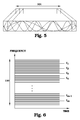
- all carriers were illustrated having the same phase shift at the onset of the useful symbol duration of N fft samples. However, a more realistic could be the one illustrated in Fig. 5, where different carrier presents different phase shifts.
- Fig. 6 illustrates a carrier utilisation for OFDM according to the present invention.
- a large number of carriers are used.
- 4000 carriers could be in use, spread over a frequency range 110.
- the carriers are equidistant, i.e. there is a constant frequency difference between two successive carriers.
- One of the basic concepts of the present invention is the introduction of a new channel that fits into the OFDM frame-work, which is dedicated to transmission of information between nodes that are not necessarily time-synchronised.
- a sub-set f 1 , f 2 , ..., f m of carriers is reserved for transmitting such information.
- the sub-set is also equidistant in frequency, i.e. each carrier in the sub-set is separated from the previous carrier in the sub-set by the same frequency difference.
- Fig. 7 schematically illustrates the association between certain carrier frequencies and base stations (BST). This associative information is available within the communications network.
- the ordinary information transfer in OFDM is as mentioned above based on the phase information of each carrier. This requires a good synchronisation between transmitter and receiver.
- the data transfer is performed as schematically illustrated in Fig. 8A.
- a transmitter of a first node N1 creates a number of orthogonal carriers with phase shifts according to data values to be transmitted.
- CP and roll-on/roll-off sections are added and a signal is transmitted.
- the upper part illustrates such a transmitted signal.
- a single carrier is illustrated, although a multitude of carriers are transmitted simultaneously.
- the start and end of roll-on/roll-off and CP sections are indicated by vertical lines.
- the signal is a pure sinusoidal signal, except for the roll-on/roll off and CP sections.
- a second node N2 receives the signal.
- the node N2 is synchronised with the node N1, which means that N2 will neglect signal information achieved in periods corresponding to CP and roll-on/roll-off sections.
- a template in time dimension is created, as indicated in the middle row of Fig. 8A. Signals arriving during the barred intervals are neglected and only signals arriving between these barred intervals are used for analysis.
- the signal received by the node N2 is indicated in the lower part of Fig. 8A. These signals are pure sinusoidal signals with exactly the same phase shifts as the original ones. An evaluation of the phase shifts then leads to an interpretation of the transferred information.
- Fig. 8B a similar situation is described.
- the nodes N 1 and N2 are not synchronised.
- the upper part is identical to Fig. 8A, since the first node operates in a similar timing as before.
- the time reference of node N2 is, however, now onset a time ⁇ . This means that the time template of node N2 is also onset the difference ⁇ as shown in the middle part of Fig. 8B.
- the resulting signals extracted by node N2 is shown in the lower part of Fig. 8b. It is obvious for anyone skilled in the art that this signal is not a pure sinusoidal signal, which means that the signal also contains components of other frequencies. Since all carriers are distorted in a similar manner, the resulting signal will be severely distorted and any attempts to interpret the informational content will fail. This is the prior-art situation for communication between unsynchronised nodes.
- Fig. 8C illustrates the signalling principles between unsynchronised nodes according to an embodiment of the present invention.
- the node N 1 transmits on a carrier reserved for unsynchronised communication that is assigned to node N 1.
- This sinusoidal signal 99 is continuously transmitted, regardless of any normal roll-on/roll-off or CP sections.
- the node N2 is unsynchronised with node N1 as in Fig. 8B, by a time reference difference of ⁇ .
- the time template of node N2 is as illustrated in the middle of the figure. At the lower part of Fig.
- the received or extracted signal is illustrated. It is obvious that the first extracted OFDM symbol, of which only a part is seen in the figure, contains un-interpretable information. A minus sign ("-") indicates this useless signal in the figure. However, a second extracted OFDM signal 98 does only contain one single sinusoidal frequency. This OFDM symbol can therefore be associated with useful information, which is indicated with a star ("*"). The third extracted OFDM signal again contains non-sinusoidal components at the end of the OFDM signal period and any information of this symbol is of no use.
- every second received OFDM symbol 98 has some sort of informational value.
- the phase of the received signal still is not to trust, since the time reference difference ⁇ , is unknown.
- modulation techniques using pure sinusoidal signals 99 but no absolute phases are possible to use for transferring information.
- Fig. 8D an alternative embodiment of the present invention is illustrated.
- the duration of the pure sinusoidal signal 99 transmitted from node N1 corresponds to three successive OFDM symbols.
- the received and extracted OFDM symbols comprise one nonsense symbol and two symbols comprising pure sinusoidal signals 98.
- the frequency of these two sinusoidal signals 98 is identical.
- there is a relative phase shift ⁇ which uniquely depends on, and therefore can be calculated from, the relation between the absolute frequency and the magnitude of the CP and roll-on/roll-off durations. It is thus easily concluded if the two detected sinusoidal signals 98 originates from the same transmitted sinusoidal signal 99.
- each base station is assigned a set of reserved frequencies.
- the mobile terminal can then listen and try to detect the presence or existence of an un-modulated sinusoid signal 98 that belongs to the reserved set of frequencies.
- the mobile detects the presence of a signal on a frequency reserved for unsynchronised communication it can extract at least the following 4 items of information.
- the cell ID of the base station transmitting the reserved frequency (or frequencies) is a direct mapping of the frequency (or frequencies) used.
- the existence of a certain reserved frequency directly leads to the knowledge that a specific one of the base stations is present relatively close.
- the relative path loss to the new unsynchronised base station is derived from averaging the received signal strength of the reserved signal. The relative path loss then gives information about approximate distances or whether the new base station may be a handover alternative.
- a relative Doppler to the new base station as compared to the present base station is derived.
- An absolute Doppler estimation is achieved by comparing the received frequency of the reserved carrier with a local frequency reference signal. This local frequency reference signal has to be relatively stable.
- the sign of the relative Doppler tells the mobile if it is moving towards the new base station or away from the new base station.
- the mobile can also perform some early steps towards synchronisation.
- the synchronisation is divided into several parts including OFDM symbol synchronisation, frame synchronisation (a frame is assumed to consist of several OFDM symbols) and possibly also super-frame synchronisation (super-frame is assumed to consist of several frames).
- frame synchronisation a frame is assumed to consist of several OFDM symbols
- super-frame synchronisation super-frame is assumed to consist of several frames.
- an estimate of the OFDM symbol synchronisation error can be obtained. If the detected information symbols on average have much higher received energy than the discarded symbols then the OFDM symbol synchronisation error is large. If, on the other hand, the discarded symbols have almost equally large received energy as the detected symbols, then the OFDM symbol synchronisation is much more accurate. This information can be utilised in the later search of perfect OFDM symbol synchronisation, in case the mobile is to perform a handover to the new un-synchronised base station. Perfect frequency synchronisation to the base station is achieved by locking on to the transmitted un-modulated sinusoid of the reserved frequency.
- one basic feature of the invention is that a sub-set of carriers is reserved for unsynchronised communication, e.g. for cell search.
- a sub-set of carriers is reserved for unsynchronised communication, e.g. for cell search.
- the mobile terminal detects the presence of such a carrier it will know that it is transmitted from another base station.
- the mobile can detect this signal even if it is not time synchronised to the base station that transmits it.
- the frequency of the reserved carrier that the mobile detects is a direct mapping of the cell ID of the base station that transmits the signal.
- the carrier frequency reserved e.g. for cell search and broadcasting of information to unsynchronised mobiles should have a modulation format with the following two properties.
- the baud rate of the unsynchronised information must be at most half the original OFDM symbol rate.
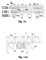
- Fig. 9 illustrates an embodiment of unsynchronised communication according to the present invention, In this figure, the roll-on/roll-off and CP sections are neglected for simplify the reading of the figures. However, these are of course present in analogy with previous figures.
- an amplitude modulation is used.
- the amplitude modulation consists of turning the sinusoidal signal 99 on and off, respectively according to certain rules.
- a transmitting node N 1 provides a sinusoidal signal 99 of a frequency corresponding to a reserved carrier. For sending a "1”, the node N1 turns on the sinusoidal signal 99 during two consecutive OFDM symbols. For sending a "O", the node N1 turns off the sinusoidal signal 99 during two consecutive OFDM symbols, In the example given in Fig.
- the node N1 transmits the data sequence "1101", by turning on the sinusoidal signal 99 during 2 times 2 OFDM symbol durations, by turning it off during 2 OFDM symbol durations and finally turning it on again during 2 OFDM symbol durations. Note that there is no phase shift allowed between the first and second OFDM symbol, between the third and fourth OFDM symbol and between the seventh and eighth OFDM symbol. However, if required, there might be a phase shift between the second and third OFDM symbol.
- the receiving node N2 records the signals illustrated in the middle row. Pure sinusoidal signals 98 are received in at least every second OFDM symbol. There might also be incidental sinusoidal signals in the intermediate symbols as well, marked with (*). The receiver concludes which set of every second symbol that normally contains rubbish and discards these OFDM symbols. This altering of received OFDM symbols is illustrated in the bottom line of Fig. 9 and is the explanation of why only at the most half the baud rate can be achieved. The node N2 can now interpret every remaining OFDM "symbol” comprising a sinusoidal signal as a "1" and every empty OFDM “symbol” as a "0". In the example of Fig. 9, the sequence "1101" is detected.
- a transmitter is associated with two frequencies for unsynchronised communication.
- both frequencies are allowed to contain a sinusoidal signal 99A, 99B.
- "10” corresponds to a sinusoidal signal 99A at only one frequency
- "01” corresponds to a sinusoidal signal 99B at only the other frequency.
- no signals at all are sent.
- the receiving and filtering procedures are in analogy with earlier embodiments and the receiver will easily interpret the transmitted information.
- the information rate can be increased.
- the reservation of carriers for unsynchronised communication decreases the total information transfer, the unsynchronised information rate should be kept as low as possible. Only very important data should be communicated such a way, preferably only data assisting in e.g. handover or paging procedures.
- the absolute phase of the sinusoidal signal can not be used for transferring data, since the synchronisation difference ⁇ is not generally known.
- a relative phase can be used, i.e. the data that is transmitted could be differentially encoded.
- An example of a PSK system is illustrated in Figs. 11A-C.
- a first sinusoidal signal 120 is transmitted during two OFDM symbol intervals.
- the phase shift of this signal corresponds to the point 130 in the PQ-diagram.
- an additional phase shift ⁇ is introduced in the second OFDM symbol interval.
- a second sinusoidal signal 121 is transmitted during the two following OFDM symbol intervals.
- the relative phase ⁇ is to be coded according to information to be transmitted, in this case the bits "11".
- the phase shift should correspond to the point 131 in the PQ-diagram, i.e. a phase shift of 180°.
- a sinusoidal signal 122 is received at the receiver side.
- the phase of the signal 122 corresponds to a point 132 in the PQ-diagram.
- a second signal 123 is received.
- this signal is not a pure sinusoidal signal and is therefore discarded.
- a next sinusoidal signal 124 is received in the next OFDM symbol interval.
- the phase - ⁇ 2 of signal 124 corresponds to a point 134 in the PQ-diagram.
- phase shift ⁇ should be introduced twice between the two signals 122 and 124.
- ⁇ is easily deduced from the carrier frequency and time durations of roll-on/roll-off and PC. This is described in detail further below. From this it can be concluded that if no phase shift at all were present at the transmission side between signals 120 and 121, the detected phase of signal 124 would be at point 133 in the PQ-diagram.
- phase rotation ⁇ on a carrier performing n complete rotations during the useful OFDM signal can be expressed as: where ⁇ x ⁇ denotes the largest integer smaller than or equal to x.
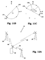
- Fig. 12A illustrates a communications system, where three base stations 20 are within radio communication distance with a mobile terminal 30.
- the mobile terminal is connected and synchronised to the closest base station by an active link 60.
- the mobile terminal 30 continuously or quasi-continuously searches for neighbour base stations.
- Such communication has to be performed over unsynchronised links 65.
- the information that is of particular interest during an initial search stage is first of all the existence of neighbour base stations, and further information like e.g. the cell load in other base stations. This information is relevant when taking any decision that a handover procedure should be initiated.
- a synchronisation message can for instance be transmitted as a special broadcast information on the reserved carriers.
- Fig. 12B illustrates another situation.
- the mobile terminal 30 is not synchronised to any base station 20. This could e.g. be the situation when the mobile terminal 30 is turned on and starts to End any communications network to communicate with.
- the mobile terminal 30 has its own internal synchronisation and all communication with base stations in the vicinity has to be performed via unsynchronised messages in an initial phase.
- This situation is very demanding in prior art in terms of processing capacity, battery power and time.
- some initial assisting information such as a ruff frame synchronisation or an available random access resource can be derived, this reduces these demands considerably.
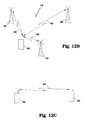
- Fig. 12B could also illustrate the situation, in which the mobile terminal 30 is connected to the communications system in idle mode.
- the mobile terminal 30 is then not synchronised with any particular base station 20, but the base stations 20 know that the mobile terminal 30 a short while ago was present within their coverage area.
- a paging is performed, in order to determine where the mobile terminal 30 is situated.
- Such a paging message can with advantage be broadcast using a carrier intended for unsynchronised communication according to the present invention.
- unsynchronised communication should also be possible to perform e.g. between two base stations, e.g. for exchanging resource management information over the air.
- Unsynchronised communication is also possible to perform directly between mobile terminals 30, as illustrated in Fig. 12C.
- the carrier frequency there is probably no pre-defined relation between the carrier frequency that is used and the particular device.
- a carrier commonly assigned for such communication has to be used, or if the mobile terminals 30 are presently connected to any network, the network or networks could assist in temporarily assigning such a carrier frequency to the communication.
- a constant sinusoidal signal can be generated by an OFDM transmitter in different ways.
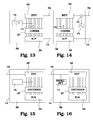
- One embodiment is illustrated in Fig 13.
- the signal processor 28 of a transmitter is shown in more detail.
- one carrier is reserved for unsynchronised communication from this particular transmitter.
- a data symbol generator 71 supplies a value intended for this particular carrier.
- a terminator means 74 terminates any signals on the reserved carrier provided from the encoder. On such carriers that rotate an integer number of times during the roll-on, the roll-off, and the cyclic prefix durations a constant data symbol can be transmitted from the symbol generator 71.
- a constant sinus can be transmitted on any carrier by continuously rotating the data symbol on that carrier to compensate for the phase rotations during the cyclic prefix and the roll on/off. If the symbol generator 71 transmits the same data symbol in two consecutive OFDM symbols and rotates the second data symbol in order to compensate for the phase shift ⁇ in the cyclic prefix and in the roll-on and roll-off, then there will be a sinusoidal signal, which lasts for at least two OFDM symbol durations.
- the phase shift ⁇ is easily calculated as discussed further above. If the sinusoidal signal is to carry information modulated as well, the symbol generator 71 is controlled accordingly, e.g. by being switched on and off or by introducing further phase shifts, according to the discussions further above.
- the resulting signal is provided on a signal processor output 70.
- a carrier in the IFFT can be switched off and a sinusoidal signal of the corresponding frequency can simply be added 72 in the time domain by a signal generator 73.
- the signal generator 73 is controlled accordingly, e.g. by being switched on and off or by introducing further phase shifts, according to the discussions further above.
- a signal processor in a receiver can look like the one illustrated in Fig. 15.
- An input signal is received at a signal processor input 75.
- the FFT 35 one (or in general several) of the transformed values is not allowed to reach the decoder 37. Instead a symbol interpreter 76 is introduced. In this symbol interpreter, any procedure connected to the reception of unsynchronised OFDM communication is performed, according to the discussions above.
- Fig. 16 illustrates an alternative embodiment of a receiver signal processor.
- the reserved carrier is simply terminated at the FFT 35 or at the connection to the decoder 37.
- a second (smaller) FFT 77 is connected directly to the input 75, experiencing the same signal as the main FFT 35.
- the second FFT 77 is then preferably arranged to only select a few frequencies to analyse.
- Such small FFT 77 can be designed to be much simpler than the main FFT 35, which doesn't add any significant costs to the entire signal processor 38. Instead, the operation of the small FFT 35 requires less time and less processor power and therefore also less battery power. Particularly cheap and simple FFTs can be achieved if the reserved carriers are selected equidistant in frequency, as mentioned further above.
- the encoder and decoder are illustrated as units operating in parallel on several data.
- the encoder/decoder can change position with the parallel-to serial and serial-to-parallel converters, respectively.
- the decoding/encoding is performed on serial data.
- the terminator means 74 can then be placed on either side of the serial-to-parallel converter 29 at the transmitter, and symbol interpreter 76 can be placed before or after the parallel-to-serial converter 39 at the receiver side.
- the method according to the present invention can be summarised by referring to a flow diagram of Fig. 17, in which the main steps of an embodiment of a method according to the present invention are illustrated.
- the procedure starts in step 200.
- a number of carriers of an OFDM system are reserved for unsynchronised communication
- a sinusoidal signal is transmitted at such a reserved carrier over a time period corresponding to at least two consecutive OFDM symbols.
- the sinusoidal signal is received in step 206 and interpreted in step 208.
- the procedure ends in step 210.
Landscapes
- Engineering & Computer Science (AREA)
- Signal Processing (AREA)
- Computer Networks & Wireless Communication (AREA)
- Mobile Radio Communication Systems (AREA)
Priority Applications (11)
| Application Number | Priority Date | Filing Date | Title |
|---|---|---|---|
| EP03104617A EP1542418A1 (fr) | 2003-12-10 | 2003-12-10 | Système multiporteuses sans fil avec sous-pourteuses réservées pour la communication entre des noeuds non-synchronisés |
| EP04804626A EP1695503B1 (fr) | 2003-12-10 | 2004-12-01 | Systeme multiporteuse sans fil comprenant des sous-porteuses reservees a une communication entre des noeuds non synchronises |
| AU2004300288A AU2004300288B2 (en) | 2003-12-10 | 2004-12-01 | Wireless multicarrier system with subcarriers reserved for communication between unsynchronized nodes |
| US10/581,995 US7616556B2 (en) | 2003-12-10 | 2004-12-01 | Wireless multicarrier system with subcarriers reserved for communication between unsynchronized nodes |
| CN200480036644A CN100579099C (zh) | 2003-12-10 | 2004-12-01 | 具有为非同步节点之间通信而保留的子载波的无线多载波系统 |
| JP2006543534A JP2007514353A (ja) | 2003-12-10 | 2004-12-01 | 非同期のノード間の通信のために予約されるサブキャリアを有する無線マルチキャリアシステム |
| KR1020067011472A KR100819608B1 (ko) | 2003-12-10 | 2004-12-01 | 비동기 노드 사이의 통신용으로 예약된 부반송파를 가진 무선 다중 반송파 시스템 |
| HK07106861.6A HK1102092B (en) | 2003-12-10 | 2004-12-01 | Wireless multicarrier system with subcarriers reserved for communication between unsynchronized nodes |
| ZA200603622A ZA200603622B (en) | 2003-12-10 | 2004-12-01 | Wireless multicarrier system with subcarriers reserved for communication between unsynchronized nodes |
| PCT/EP2004/053193 WO2005060194A1 (fr) | 2003-12-10 | 2004-12-01 | Systeme multiporteuse sans fil comprenant des sous-porteuses reservees a une communication entre des noeuds non synchronises |
| TW093138436A TWI373240B (en) | 2003-12-10 | 2004-12-10 | Method for communication between nodes, node, and wireless communication system |
Applications Claiming Priority (1)
| Application Number | Priority Date | Filing Date | Title |
|---|---|---|---|
| EP03104617A EP1542418A1 (fr) | 2003-12-10 | 2003-12-10 | Système multiporteuses sans fil avec sous-pourteuses réservées pour la communication entre des noeuds non-synchronisés |
Publications (1)
| Publication Number | Publication Date |
|---|---|
| EP1542418A1 true EP1542418A1 (fr) | 2005-06-15 |
Family
ID=34486381
Family Applications (2)
| Application Number | Title | Priority Date | Filing Date |
|---|---|---|---|
| EP03104617A Withdrawn EP1542418A1 (fr) | 2003-12-10 | 2003-12-10 | Système multiporteuses sans fil avec sous-pourteuses réservées pour la communication entre des noeuds non-synchronisés |
| EP04804626A Expired - Lifetime EP1695503B1 (fr) | 2003-12-10 | 2004-12-01 | Systeme multiporteuse sans fil comprenant des sous-porteuses reservees a une communication entre des noeuds non synchronises |
Family Applications After (1)
| Application Number | Title | Priority Date | Filing Date |
|---|---|---|---|
| EP04804626A Expired - Lifetime EP1695503B1 (fr) | 2003-12-10 | 2004-12-01 | Systeme multiporteuse sans fil comprenant des sous-porteuses reservees a une communication entre des noeuds non synchronises |
Country Status (9)
| Country | Link |
|---|---|
| US (1) | US7616556B2 (fr) |
| EP (2) | EP1542418A1 (fr) |
| JP (1) | JP2007514353A (fr) |
| KR (1) | KR100819608B1 (fr) |
| CN (1) | CN100579099C (fr) |
| AU (1) | AU2004300288B2 (fr) |
| TW (1) | TWI373240B (fr) |
| WO (1) | WO2005060194A1 (fr) |
| ZA (1) | ZA200603622B (fr) |
Cited By (4)
| Publication number | Priority date | Publication date | Assignee | Title |
|---|---|---|---|---|
| US20090245331A1 (en) * | 2008-03-28 | 2009-10-01 | Qualcomm Incorporated | Signaling message transmission in a wireless communication network |
| WO2009120943A3 (fr) * | 2008-03-28 | 2010-06-10 | Qualcomm Incorporated | Émission de messages de signalisation en utilisant des signaux de balise |
| US8848581B2 (en) | 2008-06-27 | 2014-09-30 | Nokia Corporation | Unsynchronized signaling in radio systems using frequency domain processing |
| US12470445B2 (en) | 2023-10-26 | 2025-11-11 | Qualcomm Incorporated | Multi-carrier on-off keying communications |
Families Citing this family (16)
| Publication number | Priority date | Publication date | Assignee | Title |
|---|---|---|---|---|
| US7941091B1 (en) * | 2006-06-19 | 2011-05-10 | Rf Magic, Inc. | Signal distribution system employing a multi-stage signal combiner network |
| JP2008017245A (ja) * | 2006-07-07 | 2008-01-24 | Fujitsu Ltd | 無線基地局装置 |
| JP5008994B2 (ja) | 2007-01-30 | 2012-08-22 | 京セラ株式会社 | 通信システム、基地局、端末及び通信方法 |
| TWI466478B (zh) * | 2007-09-14 | 2014-12-21 | Koninkl Philips Electronics Nv | 致能非同步無線裝置間的通信之裝置及方法 |
| US8249029B2 (en) * | 2008-03-28 | 2012-08-21 | Qualcomm Incorporated | Low reuse preamble for a wireless communication network |
| DE102009060593A1 (de) * | 2008-12-30 | 2010-07-08 | Atmel Automotive Gmbh | System, Verfahren und Schaltung zur Entfernungsmessung zwischen zwei Knoten eines Funknetzes |
| CN101771641B (zh) * | 2008-12-31 | 2014-04-30 | 中兴通讯股份有限公司 | P-sch的配置方法和装置、p-sch的同步信号产生方法和装置 |
| WO2010087665A2 (fr) * | 2009-02-02 | 2010-08-05 | Lg Electronics Inc. | Procédé et dispositif de transmission de données par au moins une station de base dans un système de communication sans fil |
| US8619908B2 (en) * | 2009-12-02 | 2013-12-31 | Harris Corporation | Wireless ranging system and related methods |
| US8948154B2 (en) * | 2010-02-10 | 2015-02-03 | Qualcomm Incorporated | Method and apparatus for sending and receiving a low-complexity transmission in a wireless communication system |
| US9148851B2 (en) * | 2010-08-20 | 2015-09-29 | Lg Electronics Inc. | Method and terminal for searching for an access point |
| JP2013187833A (ja) * | 2012-03-09 | 2013-09-19 | Ntt Docomo Inc | 送信装置及び送信フレーム構成方法 |
| CN104335674B (zh) * | 2013-03-07 | 2019-03-29 | 松下知识产权经营株式会社 | 通信装置及通信方式的判定方法 |
| JP6373158B2 (ja) * | 2014-10-15 | 2018-08-15 | 株式会社メガチップス | データ受信装置、プログラムおよび集積回路 |
| US9648616B2 (en) * | 2015-01-15 | 2017-05-09 | Nokia Solutions And Networks Oy | Method and apparatus for implementing efficient low-latency uplink access |
| CN108702595B (zh) * | 2017-02-03 | 2021-07-27 | 瑞典爱立信有限公司 | 用于执行上行链路传输的方法和设备 |
Family Cites Families (21)
| Publication number | Priority date | Publication date | Assignee | Title |
|---|---|---|---|---|
| SE514809C2 (sv) * | 1994-07-13 | 2001-04-30 | Hd Divine Ab | Metod och anordning för synkronisering av sändare och mottagare i digitalt system |
| US6334219B1 (en) * | 1994-09-26 | 2001-12-25 | Adc Telecommunications Inc. | Channel selection for a hybrid fiber coax network |
| US6078571A (en) * | 1997-09-19 | 2000-06-20 | Motorola, Inc. | Apparatus and method for transmitting beacon signals in a communication system |
| JP3127918B1 (ja) * | 1999-07-14 | 2001-01-29 | 住友電気工業株式会社 | 路車間通信システム並びに路上通信局及び車載移動局 |
| JP3485860B2 (ja) * | 2000-03-27 | 2004-01-13 | 松下電器産業株式会社 | 基地局装置及び無線通信方法 |
| EP1279265A1 (fr) * | 2000-04-25 | 2003-01-29 | Interdigital Technology Corporation | Detection aveugle de decalage de porteuse destinee a des systeme de communication numeriques modules en quadrature |
| JP2002076992A (ja) * | 2000-09-05 | 2002-03-15 | Nec Corp | 周波数調整回路 |
| US6985433B1 (en) * | 2000-09-15 | 2006-01-10 | Flarion Technologies, Inc. | Methods and apparatus for determining minimum cyclicprefix durations |
| US20080095121A1 (en) * | 2002-05-14 | 2008-04-24 | Shattil Steve J | Carrier interferometry networks |
| JP3512173B2 (ja) * | 2001-01-18 | 2004-03-29 | 松下電器産業株式会社 | ピーク電力抑圧装置およびピーク電力抑圧方法 |
| WO2002058331A2 (fr) * | 2001-01-18 | 2002-07-25 | Koninklijke Philips Electronics N.V. | Signalisation par diffusion sans connexion |
| US20020172186A1 (en) * | 2001-04-09 | 2002-11-21 | Peter Larsson | Instantaneous joint transmit power control and link adaptation for RTS/CTS based channel access |
| US7206350B2 (en) * | 2001-06-11 | 2007-04-17 | Unique Broadband Systems, Inc. | OFDM multiple sub-channel communication system |
| US7962162B2 (en) * | 2001-08-07 | 2011-06-14 | At&T Intellectual Property Ii, L.P. | Simulcasting OFDM system having mobile station location identification |
| US7269151B2 (en) * | 2002-04-22 | 2007-09-11 | Cognio, Inc. | System and method for spectrum management of a shared frequency band |
| CN1248439C (zh) * | 2002-08-22 | 2006-03-29 | 上海交通大学 | 正交频分复用系统中频率同步实现方法 |
| US6993333B2 (en) * | 2003-10-16 | 2006-01-31 | Flarion Technologies, Inc. | Methods and apparatus of improving inter-sector and/or inter-cell handoffs in a multi-carrier wireless communications system |
| US7092353B2 (en) * | 2003-10-17 | 2006-08-15 | Qualcomm Incorporated | Carrier search methods and apparatus |
| JP4329500B2 (ja) * | 2003-11-07 | 2009-09-09 | ソニー株式会社 | 無線通信システム、無線通信装置及び無線通信方法、並びにコンピュータ・プログラム |
| US7047009B2 (en) * | 2003-12-05 | 2006-05-16 | Flarion Technologies, Inc. | Base station based methods and apparatus for supporting break before make handoffs in a multi-carrier system |
| US7599420B2 (en) * | 2004-07-30 | 2009-10-06 | Rearden, Llc | System and method for distributed input distributed output wireless communications |
-
2003
- 2003-12-10 EP EP03104617A patent/EP1542418A1/fr not_active Withdrawn
-
2004
- 2004-12-01 US US10/581,995 patent/US7616556B2/en not_active Expired - Fee Related
- 2004-12-01 AU AU2004300288A patent/AU2004300288B2/en not_active Ceased
- 2004-12-01 KR KR1020067011472A patent/KR100819608B1/ko not_active Expired - Fee Related
- 2004-12-01 WO PCT/EP2004/053193 patent/WO2005060194A1/fr not_active Ceased
- 2004-12-01 ZA ZA200603622A patent/ZA200603622B/en unknown
- 2004-12-01 CN CN200480036644A patent/CN100579099C/zh not_active Expired - Fee Related
- 2004-12-01 EP EP04804626A patent/EP1695503B1/fr not_active Expired - Lifetime
- 2004-12-01 JP JP2006543534A patent/JP2007514353A/ja active Pending
- 2004-12-10 TW TW093138436A patent/TWI373240B/zh not_active IP Right Cessation
Non-Patent Citations (2)
| Title |
|---|
| ENGSTROM B ET AL: "A SYSTEM FOR TEST OF MULTIACCESS METHODS BASED ON OFDM", PROCEEDINGS OF THE VEHICULAR TECHNOLOGY CONFERENCE. STOCKHOLM, JUNE 8 - 10, 1994, NEW YORK, IEEE, US, vol. 3 CONF. 44, 8 June 1994 (1994-06-08), pages 1843 - 1845, XP000497744, ISBN: 0-7803-1928-1 * |
| KAPOOR S ET AL: "PILOT ASSISTED SYNCHRONIZATION FOR WIRELESS OFDM SYSTEMS OVER FAST TIME VARYING FADING CHANNELS", VTC'98. 48TH. IEEE VEHICULAR TECHNOLOGY CONFERENCE. OTTAWA, CANADA, MAY 18 - 21, 1998, IEEE VEHICULAR TECHNOLOGY CONFERENCE, NEW YORK, NY: IEEE, US, vol. 3 CONF. 48, 18 May 1998 (1998-05-18), pages 2077 - 2080, XP000903385, ISBN: 0-7803-4321-2 * |
Cited By (11)
| Publication number | Priority date | Publication date | Assignee | Title |
|---|---|---|---|---|
| US20090245331A1 (en) * | 2008-03-28 | 2009-10-01 | Qualcomm Incorporated | Signaling message transmission in a wireless communication network |
| WO2009120943A3 (fr) * | 2008-03-28 | 2010-06-10 | Qualcomm Incorporated | Émission de messages de signalisation en utilisant des signaux de balise |
| WO2009120941A3 (fr) * | 2008-03-28 | 2010-12-09 | Qualcomm Incorporated | Transmission de messages de signalisation dans un réseau de communication sans fil |
| CN102308514A (zh) * | 2008-03-28 | 2012-01-04 | 高通股份有限公司 | 通过时频平面中选择的子载波或正交序列进行的无线网络中的信令消息传输 |
| KR101296772B1 (ko) * | 2008-03-28 | 2013-08-14 | 퀄컴 인코포레이티드 | 무선 통신 네트워크에서에서의 시그널링 메시지 송신 |
| US8995559B2 (en) | 2008-03-28 | 2015-03-31 | Qualcomm Incorporated | Signaling message transmission in a wireless communication network |
| CN102308514B (zh) * | 2008-03-28 | 2015-11-25 | 高通股份有限公司 | 通过时频平面中选择的子载波或正交序列进行的无线网络中的信令消息传输 |
| US9276787B2 (en) | 2008-03-28 | 2016-03-01 | Qualcomm Incorporated | Transmission of signaling messages using beacon signals |
| US9949276B2 (en) | 2008-03-28 | 2018-04-17 | Qualcomm Incorporated | Signaling message transmission in a wireless communication network |
| US8848581B2 (en) | 2008-06-27 | 2014-09-30 | Nokia Corporation | Unsynchronized signaling in radio systems using frequency domain processing |
| US12470445B2 (en) | 2023-10-26 | 2025-11-11 | Qualcomm Incorporated | Multi-carrier on-off keying communications |
Also Published As
| Publication number | Publication date |
|---|---|
| TWI373240B (en) | 2012-09-21 |
| CN100579099C (zh) | 2010-01-06 |
| TW200531486A (en) | 2005-09-16 |
| EP1695503A1 (fr) | 2006-08-30 |
| US7616556B2 (en) | 2009-11-10 |
| US20070002725A1 (en) | 2007-01-04 |
| KR100819608B1 (ko) | 2008-04-07 |
| JP2007514353A (ja) | 2007-05-31 |
| EP1695503B1 (fr) | 2012-10-24 |
| CN1890938A (zh) | 2007-01-03 |
| AU2004300288A1 (en) | 2005-06-30 |
| KR20060101525A (ko) | 2006-09-25 |
| AU2004300288B2 (en) | 2009-03-19 |
| HK1102092A1 (zh) | 2007-11-02 |
| ZA200603622B (en) | 2007-09-26 |
| WO2005060194A1 (fr) | 2005-06-30 |
Similar Documents
| Publication | Publication Date | Title |
|---|---|---|
| EP1695503B1 (fr) | Systeme multiporteuse sans fil comprenant des sous-porteuses reservees a une communication entre des noeuds non synchronises | |
| US7580400B2 (en) | Apparatus and method for generating preamble signal for cell identification in an orthogonal frequency division multiplexing system | |
| US10764006B2 (en) | Method and apparatus for generating pilot tone in orthogonal frequency division multiplexing access system, and method and apparatus for estimating channel using it | |
| US7675841B2 (en) | Apparatus and method for generating a preamble sequence in an orthogonal frequency division multiplexing communication system | |
| US20050002369A1 (en) | Apparatus and method for cell search in mobile communication system using a multiple access scheme | |
| EP1971064B1 (fr) | Canal d'accès initial pour réseaux de communication mobile extensibles sans fil | |
| KR20100046565A (ko) | 무선 통신 시스템에서 순환 전치 길이 변경 방법 및 이를 위한 시스템 | |
| EP2338306B1 (fr) | Partitionnement en mode commun de canaux à large bande | |
| US20090135802A1 (en) | Scalable bandwidth system, radio base station apparatus, synchronous channel transmitting method and transmission method | |
| US20060013594A1 (en) | Apparatus and method for synchronizing optic repeater in communication system using time division OFDM scheme | |
| JP5490141B2 (ja) | 広帯域無線通信システムにおける副同期チャネルの送受信装置及び方法 | |
| KR100755537B1 (ko) | Ofdm 셀룰러 시스템의 하향링크신호 전송방법, 그전송장치, 수신단말의 셀 탐색방법 및 그 탐색장치 | |
| HK1102092B (en) | Wireless multicarrier system with subcarriers reserved for communication between unsynchronized nodes | |
| KR20100003771A (ko) | 광대역 무선통신시스템에서 공존모드를 위한 셀 아이디매핑 장치 및 방법 | |
| HK1120698B (en) | Initial access channel for scalable wireless mobile communication networks | |
| HK1120698A (en) | Initial access channel for scalable wireless mobile communication networks | |
| HK1117314B (en) | Initial access channel for scalable wireless mobile communication networks |
Legal Events
| Date | Code | Title | Description |
|---|---|---|---|
| PUAI | Public reference made under article 153(3) epc to a published international application that has entered the european phase |
Free format text: ORIGINAL CODE: 0009012 |
|
| AK | Designated contracting states |
Kind code of ref document: A1 Designated state(s): AT BE BG CH CY CZ DE DK EE ES FI FR GB GR HU IE IT LI LU MC NL PT RO SE SI SK TR |
|
| AX | Request for extension of the european patent |
Extension state: AL LT LV MK |
|
| AKX | Designation fees paid | ||
| REG | Reference to a national code |
Ref country code: DE Ref legal event code: 8566 |
|
| STAA | Information on the status of an ep patent application or granted ep patent |
Free format text: STATUS: THE APPLICATION IS DEEMED TO BE WITHDRAWN |
|
| 18D | Application deemed to be withdrawn |
Effective date: 20060302 |