EP1542484A1 - Système de communication radiocellulaire, procédé de communication radiocellulaire and procédé de réception Rake - Google Patents
Système de communication radiocellulaire, procédé de communication radiocellulaire and procédé de réception Rake Download PDFInfo
- Publication number
- EP1542484A1 EP1542484A1 EP20040090486 EP04090486A EP1542484A1 EP 1542484 A1 EP1542484 A1 EP 1542484A1 EP 20040090486 EP20040090486 EP 20040090486 EP 04090486 A EP04090486 A EP 04090486A EP 1542484 A1 EP1542484 A1 EP 1542484A1
- Authority
- EP
- European Patent Office
- Prior art keywords
- digital
- transmitter
- baseband
- modulation signal
- receivers
- Prior art date
- Legal status (The legal status is an assumption and is not a legal conclusion. Google has not performed a legal analysis and makes no representation as to the accuracy of the status listed.)
- Ceased
Links
- 238000000034 method Methods 0.000 title claims abstract description 38
- 238000004891 communication Methods 0.000 title claims abstract description 31
- 230000001413 cellular effect Effects 0.000 title claims abstract description 27
- 230000005540 biological transmission Effects 0.000 claims abstract description 31
- 238000006243 chemical reaction Methods 0.000 claims description 8
- 238000010586 diagram Methods 0.000 description 9
- 230000003287 optical effect Effects 0.000 description 4
- 238000009792 diffusion process Methods 0.000 description 2
- 230000010363 phase shift Effects 0.000 description 2
- 230000008054 signal transmission Effects 0.000 description 2
- 230000015556 catabolic process Effects 0.000 description 1
- 238000006731 degradation reaction Methods 0.000 description 1
- 239000000284 extract Substances 0.000 description 1
- 238000010295 mobile communication Methods 0.000 description 1
Images



Classifications
-
- H—ELECTRICITY
- H04—ELECTRIC COMMUNICATION TECHNIQUE
- H04B—TRANSMISSION
- H04B1/00—Details of transmission systems, not covered by a single one of groups H04B3/00 - H04B13/00; Details of transmission systems not characterised by the medium used for transmission
- H04B1/69—Spread spectrum techniques
- H04B1/707—Spread spectrum techniques using direct sequence modulation
- H04B1/7097—Interference-related aspects
- H04B1/711—Interference-related aspects the interference being multi-path interference
- H04B1/7115—Constructive combining of multi-path signals, i.e. RAKE receivers
-
- H—ELECTRICITY
- H04—ELECTRIC COMMUNICATION TECHNIQUE
- H04B—TRANSMISSION
- H04B1/00—Details of transmission systems, not covered by a single one of groups H04B3/00 - H04B13/00; Details of transmission systems not characterised by the medium used for transmission
- H04B1/06—Receivers
- H04B1/10—Means associated with receiver for limiting or suppressing noise or interference
- H04B1/1081—Reduction of multipath noise
Definitions
- the invention relates to a cellular radio communication system in which a baseband and a transmitter-receiver are connected via a transmission line, a cellular radio communication method and a rake reception method.
- Fig. 1 is a diagram showing three cells in the structure of a conventional cellular radio communication system.
- a data signal from a switching exchange 25 is converted to a radio signal by a radio base station 21 and sent to the mobile terminal 91 in the cell 31.
- a radio signal from the mobile terminal 91 is received by the radio base station 21 and converted to a data signal to be sent to the switching exchange 25.
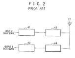
- Fig. 2 shows the structure of a conventional radio base station.
- a data signal input to a modulator 41 is modulated according to a modulation method such as PSK (Phase Shift Keying), QAM (Quadrature Amplitude Modulation), CDMA (Code Division Multiple Access) and OFDM (Orthogonal Frequency Division Multiplexing), and amplified by a transmitter 43.
- a radio signal is output from an antenna 17 and reaches to a mobile terminal.
- a radio signal sent from the mobile terminal is received by the antenna 17, amplified by a receiver 44 and demodulated to a data signal by a demodulator 42.
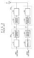
- Fig. 3 shows the structure of another conventional radio base station.
- the radio base station comprises a baseband 58 including a modulator 51 and a demodulator 52, and a transmitter-receiver 59 including a transmitter 55 and a receiver 56.
- the baseband 58 and the transmitter- receiver 59 are connected via a transmission line 57.
- the transmission line 57 is an optical cable, an optical signal is transmitted therethrough.
- the transmission line 57 is a metallic cable, an electric signal is transmitted therethrough.
- the electric power for transmission and reception can be effectively used by placing the transmitter-receiver 59 near an antenna to decrease the electric power loss between the transmitter-receiver 59 and the antenna 17.
- the Japanese Patent No. 2858514 discloses a typical example of a conventional radio communication system as described above, which realizes the miniaturization of a master station while suppressing degradation of transmission quality.
- the baseband is not used effectively because, in the structure of the radio base station, the baseband and the transmitter-receiver are provided so as to correspond one-to-one with each other.
- the structure of the radio base station only has a small degree of freedom.
- RAKE reception is performed by using only multipath components of radio signals received from one antenna of the base station, which limits improving the effectiveness of rake reception.
- a cellular radio communication system comprises one baseband and first to Nth transmitter-receivers connected with each other via a transmission line.
- the baseband comprises a modulator for producing modulation signals to be transmitted from the first to Nth transmitter-receivers by a digital process and a demodulator for demodulating digital modulation signals, which have been received by the first to Nth transmitter-receivers and undergone analog-to-digital conversion, by a digital process.
- the transmitter-receiver comprises a digital-to-analog converter for converting a digital modulation signal to a modulation signal to be transmitted and an analog-to-digital converter for converting a received modulation signal to a digital modulation signal.
- a cellular radio communication system comprises first to Mth basebands and first to Nth transmitter-receivers connected with each other via a transmission line.
- Each of the basebands comprises a modulator for producing a modulation signal to be transmitted by a plurality of transmitter-receivers associated with the baseband by a digital process and a demodulator for demodulating digital modulation signals, which have been received by the plurality of transmitter-receivers associated with the baseband and undergone analog-to-digital conversion, by a digital process.
- the transmitter-receiver comprises a digital-to-analog converter for converting a digital modulation signal to a modulation signal to transmit and an analog-to-digital converter for converting a received modulation signal to a digital modulation signal.
- the transmitter-receivers associated with each of the basebands may be changed.
- a cellular radio communication method applied to a cellular radio communication system comprising one baseband and first to Nth transmitter-receivers connected with each other via a transmission line, comprising the steps of: producing, at the baseband, a modulation signal to be sent by each of the first to Nth transmitter-receivers by a digital process; converting, at the transmitter-receiver, a digital modulation signal to a modulation signal to be sent and outputting the signal from an antenna; converting, at the transmitter-receiver, a modulation signal received by the antenna to a digital modulation signal; and demodulating, at the baseband, a digital modulation signal, which has been received and undergone analog-to-digital conversion at each of the first to Nth transmitter-receivers, by a digital process.
- a cellular radio communication method applied to a cellular radio communication system comprising first to Mth basebands and first to Nth transmitter-receivers connected with each other via a transmission line, comprising the steps of: modulating, at the baseband, signals to produce modulation signals to be sent by a plurality of transmitter-receivers associated with the baseband by a digital process; converting, at the transmitter-receiver, a digital modulation signal to a modulation signal to be sent and outputting the signal from an antenna; converting, at the transmitter-receiver, a modulation signal received by the antenna to a digital modulation signal; and demodulating, at the baseband, digital modulation signals, which have been received and undergone analog-to-digital conversion at the plurality of transmitter-receivers associated with the baseband, by a digital process.
- the transmitter-receivers associated with each of the basebands may be changed.
- Multiple multipath components may be produced from CDMA signals received by the transmitter-receivers in multiple cells to select and synthesize high-level components.
- each ofN pieces of base stations is comprised of a baseband 71 and first to Nth transmitter-receivers connected via a transmission line 68.
- the baseband 71 comprises a modulator 61, a demodulator 62 and a transmission-reception interface 63.
- Each transmitter-receiver is comprised of a digital-to-analog converter 64, an analog-to-digital converter 65, a transmitter 66, a receiver 67 and a transmission-reception interface 63.
- One baseband carries out baseband operations for the first to Nth transmitter-receivers.
- the baseband 71 performs digital processing including CPU software processing by using a digital signal. That is, the baseband 71 performs time-sharing processing or parallel processing by one or more digital processing circuits.
- the modulator 61 performs modulation by a modulation method such as PSK (Phase-Shift Keying), QAM (Quadrature Amplitude Modulation), CDMA (Code Division Multiple Access), OFDM (Orthogonal Frequency Division Multiplexing) or multiplex modulation by a plurality of modulation methods.
- the modulator 61 produces modulation signals to be sent by the first to Nth transmitter-receivers by the time-sharing processing or the parallel processing.
- the demodulator 62 performs demodulation by a demodulation method such as PSK, QAM, CDMA, OFDM or multiplex demodulation by a plurality of demodulation methods.
- the demodulator 62 demodulates modulation signals received from the first to Nth transmitter-receivers by the time-sharing processing or the parallel processing.
- the baseband 71 and the first to Nth transmitter-receivers are connected by the transmission line 68 and transmit and receive digital signals through the transmission-reception interfaces 63.
- the transmission line(s) include N pieces of transmission lines connecting the baseband 71 and the first to Nth transmitter-receivers, one virtual transmission line time-shared by the baseband 71 and the first to Nth transmitter-receivers for digital signal transmission such as the Internet using TCP/IP protocol, or an optical transmission line in which digital signals to/from the baseband 71 and the first to Nth transmitter-receivers are time-division multiplexed or wavelength multiplexed.
- An input data signal is modulated at the modulation processor 61 of the baseband 71.
- the modulator 61 produces a modulation signal to be sent to the first to Nth transmitter-receivers through the time-sharing processing or the parallel processing.
- a modulated digital signal is transmitted to the transmission-reception interface 63 in the baseband 71.
- the transmission-reception interface 63 transmits the digital signal to the transmission-reception interface 63 of the respective first to Nth transmitter-receivers via the transmission line 68.
- the transmission-reception interface 63 of each first to Nth transmitter-receiver transmits the received digital signal to the digital-to-analog converter 64, which outputs a modulated analog signal.
- the modulated signal is amplified by the transmitter 66 and output from an antenna 17.
- the frequency of the modulated signal is lower than that of a frequency band used for radio communication, the signal is converted to the frequency of the frequency band, amplified by the transmitter 66 and output from the antenna 17.
- a radio signal received from the antenna 17 of each first to Nth transmitter-receiver is amplified by the receiver 67, and then converted to a digital signal at the analog-to-digital converter 65.
- the radio signal may be converted to a digital signal at the analog-to-digital converter 65 after changing the frequency of the radio signal to a lower frequency.
- the digital signal is sent from the transmission-reception interface 63 in the transmitter-receiver to the transmission-reception interface 63 in the baseband 71 via the transmission line 68, then sent to the demodulator 62.
- the digital signal sent from each of the first to Nth transmitter-receivers is demodulated by the time-sharing processing or the parallel processing to output a data signal.
- first to Mth basebands and first to Nth transmitter-receivers are connected through transmission-reception interfaces 63 by a transmission line 68.
- the transmission line 68 include a transmission line time-shared by the first to Mth basebands and the first to Nth transmitter-receivers for digital signal transmission such as the Internet using TCP/IP protocol, and an optical transmission line in which digital signals to/from the first to Mth basebands and the first to Nth transmitter-receivers are time-division multiplexed or wavelength multiplexed.
- each baseband takes charge of a modulation-demodulation processing for the plural transmitter-receivers as in the first embodiment.
- the first baseband 71 is in charge of the first transmitter-receiver 72 and the third transmitter-receiver
- the Mth baseband 74 is in charge of the second transmitter-receiver
- the fourth transmitter-receiver and the Nth transmitter-receiver 73 The association between each baseband and transmitter-receivers changes dynamically.
- the load of modulation-demodulation processing on the baseband which controls a plurality of cells changes.
- part of the load is transferred to another baseband which has a small load.
- its load is transferred to another baseband or to other basebands.
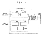
- FIG. 6 is a block diagram showing the detailed structure of a baseband using CDMA radio signals according to the third embodiment.
- a modulator 87 comprises the first modulator 81 which performs modulation such as PSK, QAM, and OFDM, and a diffuser 82.
- a demodulator 88 comprises a back diffuser 85, a first demodulator 84 which performs demodulation, and a rake receiver 86.
- the modulator 87 performs modulation such as PSK, QAM, and OFDM at the first modulator 81, and then performs diffusion at the diffuser 82 to produce a CDMA signal.
- the CDMA signal is sent to a transmitter-receiver by the transmission-reception interface 63 via the transmission line 68.
- the CDMA signal received by the transmitter-receiver is sent to the demodulator 88 by the transmission-reception interface 63 of the baseband 75 via the transmission line 68.
- the demodulator 88 performs back diffusion at the back diffuser 85, and then performs demodulation such as PSK, QAM, and OFDM at the first demodulator 84.
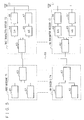
- the rake receiver 86 performs rake reception of CDMA signals not only from a transmitter-receiver in one cell but also from transmitter-receivers in a plurality of cells. As in the case where a mobile terminal is moving between cells, when a mobile terminal is in the coverage area of a plurality of cells, the rake receiver 86 performs rake reception of CDMA signals from the transmitter-receivers in the plurality of cells. For that reason, as shown in Fig 7, one baseband is in charge of plural adjacent cells to enlarge the cell area for which the baseband can perform rake reception.
- a transmitter-receiver 25 and a transmitter-receiver 26 digital-analog convert CDMA signals received from the mobile terminal 91, and then transmit the signals to baseband 75.
- the rake receiver 86 in the baseband 75 extracts multipath components 101 and 102 of the same data from each CDMA signal. From the multipath components 101 and 102, the high-level components (111, 112, 113) are extracted and synthesized. The synthesized signal is demodulated in the first demodulator 84, and a data signal is output.
- a plurality of radio base stations each comprise one baseband and a plurality of transmitter-receivers.
- the number of the basebands can be reduced.
- a plurality of basebands and a plurality of transmitter-receivers are connected with each other via one or more transmission lines. Thereby, the association between each baseband and the transmitter-receivers can be changed freely according to the situation.
- high-level multipath components received from a plurality of antennas are extracted and synthesized for rake reception, which can be performed without using handover even when a mobile terminal is moving between cells.
Landscapes
- Engineering & Computer Science (AREA)
- Computer Networks & Wireless Communication (AREA)
- Signal Processing (AREA)
- Mobile Radio Communication Systems (AREA)
Applications Claiming Priority (2)
| Application Number | Priority Date | Filing Date | Title |
|---|---|---|---|
| JP2003413270A JP2005175912A (ja) | 2003-12-11 | 2003-12-11 | セル型無線通信システム、セル型無線通信方法、レイク受信方法 |
| JP2003413270 | 2003-12-11 |
Publications (1)
| Publication Number | Publication Date |
|---|---|
| EP1542484A1 true EP1542484A1 (fr) | 2005-06-15 |
Family
ID=34510543
Family Applications (1)
| Application Number | Title | Priority Date | Filing Date |
|---|---|---|---|
| EP20040090486 Ceased EP1542484A1 (fr) | 2003-12-11 | 2004-12-10 | Système de communication radiocellulaire, procédé de communication radiocellulaire and procédé de réception Rake |
Country Status (4)
| Country | Link |
|---|---|
| US (1) | US7164707B2 (fr) |
| EP (1) | EP1542484A1 (fr) |
| JP (1) | JP2005175912A (fr) |
| CN (1) | CN100472979C (fr) |
Cited By (1)
| Publication number | Priority date | Publication date | Assignee | Title |
|---|---|---|---|---|
| EP1906579A3 (fr) * | 2006-09-29 | 2013-02-20 | Sharp Kabushiki Kaisha | Procédé et appareil pour la transmission de données et procédé et appareil pour la réception de données |
Families Citing this family (2)
| Publication number | Priority date | Publication date | Assignee | Title |
|---|---|---|---|---|
| US8107815B2 (en) * | 2008-03-31 | 2012-01-31 | Fujitsu Limited | System and method for communicating wireless data utilizing a passive optical network |
| CN111147151B (zh) * | 2019-05-06 | 2021-02-12 | 南京瑞贻电子科技有限公司 | 一种防追踪通信调制系统及通信方法 |
Citations (4)
| Publication number | Priority date | Publication date | Assignee | Title |
|---|---|---|---|---|
| US5887021A (en) * | 1996-09-23 | 1999-03-23 | Nokia Telecommunications Oy | Base station receiver and a method for receiving a signal |
| WO2001076277A2 (fr) * | 2000-04-05 | 2001-10-11 | Telefonaktiebolaget L M Ericsson (Publ) | Parametres de commande derives destines a la detection par synchronisation intermittente en telecommunications |
| US20010033600A1 (en) * | 2000-02-28 | 2001-10-25 | Golden Bridge Technology Inc. | Sectorized smart antenna system and method |
| US6577880B1 (en) * | 1999-07-19 | 2003-06-10 | Hitachi, Ltd. | Radio communication method and radio communication system |
Family Cites Families (4)
| Publication number | Priority date | Publication date | Assignee | Title |
|---|---|---|---|---|
| JP2858514B2 (ja) | 1992-11-16 | 1999-02-17 | 日本電信電話株式会社 | 無線通信システム |
| DE19918059C1 (de) * | 1999-04-21 | 2000-11-30 | Siemens Ag | Transceiver mit bidirektionalen internen Schnittstellenleitungen |
| CN1107358C (zh) * | 2000-02-24 | 2003-04-30 | 信息产业部电信科学技术研究院 | 分布式智能天线系统 |
| US20030086485A1 (en) * | 2001-11-08 | 2003-05-08 | John Lin | Master to multi-slave asynchronous transmit fifo |
-
2003
- 2003-12-11 JP JP2003413270A patent/JP2005175912A/ja active Pending
-
2004
- 2004-12-10 US US11/008,212 patent/US7164707B2/en not_active Expired - Fee Related
- 2004-12-10 EP EP20040090486 patent/EP1542484A1/fr not_active Ceased
- 2004-12-13 CN CNB2004101011391A patent/CN100472979C/zh not_active Expired - Fee Related
Patent Citations (4)
| Publication number | Priority date | Publication date | Assignee | Title |
|---|---|---|---|---|
| US5887021A (en) * | 1996-09-23 | 1999-03-23 | Nokia Telecommunications Oy | Base station receiver and a method for receiving a signal |
| US6577880B1 (en) * | 1999-07-19 | 2003-06-10 | Hitachi, Ltd. | Radio communication method and radio communication system |
| US20010033600A1 (en) * | 2000-02-28 | 2001-10-25 | Golden Bridge Technology Inc. | Sectorized smart antenna system and method |
| WO2001076277A2 (fr) * | 2000-04-05 | 2001-10-11 | Telefonaktiebolaget L M Ericsson (Publ) | Parametres de commande derives destines a la detection par synchronisation intermittente en telecommunications |
Cited By (1)
| Publication number | Priority date | Publication date | Assignee | Title |
|---|---|---|---|---|
| EP1906579A3 (fr) * | 2006-09-29 | 2013-02-20 | Sharp Kabushiki Kaisha | Procédé et appareil pour la transmission de données et procédé et appareil pour la réception de données |
Also Published As
| Publication number | Publication date |
|---|---|
| CN1627840A (zh) | 2005-06-15 |
| JP2005175912A (ja) | 2005-06-30 |
| CN100472979C (zh) | 2009-03-25 |
| US7164707B2 (en) | 2007-01-16 |
| US20050129102A1 (en) | 2005-06-16 |
Similar Documents
| Publication | Publication Date | Title |
|---|---|---|
| KR100911077B1 (ko) | 무선 통신 장치 및 무선 통신 방법 | |
| JP3348196B2 (ja) | 無線伝送システム | |
| CN100375550C (zh) | 一种基站系统 | |
| EP2175572B1 (fr) | Appareil et méthode pour transmision et réception | |
| FI105732B (fi) | Taajuuksien vaihdolla varustetuilla toistinasemilla toteutettu radioliikennejärjestelmä | |
| US7787854B2 (en) | Scalable distributed radio network | |
| US5818827A (en) | Radio communication device and radio communication method | |
| KR100719786B1 (ko) | 송신 다이버시티를 갖는 코드-분할, 다중-접속 기지국 | |
| US20040151503A1 (en) | Communication system having wireless transmission path and optical transmission path | |
| US20020025778A1 (en) | Integrated wireless local loop (WLL) and wireless local area network (WLAN) transceiver apparatus | |
| JPH1079722A (ja) | マルチコード符号分割多重アクセス受信器 | |
| US7394799B2 (en) | Apparatus and method using smart antenna in FDD wireless communication system | |
| EP2232942A1 (fr) | Communication asynchrone sur une interface radio publique commune (cpri) | |
| CN1113056A (zh) | 执行fdma传输的通信方法、设备和系统 | |
| EP2919553B1 (fr) | Station de base décentralisée et procédé de retour de signal, ainsi que son dispositif | |
| US6400750B1 (en) | Base station system and data transmission method of multicarrier CDMA/FDM hybrid system and mobile communication system using same | |
| JPH08181661A (ja) | 無線信号伝送装置 | |
| US7164707B2 (en) | Cellular radio communication system cellular radio communication method and rake reception method | |
| CN1252191A (zh) | 包括对称和非对称波形模式的移动卫星电话系统 | |
| US8115677B2 (en) | Transmitter and receiver-side processing of signals transmitted or received with a smart antenna | |
| JP2002191073A (ja) | 無線通信システム、及び無線通信システムにおける通信方法 | |
| JPH09270733A (ja) | スペクトラム拡散通信装置 | |
| CN1252192A (zh) | 具有tdma用户分隔的移动通信系统的基站和接收装置 | |
| KR100460425B1 (ko) | 이동 통신망에서의 스마트 안테나 시스템 | |
| JPH08167876A (ja) | 光伝送無線基地局及び受信ダイバーシチ方法 |
Legal Events
| Date | Code | Title | Description |
|---|---|---|---|
| PUAI | Public reference made under article 153(3) epc to a published international application that has entered the european phase |
Free format text: ORIGINAL CODE: 0009012 |
|
| AK | Designated contracting states |
Kind code of ref document: A1 Designated state(s): AT BE BG CH CY CZ DE DK EE ES FI FR GB GR HU IE IS IT LI LT LU MC NL PL PT RO SE SI SK TR |
|
| AX | Request for extension of the european patent |
Extension state: AL BA HR LV MK YU |
|
| 17P | Request for examination filed |
Effective date: 20050523 |
|
| AKX | Designation fees paid |
Designated state(s): DE FR GB |
|
| 17Q | First examination report despatched |
Effective date: 20050914 |
|
| STAA | Information on the status of an ep patent application or granted ep patent |
Free format text: STATUS: THE APPLICATION HAS BEEN REFUSED |
|
| 18R | Application refused |
Effective date: 20080329 |