EP1543377B1 - Minus power spectacle lens and methods of its production - Google Patents
Minus power spectacle lens and methods of its production Download PDFInfo
- Publication number
- EP1543377B1 EP1543377B1 EP03798248.5A EP03798248A EP1543377B1 EP 1543377 B1 EP1543377 B1 EP 1543377B1 EP 03798248 A EP03798248 A EP 03798248A EP 1543377 B1 EP1543377 B1 EP 1543377B1
- Authority
- EP
- European Patent Office
- Prior art keywords
- lens
- area
- spherical
- central
- aspheric
- Prior art date
- Legal status (The legal status is an assumption and is not a legal conclusion. Google has not performed a legal analysis and makes no representation as to the accuracy of the status listed.)
- Expired - Lifetime
Links
- 238000004519 manufacturing process Methods 0.000 title claims description 16
- 238000000034 method Methods 0.000 title description 11
- 238000012937 correction Methods 0.000 claims description 8
- 230000003287 optical effect Effects 0.000 claims description 5
- 230000003247 decreasing effect Effects 0.000 claims description 4
- 230000007704 transition Effects 0.000 claims description 4
- 238000005520 cutting process Methods 0.000 claims description 3
- 238000000465 moulding Methods 0.000 claims description 3
- 208000001491 myopia Diseases 0.000 claims description 3
- 230000004379 myopia Effects 0.000 claims description 2
- 230000010355 oscillation Effects 0.000 claims description 2
- 238000005498 polishing Methods 0.000 claims description 2
- 238000013461 design Methods 0.000 description 8
- 230000000694 effects Effects 0.000 description 8
- 239000000463 material Substances 0.000 description 7
- 230000002093 peripheral effect Effects 0.000 description 7
- 230000008901 benefit Effects 0.000 description 5
- 239000002537 cosmetic Substances 0.000 description 5
- 238000007688 edging Methods 0.000 description 4
- 230000008569 process Effects 0.000 description 4
- 230000009467 reduction Effects 0.000 description 4
- 230000004075 alteration Effects 0.000 description 3
- 239000000571 coke Substances 0.000 description 3
- 230000000875 corresponding effect Effects 0.000 description 3
- 230000004438 eyesight Effects 0.000 description 3
- 238000001746 injection moulding Methods 0.000 description 2
- 229910052500 inorganic mineral Inorganic materials 0.000 description 2
- 239000011707 mineral Substances 0.000 description 2
- 238000012545 processing Methods 0.000 description 2
- 238000003672 processing method Methods 0.000 description 2
- 239000003082 abrasive agent Substances 0.000 description 1
- 230000009471 action Effects 0.000 description 1
- 230000009286 beneficial effect Effects 0.000 description 1
- 230000002596 correlated effect Effects 0.000 description 1
- 230000003467 diminishing effect Effects 0.000 description 1
- 210000003128 head Anatomy 0.000 description 1
- 230000004886 head movement Effects 0.000 description 1
- 230000004402 high myopia Effects 0.000 description 1
- 238000005304 joining Methods 0.000 description 1
- 238000003754 machining Methods 0.000 description 1
- 230000007935 neutral effect Effects 0.000 description 1
- 230000036544 posture Effects 0.000 description 1
- 230000001179 pupillary effect Effects 0.000 description 1
- 238000011160 research Methods 0.000 description 1
- 239000007779 soft material Substances 0.000 description 1
- 229920001187 thermosetting polymer Polymers 0.000 description 1
- 238000009827 uniform distribution Methods 0.000 description 1
Images


Classifications
-
- G—PHYSICS
- G02—OPTICS
- G02C—SPECTACLES; SUNGLASSES OR GOGGLES INSOFAR AS THEY HAVE THE SAME FEATURES AS SPECTACLES; CONTACT LENSES
- G02C7/00—Optical parts
- G02C7/02—Lenses; Lens systems ; Methods of designing lenses
Definitions
- Subject of this invention is a myopic correcting lens for medium-to-strong to particularly strong prescriptions.
- the invention concerns a finished or semi-finished lens and the processing methods thereof.
- "Finished lens” means a lens with both surfaces finished, whereas “semi-finished” lens means a lens with one surface finished.
- the only method adopted has been that of reducing the size of the actual lens - that is the "lenticular" portion in which the prescribed power is provided.
- the remainder of the lens, the carrier provides no refractive correction but gives dimension to the lens for mounting.
- These are the so called “lenticular lenses”.
- the achieved reduction in weight and edge thickness is inversely proportional to the size of the lenticular portion of the lens.
- lighter and thinner, lenticular lenses remain cosmetically unattractive because the central portion, which makes the eyes look fairly smaller, is clearly discernible within each ring of the eyeglasses as is the portion joining it to the carrier.
- the wide surface of the carrier takes on a high plus power in sharp contrast to the high minus power of the centre.
- a "tunnel effect" is produced which badly distorts the portion of the face which is covered with the lens.
- the diameter of the actual optic area is insufficient to ensure viewing in all the natural directions of the gaze and forces the wearer to unnatural head postures in order to compensate for the limited freedom of movement of their eyes.
- the lens is a single-vision or multifocal eyeglass lens for medium-to-high to very high nearsightedness in plastic, mineral or other suitable material, lighter and thinner at the edges and ensuring a wide field of vision.
- It is cosmetically attractive, manufactured as a finished or semi-finished lens, featuring a spherical centre and an aspheric periphery, both asymmetrical to the lens optical centre (coinciding with the geometrical centre) and varying in width according to the power (central curvature of the lens) and the diameter (front width as viewed by an observer facing the eyeglass wearer) of the lens itself.
- the invention also covers all the procedures involved in the manufacturing of the lens, based on both non industrial and CNC processing and moulding and/or injection moulding techniques.
- the reference tables 1/5, 2/5, 3/5, 4/5 and 5/5 provide a lens manufacturing plan which is to be regarded as an example and is by no way restrictive.
- Fig. 1 compares three projections of the lens design (1) to the projections of an ordinary plano-concave lens (100) with a constant curve.
- the minus lens is subdivided into two areas ( Fig. 1a ).
- a centrally spherical area (2) is encompassed within the ZZ' diameter, which defines the refractive correction of the lens, and equals 70% of DD' in width. This area is wider in large diameter and medium-to-low myopic power lenses and smaller in small diameter and medium-to-high to very high myopic power lenses (small radiuses of curvature).
- Tangential to it is an aspheric area, which consists of a paracentral area (3) encompassing the spherical area (2), with a diameter equal to 10% of DD'.
- a peripheral area (4) encloses the paracentral area; it is tangential to the central, spherical area and stretches down to the lens edge. This is the flattest area which allows for the reduced lens mass and thickness.
- the three areas are adequately connected in space, the intersection between a plane perpendicular to that drawn by diameters DD' and AA' and the back surface of the lens being a polynomial curve which interpolates a set of accurately calculated points.
- the end surface profile of the lens (1) results from the summation of a series of portions of spherical surfaces.
- the first surface results from the intersection between the initial flat semi-finished material and a sphere with a radius R, the centre of which lies on the straight line passing through C and is perpendicular to the base of the semi-finished lens.
- the obtained profile is identical to that of a lens (100) ( Fig. 1c to the left) with a constant curvature, an edge thickness S and a central thickness Sc.
- the aspheric area of the lens is designed so that its axis is inclined with respect to the axis of the central area of an appropriate angle.
- the second and the following cuttings are made through a generally spherical surface Bn, the centre of which (Cn) lies along the half-line originating at C and having an inclination angle the radius Rn of which is correlated to the power of the peripheral area ( ⁇ n), which is considered as constant.
- the centre Cn is extrapolated from the thickness S1 at the lens edge, corresponding to the extreme D of the reference diameter.
- S1 is a predetermined fraction of S. It follows that the thickness S2 corresponds to D'. For instance, if S1 equals 60% of S, S2 will be about 75% of S ( Fig. 1b ).
- n can be regarded as a design constant or a parameter to be increased, should the number of repetitions be insufficient to yield the required accuracy, or decreased, should the obtained accuracy exceed that of the tool used to cut the lens, be it a non-industrial or an industrial tool (CNC cutting machine).
- the concurrent action of the inclination of the axis of the aspheric periphery of the lens with respect to the axis of the centrally spherical area and the radial reduction in power towards the external edge of the lens contribute to making the lens surface asymmetrical with respect to AA' and causing a simultaneous, variable reduction in the thickness of the peripheral area.
- a further consequence of the inclination of the axis of the peripheral area is its varying width along DD'. It is maximum close to the minimum peripheral thickness S 1 and minimum at the maximum peripheral thickness S2.
- the eccentricity of the peripheral area produces a gradual decrease in the central power of the lens with a subsequent reduction in the thickness at the edges.
- the advantage is that the points which are immediately adjacent to the central area (paracentral area) have a refractive correction close to that of the central area.
- the thickness at the edges, S 1 and S2 ( Fig. 1b ), is less than that of a 100 plano-concave lens having the same diameter, central thickness, refractive index and power.
- both the spherical and the aspheric areas are asymmetrical with respect to the centre C.
- the centrally spherical area ZZ' ( Fig.
- the only one which retains the profile of the 100 plano-concave lens stretches more to the left (CZ' portion) than to the right (CZ portion).
- the aspheric periphery is narrower to the left (D'Z' portion) than to the right (DZ portion).
- the surface curve variation which remains negative at all points is more marked along the DZ portion than along the D'Z' portion.
- the same power drop is reported along two segments (DZ and D'Z') and at two different heights, thus originating absolutely different profiles.
- section 1c the end profile of the lens has been drawn, showing the amount of removed stock and the mitigated "coke bottle” effect when compared to the constant curvature lens (100).
- the angle ⁇ ' of the lens periphery (1) is smaller than the angle ⁇ of any ordinary lens (100) - in which the prismatic effect causes the reflections of edging to converge towards the back side of the lens - and the reflections of the edging of the innovative lens are caused to converge outside the lens.
- the lens (1) is thus free of the "coke bottle” effect which is typical of any minus power lens.
- Fig. 2 documents the benefits of the asymmetrical surface of this lens design which complies, during mounting, with the interpupillary distance of wearers with a wide ( Fig. 2a ) or short distance ( Fig. 2b ).
- Being PP' the interpupillary distance in the case of a wide interpupillary distance ( Fig. 2a ), it is advisable to cut the lens in such a way that, when the optical/geometric centre overlaps the pupillary centre P or P', the wider aspheric periphery coincides with the temple of the wearer and the narrower section with the nasal portion.
- a short interpupillary distance Fig.
- the central area (with a constant power) and the paracentral area (with a power close to the central one) cover most of the width of the outline of the eyeglasses and the wearer benefits from vision acuity in all the directions of the gaze, without having to resort to unnatural head movements, whereas the periphery, with a more marked power drop, lies at the extreme temple periphery of the eyeglasses, thereby diminishing the thickness and weight of the lens as well as the spherical aberration, which is typical of lenses with a small radius of curvature and high edge thickness, and nullifying the reflections of the lens edging.
- the aspheric surface noticeably improves the lens.
- the power drop beside reducing the spherical aberration, also lessens the shrinking effect which is produced by the periphery, thus preventing any distortion of the face of the wearer covered with eyeglasses, as viewed from the outside.
- Fig. 2 a and Fig. 2b are but general sketches. According to the prescribed power, the actual interpupillary distance, the selected frame and the desired cosmetic effect, the best diameter, the best aspheric shape of the lens and the portion of the periphery with a different power drop to be located at the temple can be selected.
- the lens can be manufactured as a "semi-finished” or “finished” lens.
- the “semi-finished” lens is obtained from a blank (unfinished on both sides) which is finished on the back surface alone with a precise dioptric power. From this semi-finished lens a wide range of prescribed dioptric powers can be derived by finishing the front side in a spherical or toric fashion.
- the finished lens is obtained from a semi-finished lens, with the front side already conventionally finished with a given dioptric power.
- the back side is finished to give the lens the prescribed power.
- FIG. 3a shows a projection of the back surface of the lens onto the plane ⁇ 1 passing through the reference diameter (DD') and perpendicular to the axis (AA'), highlighting the difference in edge thickness (S 1 and S2) and profile and the general asymmetry between the right side and the left side with respect to the axis AA', perpendicular to the plane of the drawing.
- Fig. 3b shows a projection of the back surface of the lens onto the plane ⁇ 2 passing through the axis AA' and perpendicular to the diameter DD'.
- Fig. 3c shows a projection of the back surface of the lens onto the plane ⁇ 3 with a 25° rotation with respect to ⁇ 1 and a 10° inclination towards the viewer, so as to display the surface as a whole.
- Finished lenses for the most common power intervals and "semi-finished” lenses can be industrially produced for moulding or, in the case of thermoset plastic materials, for injection moulding in ready-made moulds. Should the invention be industrially manufactured, reduced production costs would go hand in hand with accrued eyeglass customisation.
- the semi-finished lens would have a front flat surface on which the reference diameter DD', the geometrical centre C and a central portion KK', having a width equal to a predetermined fraction of DD', would be temporarily marked.
- KK' should preferably ⁇ 65% DD' ( Fig. 4a ).
- the marking of KK' helps manufacture the aspheric periphery of the lens.
- Fig. 4b illustrates the first step, the so called "rough grinding" of the lens.
- the axis Ap of the principal base Bp is maintained inclined with respect to the axis As of the secondary base Bs at a corresponding angle ⁇ .
- a "prismatic ring" or wedge ⁇ is inserted between the lens and the generator chuck and oriented along the reference diameter DD', with its base towards D. The wedge gives asymmetry to the final surface of the lens.
- Fig. 4c shows
- the base Bs varies in width.
- the central portion of Bp is asymmetrical to the geometrical centre of the lens.
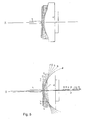
- lapping ( Fig. 5 ) and it draws the ultimate contour of the lens back side.
- a conventional lapping machine can be used to this end. After lapping both surfaces (Bp and Bs) with the appropriate spherical tools, having the same bases (Bp and Bs), lapping proceeds so that the tools with bases Bn, ranging between Bp and Bs, cut the cusps in between the various portions of the spherical surfaces which are generated at every stroke. A gradual transition from the lens edge to K is thus obtained, temporarily marked at the centre, with a satisfactory spatial connection.
- the calculations for selecting Bn tools and the amount of stock to be removed are referred to the area of the lens with thickness S1.
- a rod P through a ball-and-socket joint, ensures uniform distribution of pressure and freedom of rotation and transmits an oscillation to the lens which is kept flush with the tool (Bn).
- the lens self-centres onto the temporary chamfer resulting from the intersection of the previously used bases and takes on a varying inclination ⁇ n ⁇ ⁇ .
- every newly generated surface portion is not concentric, but variously connected at every point, thus originating an overall aspheric surface, which is asymmetrical to the optical/geometrical centre of the lens.
- Fig. 5a It is worth underscoring that only some surfaces with major curvature differences have been highlighted in Fig. 5a .
- the number of required tools will vary with the desired accuracy, function and cosmetics of the lens.
- an optional tool Bj can be used in a resistant but soft material ( Fig. 5b ), with a mean curvature with respect to the previously used tools. Given the type of material in use, the tool will take on the same outline of the periphery of the lens, as expected.
Landscapes
- Health & Medical Sciences (AREA)
- Ophthalmology & Optometry (AREA)
- Physics & Mathematics (AREA)
- General Health & Medical Sciences (AREA)
- General Physics & Mathematics (AREA)
- Optics & Photonics (AREA)
- Eyeglasses (AREA)
Applications Claiming Priority (3)
| Application Number | Priority Date | Filing Date | Title |
|---|---|---|---|
| ITBA20020033 | 2002-09-24 | ||
| ITBA20020033 ITBA20020033A1 (it) | 2002-09-24 | 2002-09-24 | Lente oftalmica innovativa per miopia e suoi metodi di realizzazione. |
| PCT/IB2003/001242 WO2004029694A1 (en) | 2002-09-24 | 2003-03-31 | Minus power spectacle lens and methods of its production |
Publications (2)
| Publication Number | Publication Date |
|---|---|
| EP1543377A1 EP1543377A1 (en) | 2005-06-22 |
| EP1543377B1 true EP1543377B1 (en) | 2014-07-23 |
Family
ID=32040242
Family Applications (1)
| Application Number | Title | Priority Date | Filing Date |
|---|---|---|---|
| EP03798248.5A Expired - Lifetime EP1543377B1 (en) | 2002-09-24 | 2003-03-31 | Minus power spectacle lens and methods of its production |
Country Status (6)
| Country | Link |
|---|---|
| EP (1) | EP1543377B1 (da) |
| AU (1) | AU2003215848A1 (da) |
| DK (1) | DK1543377T3 (da) |
| ES (1) | ES2509465T3 (da) |
| IT (1) | ITBA20020033A1 (da) |
| WO (1) | WO2004029694A1 (da) |
Families Citing this family (4)
| Publication number | Priority date | Publication date | Assignee | Title |
|---|---|---|---|---|
| JP6758295B2 (ja) * | 2014-12-31 | 2020-09-23 | エシロール エンテルナショナル | 眼鏡フレームに枠入れされるための眼鏡眼用レンズ |
| US10782541B2 (en) | 2015-11-23 | 2020-09-22 | Carl Zeiss Vision International Gmbh | Method for designing a lens shape and spectacle lens |
| KR20210124320A (ko) * | 2019-02-08 | 2021-10-14 | 도카이 옵티컬 컴퍼니 리미티드 | 마이너스 강도의 안경용 전구체 렌즈, 안경용 렌즈 및 마이너스 강도의 안경용 전구체 렌즈의 가공방법 |
| WO2025133357A1 (en) * | 2023-12-22 | 2025-06-26 | Essilor International | Ophthalmic lens with modified peripheral curvature variation |
Family Cites Families (4)
| Publication number | Priority date | Publication date | Assignee | Title |
|---|---|---|---|---|
| GB550644A (en) * | 1941-07-09 | 1943-01-18 | Philips Nv | Improvements in or relating to optical elements |
| US4008031A (en) * | 1975-08-22 | 1977-02-15 | Weber Hermann P | Apparatus for injection molding lenses |
| DE3229577A1 (de) * | 1982-08-07 | 1984-02-09 | Fa. Carl Zeiss, 7920 Heidenheim | Brillenlinse fuer stark fehlsichtige |
| NL8502142A (nl) * | 1985-07-26 | 1987-02-16 | Optimed Nv | Werkwijze voor het vervaardigen van een brilleglas voor bijzienden. |
-
2002
- 2002-09-24 IT ITBA20020033 patent/ITBA20020033A1/it unknown
-
2003
- 2003-03-31 WO PCT/IB2003/001242 patent/WO2004029694A1/en not_active Ceased
- 2003-03-31 AU AU2003215848A patent/AU2003215848A1/en not_active Abandoned
- 2003-03-31 EP EP03798248.5A patent/EP1543377B1/en not_active Expired - Lifetime
- 2003-03-31 ES ES03798248.5T patent/ES2509465T3/es not_active Expired - Lifetime
- 2003-03-31 DK DK03798248.5T patent/DK1543377T3/da active
Also Published As
| Publication number | Publication date |
|---|---|
| AU2003215848A1 (en) | 2004-04-19 |
| ITBA20020033A1 (it) | 2004-03-25 |
| ES2509465T3 (es) | 2014-10-17 |
| DK1543377T3 (da) | 2014-09-29 |
| WO2004029694A1 (en) | 2004-04-08 |
| EP1543377A1 (en) | 2005-06-22 |
Similar Documents
| Publication | Publication Date | Title |
|---|---|---|
| EP4127825B1 (en) | Lens element | |
| US3960442A (en) | Ophthalmic lens series | |
| EP0900403B1 (en) | Improved single vision lenses | |
| US8950858B2 (en) | System and method of surfacing a lens, such as a lens for use with eyeglasses | |
| US7029116B2 (en) | Innovative minus power lens and processing methods thereof | |
| JP2013238881A (ja) | 球面形の前面と多焦点裏面を有する眼鏡レンズの製造方法 | |
| US7101042B2 (en) | Multifocal contact lens | |
| US8678586B2 (en) | Method for producing cost-optimized spectacle lenses with especially advantageous properties for the user | |
| CA2332330C (en) | Contact lenses with contoured edges | |
| CN115561920A (zh) | 用于设计镜片形状和眼镜镜片的方法 | |
| US9164294B2 (en) | Method for the manufacture of cost-optimized spectacle lenses | |
| US3797922A (en) | Azygous ophthalmic lens and spectacles for correcting presbyopia | |
| EP1543377B1 (en) | Minus power spectacle lens and methods of its production | |
| US10928655B2 (en) | Reduced distortion spectacle lens | |
| AU2019428531B2 (en) | Negative-strength eyeglass lens blank, eyeglass lens, and method of processing negative-strength eyeglass lens blank | |
| US3867798A (en) | Method of producing variable profile bi-focal lens | |
| Meister et al. | Principles of atoric lens design | |
| US10168548B2 (en) | Optical lens blank, a blank assortment and a method for the production of lenses | |
| US1969622A (en) | Ophthalmic lens | |
| JP2004094004A (ja) | マルチフォーカルレンズ | |
| HK1037031A (en) | Contact lenses with contoured edges | |
| HK1083127A (en) | Multifocal contact lens |
Legal Events
| Date | Code | Title | Description |
|---|---|---|---|
| PUAI | Public reference made under article 153(3) epc to a published international application that has entered the european phase |
Free format text: ORIGINAL CODE: 0009012 |
|
| 17P | Request for examination filed |
Effective date: 20050207 |
|
| AK | Designated contracting states |
Kind code of ref document: A1 Designated state(s): AT BE BG CH CY CZ DE DK EE ES FI FR GB GR HU IE IT LI LU MC NL PT RO SE SI SK TR |
|
| AX | Request for extension of the european patent |
Extension state: AL |
|
| DAX | Request for extension of the european patent (deleted) | ||
| REG | Reference to a national code |
Ref country code: HK Ref legal event code: DE Ref document number: 1082805 Country of ref document: HK |
|
| 17Q | First examination report despatched |
Effective date: 20090223 |
|
| REG | Reference to a national code |
Ref country code: HK Ref legal event code: WD Ref document number: 1082805 Country of ref document: HK |
|
| GRAP | Despatch of communication of intention to grant a patent |
Free format text: ORIGINAL CODE: EPIDOSNIGR1 |
|
| INTG | Intention to grant announced |
Effective date: 20140210 |
|
| GRAS | Grant fee paid |
Free format text: ORIGINAL CODE: EPIDOSNIGR3 |
|
| GRAA | (expected) grant |
Free format text: ORIGINAL CODE: 0009210 |
|
| AK | Designated contracting states |
Kind code of ref document: B1 Designated state(s): AT BE BG CH CY CZ DE DK EE ES FI FR GB GR HU IE IT LI LU MC NL PT RO SE SI SK TR |
|
| REG | Reference to a national code |
Ref country code: GB Ref legal event code: FG4D |
|
| REG | Reference to a national code |
Ref country code: CH Ref legal event code: EP |
|
| REG | Reference to a national code |
Ref country code: IE Ref legal event code: FG4D |
|
| REG | Reference to a national code |
Ref country code: AT Ref legal event code: REF Ref document number: 679170 Country of ref document: AT Kind code of ref document: T Effective date: 20140815 |
|
| REG | Reference to a national code |
Ref country code: DE Ref legal event code: R096 Ref document number: 60346541 Country of ref document: DE Effective date: 20140904 |
|
| REG | Reference to a national code |
Ref country code: DK Ref legal event code: T3 Effective date: 20140922 |
|
| REG | Reference to a national code |
Ref country code: ES Ref legal event code: FG2A Ref document number: 2509465 Country of ref document: ES Kind code of ref document: T3 Effective date: 20141017 |
|
| REG | Reference to a national code |
Ref country code: NL Ref legal event code: VDEP Effective date: 20140723 |
|
| PG25 | Lapsed in a contracting state [announced via postgrant information from national office to epo] |
Ref country code: BG Free format text: LAPSE BECAUSE OF FAILURE TO SUBMIT A TRANSLATION OF THE DESCRIPTION OR TO PAY THE FEE WITHIN THE PRESCRIBED TIME-LIMIT Effective date: 20141023 Ref country code: FI Free format text: LAPSE BECAUSE OF FAILURE TO SUBMIT A TRANSLATION OF THE DESCRIPTION OR TO PAY THE FEE WITHIN THE PRESCRIBED TIME-LIMIT Effective date: 20140723 Ref country code: SE Free format text: LAPSE BECAUSE OF FAILURE TO SUBMIT A TRANSLATION OF THE DESCRIPTION OR TO PAY THE FEE WITHIN THE PRESCRIBED TIME-LIMIT Effective date: 20140723 Ref country code: GR Free format text: LAPSE BECAUSE OF FAILURE TO SUBMIT A TRANSLATION OF THE DESCRIPTION OR TO PAY THE FEE WITHIN THE PRESCRIBED TIME-LIMIT Effective date: 20141024 Ref country code: PT Free format text: LAPSE BECAUSE OF FAILURE TO SUBMIT A TRANSLATION OF THE DESCRIPTION OR TO PAY THE FEE WITHIN THE PRESCRIBED TIME-LIMIT Effective date: 20141124 |
|
| PG25 | Lapsed in a contracting state [announced via postgrant information from national office to epo] |
Ref country code: CY Free format text: LAPSE BECAUSE OF FAILURE TO SUBMIT A TRANSLATION OF THE DESCRIPTION OR TO PAY THE FEE WITHIN THE PRESCRIBED TIME-LIMIT Effective date: 20140723 Ref country code: NL Free format text: LAPSE BECAUSE OF FAILURE TO SUBMIT A TRANSLATION OF THE DESCRIPTION OR TO PAY THE FEE WITHIN THE PRESCRIBED TIME-LIMIT Effective date: 20140723 |
|
| REG | Reference to a national code |
Ref country code: FR Ref legal event code: PLFP Year of fee payment: 13 |
|
| REG | Reference to a national code |
Ref country code: DE Ref legal event code: R097 Ref document number: 60346541 Country of ref document: DE |
|
| PG25 | Lapsed in a contracting state [announced via postgrant information from national office to epo] |
Ref country code: RO Free format text: LAPSE BECAUSE OF FAILURE TO SUBMIT A TRANSLATION OF THE DESCRIPTION OR TO PAY THE FEE WITHIN THE PRESCRIBED TIME-LIMIT Effective date: 20140723 Ref country code: SK Free format text: LAPSE BECAUSE OF FAILURE TO SUBMIT A TRANSLATION OF THE DESCRIPTION OR TO PAY THE FEE WITHIN THE PRESCRIBED TIME-LIMIT Effective date: 20140723 Ref country code: IT Free format text: LAPSE BECAUSE OF FAILURE TO SUBMIT A TRANSLATION OF THE DESCRIPTION OR TO PAY THE FEE WITHIN THE PRESCRIBED TIME-LIMIT Effective date: 20140723 Ref country code: EE Free format text: LAPSE BECAUSE OF FAILURE TO SUBMIT A TRANSLATION OF THE DESCRIPTION OR TO PAY THE FEE WITHIN THE PRESCRIBED TIME-LIMIT Effective date: 20140723 Ref country code: CZ Free format text: LAPSE BECAUSE OF FAILURE TO SUBMIT A TRANSLATION OF THE DESCRIPTION OR TO PAY THE FEE WITHIN THE PRESCRIBED TIME-LIMIT Effective date: 20140723 |
|
| PLBE | No opposition filed within time limit |
Free format text: ORIGINAL CODE: 0009261 |
|
| STAA | Information on the status of an ep patent application or granted ep patent |
Free format text: STATUS: NO OPPOSITION FILED WITHIN TIME LIMIT |
|
| 26N | No opposition filed |
Effective date: 20150424 |
|
| PG25 | Lapsed in a contracting state [announced via postgrant information from national office to epo] |
Ref country code: SI Free format text: LAPSE BECAUSE OF FAILURE TO SUBMIT A TRANSLATION OF THE DESCRIPTION OR TO PAY THE FEE WITHIN THE PRESCRIBED TIME-LIMIT Effective date: 20140723 |
|
| REG | Reference to a national code |
Ref country code: FR Ref legal event code: PLFP Year of fee payment: 14 |
|
| PGFP | Annual fee paid to national office [announced via postgrant information from national office to epo] |
Ref country code: AT Payment date: 20160323 Year of fee payment: 14 |
|
| REG | Reference to a national code |
Ref country code: FR Ref legal event code: PLFP Year of fee payment: 15 |
|
| PG25 | Lapsed in a contracting state [announced via postgrant information from national office to epo] |
Ref country code: HU Free format text: LAPSE BECAUSE OF FAILURE TO SUBMIT A TRANSLATION OF THE DESCRIPTION OR TO PAY THE FEE WITHIN THE PRESCRIBED TIME-LIMIT; INVALID AB INITIO Effective date: 20030331 |
|
| PG25 | Lapsed in a contracting state [announced via postgrant information from national office to epo] |
Ref country code: TR Free format text: LAPSE BECAUSE OF FAILURE TO SUBMIT A TRANSLATION OF THE DESCRIPTION OR TO PAY THE FEE WITHIN THE PRESCRIBED TIME-LIMIT Effective date: 20140723 |
|
| REG | Reference to a national code |
Ref country code: AT Ref legal event code: MM01 Ref document number: 679170 Country of ref document: AT Kind code of ref document: T Effective date: 20170331 |
|
| PG25 | Lapsed in a contracting state [announced via postgrant information from national office to epo] |
Ref country code: AT Free format text: LAPSE BECAUSE OF NON-PAYMENT OF DUE FEES Effective date: 20170331 |
|
| REG | Reference to a national code |
Ref country code: FR Ref legal event code: PLFP Year of fee payment: 16 |
|
| PGFP | Annual fee paid to national office [announced via postgrant information from national office to epo] |
Ref country code: IE Payment date: 20200211 Year of fee payment: 18 Ref country code: GB Payment date: 20200211 Year of fee payment: 18 Ref country code: DE Payment date: 20200220 Year of fee payment: 18 Ref country code: MC Payment date: 20200221 Year of fee payment: 18 Ref country code: DK Payment date: 20200224 Year of fee payment: 18 |
|
| PGFP | Annual fee paid to national office [announced via postgrant information from national office to epo] |
Ref country code: LU Payment date: 20200220 Year of fee payment: 18 Ref country code: CH Payment date: 20200319 Year of fee payment: 18 Ref country code: BE Payment date: 20200318 Year of fee payment: 18 |
|
| PGFP | Annual fee paid to national office [announced via postgrant information from national office to epo] |
Ref country code: FR Payment date: 20200313 Year of fee payment: 18 |
|
| PGFP | Annual fee paid to national office [announced via postgrant information from national office to epo] |
Ref country code: ES Payment date: 20200401 Year of fee payment: 18 |
|
| REG | Reference to a national code |
Ref country code: DE Ref legal event code: R119 Ref document number: 60346541 Country of ref document: DE |
|
| PG25 | Lapsed in a contracting state [announced via postgrant information from national office to epo] |
Ref country code: MC Free format text: LAPSE BECAUSE OF NON-PAYMENT OF DUE FEES Effective date: 20210331 |
|
| REG | Reference to a national code |
Ref country code: CH Ref legal event code: PL |
|
| REG | Reference to a national code |
Ref country code: DK Ref legal event code: EBP Effective date: 20210331 |
|
| GBPC | Gb: european patent ceased through non-payment of renewal fee |
Effective date: 20210331 |
|
| REG | Reference to a national code |
Ref country code: BE Ref legal event code: MM Effective date: 20210331 |
|
| PG25 | Lapsed in a contracting state [announced via postgrant information from national office to epo] |
Ref country code: IE Free format text: LAPSE BECAUSE OF NON-PAYMENT OF DUE FEES Effective date: 20210331 Ref country code: GB Free format text: LAPSE BECAUSE OF NON-PAYMENT OF DUE FEES Effective date: 20210331 Ref country code: FR Free format text: LAPSE BECAUSE OF NON-PAYMENT OF DUE FEES Effective date: 20210331 Ref country code: DE Free format text: LAPSE BECAUSE OF NON-PAYMENT OF DUE FEES Effective date: 20211001 Ref country code: LI Free format text: LAPSE BECAUSE OF NON-PAYMENT OF DUE FEES Effective date: 20210331 Ref country code: LU Free format text: LAPSE BECAUSE OF NON-PAYMENT OF DUE FEES Effective date: 20210331 Ref country code: CH Free format text: LAPSE BECAUSE OF NON-PAYMENT OF DUE FEES Effective date: 20210331 |
|
| PG25 | Lapsed in a contracting state [announced via postgrant information from national office to epo] |
Ref country code: DK Free format text: LAPSE BECAUSE OF NON-PAYMENT OF DUE FEES Effective date: 20210331 |
|
| REG | Reference to a national code |
Ref country code: ES Ref legal event code: FD2A Effective date: 20220524 |
|
| PG25 | Lapsed in a contracting state [announced via postgrant information from national office to epo] |
Ref country code: ES Free format text: LAPSE BECAUSE OF NON-PAYMENT OF DUE FEES Effective date: 20210401 Ref country code: BE Free format text: LAPSE BECAUSE OF NON-PAYMENT OF DUE FEES Effective date: 20210331 |