EP1543743A1 - Zusammenlegbarer Tisch - Google Patents
Zusammenlegbarer Tisch Download PDFInfo
- Publication number
- EP1543743A1 EP1543743A1 EP04029970A EP04029970A EP1543743A1 EP 1543743 A1 EP1543743 A1 EP 1543743A1 EP 04029970 A EP04029970 A EP 04029970A EP 04029970 A EP04029970 A EP 04029970A EP 1543743 A1 EP1543743 A1 EP 1543743A1
- Authority
- EP
- European Patent Office
- Prior art keywords
- bearing
- table surface
- collapsible
- leg
- bearing body
- Prior art date
- Legal status (The legal status is an assumption and is not a legal conclusion. Google has not performed a legal analysis and makes no representation as to the accuracy of the status listed.)
- Granted
Links
- 229920001971 elastomer Polymers 0.000 claims description 7
- 239000005060 rubber Substances 0.000 claims description 7
- 239000013013 elastic material Substances 0.000 claims description 3
- 239000000463 material Substances 0.000 abstract description 10
- 239000011324 bead Substances 0.000 description 11
- 238000010276 construction Methods 0.000 description 8
- 230000007246 mechanism Effects 0.000 description 4
- 239000002184 metal Substances 0.000 description 3
- 229910052751 metal Inorganic materials 0.000 description 3
- 230000006641 stabilisation Effects 0.000 description 3
- 238000011105 stabilization Methods 0.000 description 3
- 239000004744 fabric Substances 0.000 description 2
- 238000000034 method Methods 0.000 description 2
- 235000021178 picnic Nutrition 0.000 description 2
- 239000004033 plastic Substances 0.000 description 2
- 229920003023 plastic Polymers 0.000 description 2
- 229920001296 polysiloxane Polymers 0.000 description 2
- 230000002269 spontaneous effect Effects 0.000 description 2
- 241000446313 Lamella Species 0.000 description 1
- 239000011111 cardboard Substances 0.000 description 1
- 238000003780 insertion Methods 0.000 description 1
- 230000037431 insertion Effects 0.000 description 1
- 239000003562 lightweight material Substances 0.000 description 1
- 238000004519 manufacturing process Methods 0.000 description 1
- 150000002739 metals Chemical class 0.000 description 1
- 239000000123 paper Substances 0.000 description 1
- 230000002093 peripheral effect Effects 0.000 description 1
- 229920005989 resin Polymers 0.000 description 1
- 239000011347 resin Substances 0.000 description 1
- 238000007789 sealing Methods 0.000 description 1
- 239000002689 soil Substances 0.000 description 1
- 239000011343 solid material Substances 0.000 description 1
- 239000002023 wood Substances 0.000 description 1
Images


Classifications
-
- A—HUMAN NECESSITIES
- A47—FURNITURE; DOMESTIC ARTICLES OR APPLIANCES; COFFEE MILLS; SPICE MILLS; SUCTION CLEANERS IN GENERAL
- A47B—TABLES; DESKS; OFFICE FURNITURE; CABINETS; DRAWERS; GENERAL DETAILS OF FURNITURE
- A47B3/00—Folding or stowable tables
- A47B3/12—Stowable tables with detachable top leaves
-
- A—HUMAN NECESSITIES
- A47—FURNITURE; DOMESTIC ARTICLES OR APPLIANCES; COFFEE MILLS; SPICE MILLS; SUCTION CLEANERS IN GENERAL
- A47B—TABLES; DESKS; OFFICE FURNITURE; CABINETS; DRAWERS; GENERAL DETAILS OF FURNITURE
- A47B13/00—Details of tables or desks
- A47B13/02—Underframes
- A47B13/023—Underframes with a central column
-
- A—HUMAN NECESSITIES
- A47—FURNITURE; DOMESTIC ARTICLES OR APPLIANCES; COFFEE MILLS; SPICE MILLS; SUCTION CLEANERS IN GENERAL
- A47B—TABLES; DESKS; OFFICE FURNITURE; CABINETS; DRAWERS; GENERAL DETAILS OF FURNITURE
- A47B3/00—Folding or stowable tables
- A47B3/04—Folding or stowable tables with flexible roll-tops
-
- A—HUMAN NECESSITIES
- A47—FURNITURE; DOMESTIC ARTICLES OR APPLIANCES; COFFEE MILLS; SPICE MILLS; SUCTION CLEANERS IN GENERAL
- A47B—TABLES; DESKS; OFFICE FURNITURE; CABINETS; DRAWERS; GENERAL DETAILS OF FURNITURE
- A47B3/00—Folding or stowable tables
- A47B3/10—Travelling or trunk tables
-
- A—HUMAN NECESSITIES
- A45—HAND OR TRAVELLING ARTICLES
- A45B—WALKING STICKS; UMBRELLAS; LADIES' OR LIKE FANS
- A45B19/00—Special folding or telescoping of umbrellas
Definitions
- the invention relates to a collapsible table with a Table surface and a frame supporting the table surface.
- DE-OS 199 02 223 A1 is a collapsible table become known, in which the table top of a variety hinged coupled side by side Table leaves is made, eliminating the table top Roller shutter-like is collapsible. Design required this table is very rigid and stable tabletop, which means these become heavy and limited collapsibility is.
- JP-AA 2000 135 120 is a table for outdoor use become known, the collapsible leg construction has on which one of narrow rigid panels existing placed in one direction rollable plate can be.
- US-A 5,425,315 shows a folding table of use a mechanism known by umbrellas ago suggests. These are centrally hinged rigid slats, which form the surface of the table, from below through a spanned by a complicated mechanism Supported frame. Because of the high dead weight and big Forces in individual joints, this design is only in metal possible, making them difficult again and only limited can be used.
- the invention is therefore the object of an opposite known constructions improved collapsible To provide table, in particular by the construction requires less expensive materials used are.
- the table surface substantially from a flat flexible support layer is formed, wherein the support layer by at least three folding arms is worn, with the folding arms vertically pivotable to the table surface on the frame in one Swivel bearings are articulated.
- the invention proposes the rigid tabletops or in Single segments of divided rigid table tops to get around by a flexible support layer is clamped by itself forms a table surface.
- This makes light and flexible Materials for use possible, creating a very light and small collapsible construction is made possible.
- the table is easy to fold and save space Foldable, easy to carry and easy and fast to build according to opportunity and need.
- the table surface is to be selected from a material that is such that it is flexible and stabilizable and owns the properties, folding, folding and to allow the stowing especially in the table rail / foot.
- a preferred embodiment of the invention provides that the pivot bearings ring around the perpendicular bisector of the Table surface are arranged. This is a symmetrical Swivel movement possible for all folding arms.
- An advantageous embodiment of the invention proposes that the pivot bearings in a parallel to the table surface Level are arranged.
- the pivot bearings are formed on a bearing body, which is fastened to a support body of the frame.
- the folding arms are provided on the bearing body supports for the folding arms, the folding arms with completely unfolded pivoting, in particular 90 ° against the perpendicular bisector of the table surface, support.
- the supports are according to a further advantageous embodiment the invention annular around the perpendicular bisector Table surface arranged, these being in a larger radius are arranged as the pivot bearings. This will be simplest Means optimal support of the folding arms reached. Mechanisms or materials that absorb large forces can not be needed.
- bearing axes of the pivot bearing by a Bearing ring made of an elastic material, in particular rubber, are formed. Due to this inexpensive available standing means are also material fluctuations in the production balanced and the table is flexible against slight tilting and can compensate for force peaks.
- the folding arms are facing on their support layer Site at least in places firmly connected to this are.
- the base course is always pulled smooth and forms an optimal table surface when the table is opened is.
- An advantageous embodiment of the invention provides that the support layer at the puncture point of the perpendicular bisector of Table surface is connected to the bearing body.
- the folding arms on the bearing body in one guided perpendicular to the table surface arranged slot guide.
- the folding arms are always defined by the unfolded to the folded position, without, that they can tilt or jump out of the camp.
- the forced guidance is designed so that they an assembly and disassembly by reversing the curved path allows.
- the frame an elongated hollow body having as a supporting body.
- the base layer with the folding arms at completely folded pivoting of the folding arms and in particular at least partially the bearing body in the Hollow body of the frame can be inserted or retracted.
- the table is thus optimized for transport so that the Table surface and the feet integrated within the frame are.
- the table is so in a minimal dimension transportable.
- the table surface is advantageously carried by the frame, at the bottom, the table surface facing away from the end of the frame a support device is arranged, wherein the support device by a peg or by several laterally and / or downwardly projecting Ausstellbeine is formed.
- the support device is removable from the frame educated.
- the support device is preferably collapsible, so that in particular the deployment legs are collapsible.
- the peg can by the folded Ausstellbeine, then in the direction of the mid-perpendicular of the Table surface are arranged parallel to each other, formed be.
- the table legs (Ausstellbeine) are folded so as a spike or unfolded as feet to use and can be adapted to the soil conditions.
- the Basic shape of the legs can be in the form of a U-profile, T-profile be educated while being square or round.
- the support device in the hollow body the frame can be inserted or retracted.
- the deployment legs perpendicular to the table surface pivotally hinged to the frame in a leg pivot bearing are annular around the perpendicular bisector of the table surface in a to Table surface parallel plane are arranged.
- the leg pivot bearings are on a leg bearing body formed on a support body of the frame fastened is that on the leg bearing body support for the Ausstellbeine are provided which the Ausstellbeine at completely unfolded pivoting, especially smaller 90 ° against the perpendicular bisector of the table surface.
- the supports are advantageous annular around the perpendicular bisector arranged the table surface, these in one larger radius than the leg pivot bearings are arranged.
- bearing axles of the leg pivot bearings a bearing ring made of an elastic material, in particular Rubber, formed.
- An advantageous variant of the invention provides that in the wall of the hollow body a forced operation in particular in Form of a guide slot is formed, along which the bearing body and / or the leg-bearing body in the hollow body can be guided displaceably.
- a guide ring slidably mounted, with the bearing body or the Leg bearing body through the guide slot by a bolt connected is.
- a height adjustment by a pull-out technique advantageous for this are the support body in two Sections divided with different diameter being these are intertwined.
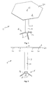
- Figs. 1 to 4 show the collapsible invention Table 1 with a flat formed by a flexible Supporting layer 21 formed table surface 2 and a table surface supporting frame 3.
- the base layer 2 is through in the first view of FIG. 1 hidden folding arms 41st worn from below.
- the table is standing on the ground and will be lowered by the bottom of the Supporting body 31 of the frame 3 mounted support device. 5 stabilized by the laterally projecting Ausstellbeine 51.
- the material of the support layer 21 should be dimensionally stable, tear-resistant, Tensionable, weather, temperature and UV rays resistant be such as Fabric, fabric, rubber, silicone, plastic, Paper, cardboard.
- the materials can also be used in lamella form.
- the basic shape of the table surface can be three, four, five and hexagonal, etc. or round.
- the frame, the folding arms and the legs and the connecting elements are made of solid materials that are suitable for the construction and stabilization of the table are suitable too choose. These materials may, for. For example: metals, plastics, Rubber, silicone, wood, resins.
- FIG. 2 A side view of the assembled table is shown in Fig. 2.
- Fig. 3 the table 1 is shown in a view from below.
- a circumferential tensioning cable 23 is provided at the ends the folding arms is attached.
- Fig. 4 shows the table 1 seen from above.
- FIG. 5 A view of the partially folded support layer 21st and with partially folded Ausstellbeinen 51 is in Fig. 5 is shown. To fold down to the folding arms 41 simply vertically upwards to the mid-perpendicular of the table towards each other, as indicated by the arrows. Likewise, the procedure is with the Ausstellbeinen.
- Fig. 6 shows a stage in which the folding arms and thus the Support layer 21 is still folded further.
- the legs 51 are shown completely folded. In this Position the legs can also serve as a peg, this then in the table supporting the background be plugged in. In this picture was a review chosen so that the spatial relationships become clearer.
- Fig. 7 shows the state then reached.
- the support layer 21 with the folding arms 41 on collapsed towards each other (arrow A) and in another Step into the cavity of the formed as a hollow cylinder Support body 31 inserted (arrow B).
- the support device 5 can work in the same way with the legs 51 inserted ahead in the cavity of the support body 31 become.
- Fig. 8 shows a more detailed view of the bearing body 4 hinged thereto with each in a pivot bearing 42 Folding arms 41.
- the folding arms 41 are for stabilization in a parallel to the pivoting slot guide 45th guided. This is a tilting of the folding arms 41 during prevents the pivoting.
- the final ends of the Slot guides 45 form the supports 43 for the folding arms 41 in which they are in the fully unfolded position support.
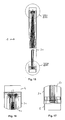
- the bearing body 4 is with its cylindrical lower part (see Fig. 9 in the pulled-out state) in the cavity of the Supporting body 31 up to its stop bead 47 in one inserted in a defined position.
- FIG. 10 and 11 shows in detail the support device 5, the in Fig. 10 to the stop bead 56 with the cylindrical Part (see Fig. 11) in the cavity of the support body 31st is plugged in.
- the Ausstellbeine 51 of the support device. 5 are mounted in leg pivot bearings 53 and are in leg slot guides 57 led. In the fully unfolded state is a support 54 for the Ausstellbeine 51 by the final End of the leg slot guide 57 formed.
- Fig. 12 shows a view of the completely collapsed Table 1 with inserted in the support body 31 bearing body. 4 and inserted support 5.
- the table is open a minimal amount of space reduced.
- FIGS. 13 and 14 show in more detail that the bearing body 4 on the one hand (detail XIV of FIG. 12) and the supporting device 5 to the other (detail XIII of FIG. 12) again each up to whose peripheral stop bead 47 and 56 are inserted.
- Fig. 15 is a collapsed view of the collapsed Table 1 shown.
- the place in the hollow trained Carrying body 31 is used optimally, the table is optimally on smallest dimensions merged.
- Figs. 16 and 17 show an enlarged view of the Areas of the inserted bearing body 4 and the inserted Support device 5 of Fig. 15 (detail XVI and XVII).
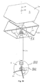
- Fig. 18 is a schematic view obliquely from above to illustrate its entrenched perpendicular bisector in Parts exploded fully unfolded table 1 shown.
- the table surface 2 forming support layer 21 is on attached to her facing tops of the folding arms 41.
- the revolving tensioning cable is at the ends of the folding arms 41st attached and serves for stabilization.
- the support layer 21 is by means of the fastener 22 in its center on Piercing point of the perpendicular bisector M of the table surface 2 with connected to the bearing body 4.
- Fig. 19 shows the detail XIX of Fig. 18.
- the fastener 22 attaches the support layer at the puncture point the median perpendicular M with the bearing body 4 by its inserted into the receptacle 222 of the bearing insert 48 Extension 221. Since the folding arms 41 also with the support layer connected, the folding arms are in their relative Movement restricted. The folding arms 41 are in the slot guides 45 held by their Schenklager 42, by introduced into the introductions 46 of the folding arms 41 bearing ring 44, wherein the bearing ring 44 in a bearing-ring bearing 441 (see also Fig. 22 b) comes to rest.
- folding arms 41 By held in the introducer 46 bearing ring 44 and the by the connection with the attached to the bearing body 4 Supporting layer 21 limited possibility of relative to each other Movement are the folding arms 41 also by the Slotted guide only perpendicular to the perpendicular bisector M movable. Due to the cross-section T-shaped configuration (see Also Fig. 29 c) of the folding arms 41 forms the top of the Bearing insert 48 a support 43 for the fully unfolded Folding arms 41.
- Fig. 20 a and 20 b show the fastening means 22 in one Side view and from above.
- Fig. 21 a and 21 b show the bearing ring 44 in a side view and from above.
- the bearing ring 44 forms the respective Axis of the annularly arranged pivot bearing 42 of the folding arms 41.
- the bearing ring 44 is made of rubber, so can he optimally balance occurring bearing forces.
- Fig. 22 a and 2 b show the bearing insert 48 in a side view and from above.
- the Bearing insert 48 are the Slot guides 45 designed as recesses at the lower end thereby the annularly arranged supports 43 form for the folding arms 41.
- the bearing-ring bearings 441 arranged in a smaller radius as the supports 43 of the folding arms 41.
- Central is the recording 222 for the Extension 221 of the fastener 22 is arranged.
- FIGS. 23 a and 23 b show the lower part of the bearing body 4 on which the stop bead 47 is formed in a side view and from above.
- the shot is 222 for the extension 221 of the fastening means 22 in this Part of the bearing body still continued.
- Figs. 24 and 25 show the detail XXIV and XXV from Fig. 18.
- the support device is in its individual parts shown.
- the leg bearing body 52 is similarly constructed like the bearing body of the folding arms.
- the Ausstellbeine 51 are in leg-slot guides formed in the leg-bearing body 52 57 guided, whereby the Ausstellbeine 51 only vertically are foldable.
- the bearing axles of leg pivot bearings 53 forming bearing ring 55 is in a bearing ring bearing 551 held in the form of a circular groove, the one in one end plate and the other opposite the top Part of the leg-bearing body (see Fig. 26 b) is executed.
- the bearing ring 55 is analogous to the folding arms respectively inserted in an introduction 59 of the Ausstellbeine 51. By the bearing ring held in the grooves and the slot guides thus forms a defined and mechanically safe Guide.
- Figs. 26a and 26b show the upper part of the leg bearing body 52 in a side view and from above.
- the leg slot guide 57 opposite to the leg slot guide of the end plate 58 (see Fig. 28 a and 28 b) executed.
- Outside is circumferential formed the stop bead 56.
- the bearing ring bearing 551 is formed in the form of a circular groove.
- Fig. 27 a and 27 b show the bearing ring 55 in a side view and from above.
- the bearing ring 55 forms each of the Axis of the annularly arranged leg pivot bearings 53 of the Ausstellbeine 51.
- the bearing ring 55 is also like the Bearing ring 44 made of rubber, so it can occur Balance bearing forces optimally.
- Fig. 28 a and 28 b show the end plate 58 in one Side view and from above.
- the leg slot guide 57 is formed in the end plate.
- the webs 571 together with the ends of the leg slot guide incisions in the upper part of the leg bearing body (See Fig. 26 a and 26 b) the support 54 of Ausstellbeine 51. These are arranged so that the Ausstellbeine 51 at an angle of less than 90 ° to the Means perpendicular M of the table surface 2 are fully unfolded.
- the extension legs offer an optimal state of the art Table.
- Figs. 29a, 29b and 29c is a plan view from above, lateral plan view and a side view in the direction a folding arm shown. Due to the T-shaped cross-sectional profile is a good stability of the folding arm secured. The legs are also like the folding arms designed.
- Fig. 29d shows a schematic cross-sectional view through the bearing body 4 with folding arms 41 and by means of Fastener 22 on the bearing body 4 attached support layer 21 in fully unfolded state.
- the bearing ring 44 is located in the Bearing ring bearing 441. Upwards, the bearing ring 44 does not have to be fixed, as he through the folding arms 41 with the support layer 21 are connected, which again with the fastener 22 is connected to the bearing grains 4, fixed is.
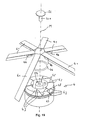
- FIGS. 30 to 53 show a variant of the invention collapsible table 1 shown closer.
- Fig. 30 shows a table with fully folded Ausstellbeinen 51 and almost completely folded Klapparmen 41 with attached support layer 21. On the End cover 70 and the strap 8 will be discussed later.
- Fig. 31 shows an enlarged view of the section XXXI from Fig. 30.
- the bearing body 4 is slidable in the supporting body Stored 31, wherein the bearing body 4 with an outside on Support body 31 slidably guided guide ring 64 by means connected by the guide slot 61 extending screw is.
- a positive guidance for the bearing body 4 formed.
- To take up the support forces is at the end of the Supporting body 31 a screw 631 provided the one End stop 63 forms for the bearing body 4, so that the Forces do not use the forced operation when the table surface is open be derived.
- Fig. 33 shows the table of Fig. 30 with schematically single shown items.
- Fig. 34 shows an enlarged view of the area XXXIV from Fig. 33.
- the guide ring 64 is connected to the bearing body. 4 by a bolt projecting through the guide slot 61 or a screw connected in a provided in the guide ring 64 Thread 642 and one in the lower part of the bearing body 4 provided bolt abutment 641 is mounted.
- Fig. 35 shows an enlarged view of the range XXXV from Fig. 33.
- the guide ring 65 is connected to the support device 5 by a projecting through the guide slot 62 bolt or a screw connected in a in the guide ring 65th provided thread 652 and one in the upper part of the leg bearing body 52 provided bolt abutment 651 stored is.
- Figs. 36 a and 36 b show the end cap 70 in one Side view and from above.
- the end cap 70 is at retracted table surface and support device on the openings the support body 31 is placed and closes this sealing from.
- On the end cover a push button receptacle is formed to which the carrying strap can be attached.
- Figs. 37 a and 37 b show the screw 631 in a Side view and from above.
- FIGS. 38 a and 38 b show the bearing ring 44 in a side view and from above.
- Figs. 39 a and 39 b show the bearing insert 48 in one Side view and from above.
- Figs. 40 a and 40 b show the lower part of the bearing body 4, in which the bolt abutment 641 is formed, in a side view and from above.
- Figs. 41 a and 41 b show the lower part of the guide ring 64, in which the thread 642 is formed in a Side view and from above.
- Figs. 42a and 42b show the upper part of the leg bearing body 52, in which the bolt abutment 651 is formed is, in a side view and from above.
- Figs. 43 a and 43 b show the bearing ring 55 of the support device in a side view and from above.
- Figs. 44 a and 44 b show the end plate 58 in one Side view and from above.
- FIGS. 45 a and 45 b show the screw-in ring 631 of FIG Supporting device in a side view and from above.
- Fig. 46 is a side view and a plan view of obliquely on top of a completely folded table 1 shown after the second variant with forced operation.
- the lightly executed table can be easily carried become.
- the guide slots 61 and 62 are at their ends 612 and 622 running horizontally, whereby the guide ring 64 and 65 must be rotated along the forced operation. Thereby is a locking of the bearing body 4 and the support device 5, so they do not accidentally get back in the hollow body of the support body 31 can be returned.
- Fig. 48 shows in detail the area IID of Fig. 46.
- the two guide rings 64 and 65 are completely withdrawn and touch each other.
- FIG. 49 shows in enlarged detail the area ID from FIG. 47th
- FIG. 50 shows in enlarged detail the region D from FIG. 47.
- FIGS. 51 and 52 the views of FIGS. 46 and 47 are shown in FIG a see-through view shown.
- the support layer 21 is with the folding arms 41 and the bearing body in the support body moved in.
- the support device is completely in housed the hollow body of the support body.
- FIG. 53 shows, according to FIG. 48, the region DII from FIG. 51 in a see-through view.
Landscapes
- Tables And Desks Characterized By Structural Shape (AREA)
- Polyesters Or Polycarbonates (AREA)
- Polyurethanes Or Polyureas (AREA)
- Transition And Organic Metals Composition Catalysts For Addition Polymerization (AREA)
- Holders For Apparel And Elements Relating To Apparel (AREA)
- Accommodation For Nursing Or Treatment Tables (AREA)
Abstract
Description
- Fig. 1
- eine Ansicht von schräg oben auf einen erfindungsgemäßen zusammenlegbaren Tisch,
- Fig. 2
- eine Seitenansicht des erfindungsgemäßen zusammenlegbaren Tisches aus Fig. 1,
- Fig. 3
- eine Ansicht von unten auf den Tisch aus Fig. 1,
- Fig. 4
- eine Ansicht von oben auf den Tisch aus Fig. 1,
- Fig. 5
- eine Draufsicht von schräg oben auf den zusammenlegbaren Tisch, wobei die Tischfläche mit den Klapparmen und die Stützvorrichtung teilweise eingeklappt ist,
- Fig. 6
- eine Draufsicht von schräg oben in Durchsichtdarstellung auf den zusammenlegbaren Tisch, wobei die Tischfläche mit den Klapparmen weiter eingeklappt als in Fig. 5 und die Stützvorrichtung ganz eingeklappt ist,
- Fig. 7
- die Ansicht aus Fig. 6 nachdem die Stützvorrichtung der Lagerkörper mit den Klapparmen und der daran befestigten Tragsicht abgenommen und zum einstecken in den Tragkörper umgedreht wurden,
- Fig. 8
- eine Draufsicht auf eine Detaildarstellung des Ausschnitts VII aus Fig. 6,
- Fig. 9
- eine Draufsicht auf eine Detaildarstellung des Ausschnitts IX aus Fig. 7,
- Fig. 10
- eine Draufsicht auf eine Detaildarstellung des Ausschnitts X aus Fig. 6,
- Fig. 11
- eine Draufsicht auf eine Detaildarstellung des Ausschnitts XI aus Fig. 7,
- Fig. 12
- eine Draufsicht auf einen vollständig zusammengelegten Tisch mit eingesteckter Tischfläche und Stützvorrichtung in dem Tragkörper,
- Fig. 13
- eine Draufsicht auf eine Detaildarstellung des Ausschnitts XIII aus Fig. 12,
- Fig. 14
- eine Draufsicht auf eine Detaildarstellung des Ausschnitts XIV aus Fig. 12,
- Fig. 15
- eine Draufsicht in Durchsichtdarstellung entsprechend Fig. 12,
- Fig. 16
- eine Draufsicht auf eine Detaildarstellung des Ausschnitts XVI aus Fig. 15 in Durchsichtdarstellung entsprechend Fig.. 14,
- Fig. 17
- eine Draufsicht auf eine Detaildarstellung des Ausschnitts XVII aus Fig. 15 in Durchsichtdarstellung entsprechend Fig. 13,
- Fig. 18
- eine schematische Ansicht von schräg oben auf einen teilweise zerlegten und entland seiner Mittelsenkrechten auseinandergezogenen zusammenlegbaren Tisch entsprechend Fig. 1,
- Fig. 19
- eine Draufsicht auf eine Detaildarstellung des Ausschnitts XIX aus Fig. 18,
- Fig. 20a
- eine Seitenansicht des Befestigungsmittels,
- Fig. 20b
- eine Draufsicht von oben auf das Befestigungsmittel,
- Fig. 21a
- eine Seitenansicht des Lager-Rings,
- Fig. 21b
- eine Draufsicht von oben auf den Lager-Ring,
- Fig. 22a
- eine Seitenansicht des Lager-Einsatzes,
- Fig. 22b
- eine Draufsicht von oben auf den Lager-Einsatz,
- Fig. 23a
- eine Seitenansicht des unteren Teils des Lagerkörpers mit Anschlagwulst,
- Fig. 23b
- eine Draufsicht von oben auf den unteren Teil des Lagerkörpers mit Anschlagwulst,
- Fig. 24
- eine Draufsicht auf eine Detaildarstellung des Ausschnitts XXIV aus Fig. 18,
- Fig. 25
- eine Draufsicht auf eine Detaildarstellung des Ausschnitts XXV aus Fig. 18,
- Fig. 26a
- eine Seitenansicht des oberen Teils des Bein-Lagerkörpers mit Anschlagwulst,
- Fig. 26b
- eine Draufsicht von oben auf den oberen Teil des Bein-Lagerkörpers mit Anschlagwulst und Lager-Ring-Lager,
- Fig. 27a
- eine Seitenansicht des Lager-Rings des Bein-Schwenklagers,
- Fig. 27b
- eine Draufsicht von oben auf den Lager-Ring des Bein-Schwenklagers,
- Fig. 28a
- eine Seitenansicht der Abschlussplatte,
- Fig. 28b
- eine Draufsicht von oben auf die Abschlussplatte,
- Fig. 29a
- eine Draufsicht von oben auf einen Klapparm,
- Fig. 29b
- eine seitliche Draufsicht auf einen Klapparm,
- Fig. 29c
- eine Seitenansicht in Verlaufsrichtung eines Klapparms,
- Fig. 29d
- eine schematische Querschnittsdarstellung durch den Lagerkörper mit Klapparmen und Tragschicht im voll ausgeklapptem Zustand,
- Fig. 30
- eine Draufsicht von schräg oben auf eine Variante des zusammenlegbaren erfindungsgemäßen Tisch bei dem der Lagerkörper mit Klapparmen und die Stützvorrichtung entlang einer Zwangsführung in den Tragkörper eingeführt werden können,
- Fig. 31
- eine Draufsicht auf eine Detaildarstellung des Ausschnitts XXXI aus Fig. 30,
- Fig. 32
- eine Draufsicht auf eine Detaildarstellung des Ausschnitts XXXII aus Fig. 30,
- Fig. 33
- eine schematische Ansicht von schräg oben auf einen teilweise zerlegten und entland seiner Mittelsenkrechten auseinandergezogenen zusammenlegbaren Tisch entsprechend Fig. 30,
- Fig. 34
- eine Draufsicht auf eine Detaildarstellung des Ausschnitts XXXIV aus Fig. 33,
- Fig. 35
- eine Draufsicht auf eine Detaildarstellung des Ausschnitts XXXV aus Fig. 33,
- Fig. 36a
- eine Seitenansicht der Abschlusskappe,
- Fig. 36b
- eine Draufsicht von oben auf die Abschlusskappe,
- Fig. 37a
- eine Seitenansicht des Einschraubrings,
- Fig. 37b
- eine Draufsicht von oben auf den Einschraubring,
- Fig. 38a
- eine Seitenansicht des Lager-Rings,
- Fig. 38b
- eine Draufsicht von oben auf den Lager-Ring,
- Fig. 39a
- eine Seitenansicht des Lager-Einsatzes,
- Fig. 39b
- eine Draufsicht von oben auf den Lager-Einsatz,
- Fig. 40a
- eine Seitenansicht des unteren Teils des Lagerkörpers,
- Fig. 40b
- eine Draufsicht von oben auf den unteren Teil des Lagerkörpers,
- Fig. 41a
- eine Seitenansicht des Führungsrings,
- Fig. 41b
- eine Draufsicht von oben auf den Führungsring,
- Fig. 42a
- eine Seitenansicht des oberen Teils des Bein-Lagerkörpers,
- Fig. 42b
- eine Draufsicht von oben auf den oberen Teil des Bein-Lagerkörpers,
- Fig. 43a
- eine Seitenansicht des Lager-Rings,
- Fig. 43b
- eine Draufsicht von oben auf den Lager-Ring,
- Fig. 44a
- eine Seitenansicht der Abschlussplatte,
- Fig. 45b
- eine Draufsicht von oben auf die Abschlussplatte,
- Fig. 45a
- eine Seitenansicht des Einschraubrings der Stützvorrichtung,
- Fig. 45b
- eine Draufsicht von oben auf den Einschraubring der Stützvorrichtung,
- Fig. 46
- eine Seitenansicht des vollkommen zusammengelegten Tisches mit vollständig in dem Tragkörper eingeführten Lagerkörper und Stützvorrichtung sowie mit aufgesetzten Abschlusskappen und daran befestigtem Tragegurt,
- Fig. 47
- eine Draufsicht von schräg oben auf den vollkommen zusammengelegten Tisch aus Fig. 46,
- Fig. 48
- eine Draufsicht auf eine Detaildarstellung des Ausschnitts IID aus Fig. 46,
- Fig. 49
- eine Draufsicht auf eine Detaildarstellung des Ausschnitts ID aus Fig. 46,
- Fig. 50
- eine Draufsicht auf eine Detaildarstellung des Ausschnitts D aus Fig. 46,
- Fig. 51
- eine Seitenansicht in Durchsichtdarstellung auf den zusammengelegten Tisch entsprechend Fig. 46,
- Fig. 52
- eine Draufsicht von schräg oben in Durchsichtdarstellung auf den zusammengelegten Tisch entsprechend Fig. 47, und
- Fig. 53
- eine Draufsicht auf eine Detaildarstellung des Ausschnitts DII in Durchsichtdarstellung aus Fig. 51 entsprechend Fig. 48.
- 1
- zusammenlegbarer Tisch
- 2
- Tischfläche
- 21
- Tragschicht
- 22
- Befestigungselement
- 221
- Fortsatz
- 222
- Aufnahme
- 23
- Spannseil
- 3
- Gestell
- 31
- Tragkörper, Hohlkörper
- 4
- Lagerkörper
- 41
- Klapparme
- 42
- Schwenklager
- 43
- Auflager
- 44
- Lager-Ring
- 441
- Lager-Ring-Lager
- 45
- Schlitzführung
- 46
- Einführung
- 47
- Anschlagwulst
- 48
- Lager-Einsatz
- 5
- Stützvorrichtung
- 51
- Ausstellbein
- 52
- Bein-Lagerkörper
- 53
- Bein-Schwenklager
- 54
- Auflager
- 55
- Lager-Ring
- 551
- Lager-Ring-Lager
- 56
- Anschlagwulst
- 57
- Bein-Schlitzführung
- 571
- Steg
- 58
- Abschlussplatte
- 59
- Einführung
- 61
- Führungsschlitz
- 612
- Ende des Führungsschlitzes
- 62
- Führungsschlitz
- 622
- Ende des Führungsschlitzes
- 63
- Abschlussanschlag
- 631
- Einschraubring
- 64
- Führungsring
- 641
- Bolzen-Widerlager
- 642
- Gewinde
- 65
- Führungsring
- 651
- Bolzen-Widerlager
- 652
- Gewinde
- 70
- Abschlusskappe
- 8
- Tragegurt
- M
- Mittelsenkrechte
Claims (15)
- Zusammenlegbarer Tisch (1), mit einer Tischfläche (2) und einem die Tischfläche tragenden Gestell (3),
dadurch gekennzeichnet, dass die Tischfläche (2) im wesentlichen aus einer flach ausgebildeten flexiblen Tragschicht (21) gebildet ist,
wobei die Tragschicht (2) durch wenigstens drei Klapparme (41) getragen wird, wobei die Klapparme (41) senkrecht zur Tischfläche (2) verschwenkbar an dem Gestell (3) in einem Schwenklager (42) angelenkt sind. - Zusammenlegbarer Tisch nach Anspruch 1,
dadurch gekennzeichnet, dass die Schwenklager (42) in einer zur Tischfläche (2) parallelen Ebene, insbesondere ringförmig um die Mittelsenkrechte (M) der Tischfläche (2) angeordnet sind, wobei die Schwenklager (42) insbesondere an einem Lagerkörper (4) ausgebildet sind, der an einem Tragkörper (31) des Gestells (3) befestigbar ist. - Zusammenlegbarer Tisch nach Anspruch 2,
dadurch gekennzeichnet, dass am Lagerkörper (4) Auflager (43) für die Klapparme (41) vorgesehen sind, die die Klapparme (41) bei vollständig aufgeklappter Verschwenkung, insbesondere 90° gegen die Mittelsenkrechte (M) der Tischfläche (2), unterstützen, wobei die Auflager (43) ringförmig um die Mittelsenkrechte (M) der Tischfläche (2) angeordnet sind, wobei diese in einem größeren Radius als die Schwenklager (42) angeordnet sind. - Zusammenlegbarer Tisch nach einem der vorhergehenden Ansprüche,
dadurch gekennzeichnet, dass die Lagerachsen der Schwenklager (42) durch einen Lager-Ring (44) aus einem elastischen Material, insbesondere Gummi, gebildet sind. - Zusammenlegbarer Tisch nach einem der Ansprüche 1 bis 4,
dadurch gekennzeichnet, dass die Klapparme (41) an ihrer der Tragschicht (21) zugewandten Seite wenigstens Stellenweise mit dieser fest verbunden sind. - Zusammenlegbarer Tisch nach einem der Ansprüche 1 bis 5,
dadurch gekennzeichnet, dass die Tragschicht (21) am Durchstoßpunkt der Mittelsenkrechten (M) der Tischfläche (2) mit dem Lagerkörper (4) verbunden ist. - Zusammenlegbarer Tisch nach einem der vorhergehenden Ansprüche,
dadurch gekennzeichnet, dass die Klapparme (41) am Lagerkörper (4) in einer senkrecht zur Tischfläche (2) angeordneten Schlitzführung (45) geführt sind. - Zusammenlegbarer Tisch nach einem der vorhergehenden Ansprüche,
dadurch gekennzeichnet, dass das Gestell (3) einen langgestreckten Hohlkörper (31) als Tragkörper aufweist. - Zusammenlegbarer Tisch nach Anspruch 8,
dadurch gekennzeichnet, dass die Tragschicht (21) mit den Klapparmen (41) bei vollständig zusammengeklappter Verschwenkung der Klapparme (41) und insbesondere wenigstens teilweise der Lagerkörper (4) in den Hohlkörper (31) des Gestells (3) einsteckbar oder versenkbar ist. - Zusammenlegbarer Tisch nach einem der vorhergehenden Ansprüche,
dadurch gekennzeichnet, dass die Tischfläche (2) von dem Gestell (3) getragen wird,
wobei am unteren, der Tischfläche (2) abgewandten Ende des Gestells (3) eine Stützvorrichtung (5) angeordnet ist, wobei die Stützvorrichtung durch einen Erdnagel oder durch mehrere seitlich und/oder nach unten ragende Ausstellbeine (51) gebildet ist, wobei die Stützvorrichtung (5) insbesondere abnehmbar vom Gestell (3) ausgebildet ist. - Zusammenlegbarer Tisch nach Anspruch 9 oder 10,
dadurch gekennzeichnet, dass die Stützvorrichtung (5) zusammenlegbar ist, wobei insbesondere die Ausstellbeine (51) so zusammenklappbar sind, dass die Stützvorrichtung (5) in den Hohlkörper (31) des Gestells (3) einsteckbar oder versenkbar ist. - Zusammenlegbarer Tisch nach einem der vorhergehenden Ansprüche,
dadurch gekennzeichnet, dass die Ausstellbeine (51) senkrecht zur Tischfläche (2) verschwenkbar an dem Gestell (3) in einem Bein-Schwenklager (53) angelenkt sind, wobei insbesondere die Bein-Schwenklager ringförmig um die Mittelsenkrechte (M) der Tischfläche (2) in einer zur Tischfläche (2) parallelen Ebene angeordnet sind,
wobei insbesondere die Bein-Schwenklager (53) an einem Bein-Lagerkörper (52) ausgebildet sind, der an einem Tragkörper (31) des Gestells (3) befestigbar ist, dass an dem Bein-Lagerkörper (52) Auflager (54) für die Ausstellbeine (51) vorgesehen sind, die die Ausstellbeine (51) bei vollständig aufgeklappter Verschwenkung, insbesondere kleiner 90° gegen die Mittelsenkrechte (M) der Tischfläche (2), unterstützen. - Zusammenlegbarer Tisch nach Anspruch 12,
dadurch gekennzeichnet, dass die Ausstellbeine (51) am Bein-Lagerkörper (52) in einer senkrecht zur Tischfläche (2) angeordneten Bein-Schlitzführung (57) geführt sind. - Zusammenlegbarer Tisch nach einem der vorhergehenden Ansprüche,
dadurch gekennzeichnet, dass in der Wand des Hohlkörpers (31) eine Zwangsführung insbesondere in Form eines Führungsschlitzes (61 oder 62) ausgebildet ist, entlang welcher der Lagerkörper (4) und/oder die Bein-Lagerkörper (52) im Hohlkörper (31) verschieblich geführt werden können, wobei insbesondere außen am Hohlkörper (31) ein Führungsring (64 oder 65) verschieblich gelagert ist, der mit dem Lagerkörper (4) oder der Bein-Lagerkörper (52) durch den Führungsschlitz (61 oder 62) durch einen Bolzen verbunden ist. - Zusammenlegbarer Tisch nach einem der vorhergehenden Ansprüche,
dadurch gekennzeichnet, dass der Tragkörper (31) in zwei Abschnitte unterteilt ist,
wobei diese mit unterschiedlichem Durchmesser ausgestaltet sind und die Abschnitte ineinander gesteckt sind.
Applications Claiming Priority (2)
| Application Number | Priority Date | Filing Date | Title |
|---|---|---|---|
| DE20319639U DE20319639U1 (de) | 2003-12-17 | 2003-12-17 | Zusammenlegbarer Tisch |
| DE20319639U | 2003-12-17 |
Publications (2)
| Publication Number | Publication Date |
|---|---|
| EP1543743A1 true EP1543743A1 (de) | 2005-06-22 |
| EP1543743B1 EP1543743B1 (de) | 2007-02-28 |
Family
ID=31984862
Family Applications (1)
| Application Number | Title | Priority Date | Filing Date |
|---|---|---|---|
| EP04029970A Expired - Lifetime EP1543743B1 (de) | 2003-12-17 | 2004-12-17 | Zusammenlegbarer Tisch |
Country Status (3)
| Country | Link |
|---|---|
| EP (1) | EP1543743B1 (de) |
| AT (1) | ATE354987T1 (de) |
| DE (2) | DE20319639U1 (de) |
Cited By (1)
| Publication number | Priority date | Publication date | Assignee | Title |
|---|---|---|---|---|
| CN114365928A (zh) * | 2022-01-13 | 2022-04-19 | 迅镭(广州)智能科技股份有限公司 | 一种供销售人员使用的便携式折叠视频展台 |
Families Citing this family (2)
| Publication number | Priority date | Publication date | Assignee | Title |
|---|---|---|---|---|
| DE102017220863A1 (de) * | 2017-11-22 | 2019-05-23 | Brose Fahrzeugteile Gmbh & Co. Kg, Coburg | Falttisch für ein Kraftfahrzeug |
| DE102024202617A1 (de) * | 2024-03-20 | 2025-09-25 | Volkswagen Aktiengesellschaft | Tisch für ein Fahrzeug mit einem textilen Material, Fahrzeugsitz und Fahrzeug mit einem solchen |
Citations (3)
| Publication number | Priority date | Publication date | Assignee | Title |
|---|---|---|---|---|
| US5421273A (en) * | 1994-03-14 | 1995-06-06 | Lin; Yuan-Hsiung | Collapsible table |
| US6505565B1 (en) * | 2000-03-28 | 2003-01-14 | Northpole Us Llc | Collapsible table with elastic retaining elements |
| US6536732B1 (en) * | 2000-07-17 | 2003-03-25 | Tony Wei-Sin Chang | Swivel mechanism for foldable furniture |
-
2003
- 2003-12-17 DE DE20319639U patent/DE20319639U1/de not_active Expired - Lifetime
-
2004
- 2004-12-17 AT AT04029970T patent/ATE354987T1/de active
- 2004-12-17 DE DE502004003026T patent/DE502004003026D1/de not_active Expired - Lifetime
- 2004-12-17 EP EP04029970A patent/EP1543743B1/de not_active Expired - Lifetime
Patent Citations (3)
| Publication number | Priority date | Publication date | Assignee | Title |
|---|---|---|---|---|
| US5421273A (en) * | 1994-03-14 | 1995-06-06 | Lin; Yuan-Hsiung | Collapsible table |
| US6505565B1 (en) * | 2000-03-28 | 2003-01-14 | Northpole Us Llc | Collapsible table with elastic retaining elements |
| US6536732B1 (en) * | 2000-07-17 | 2003-03-25 | Tony Wei-Sin Chang | Swivel mechanism for foldable furniture |
Cited By (1)
| Publication number | Priority date | Publication date | Assignee | Title |
|---|---|---|---|---|
| CN114365928A (zh) * | 2022-01-13 | 2022-04-19 | 迅镭(广州)智能科技股份有限公司 | 一种供销售人员使用的便携式折叠视频展台 |
Also Published As
| Publication number | Publication date |
|---|---|
| DE502004003026D1 (de) | 2007-04-12 |
| EP1543743B1 (de) | 2007-02-28 |
| ATE354987T1 (de) | 2006-03-15 |
| DE20319639U1 (de) | 2004-03-04 |
Similar Documents
| Publication | Publication Date | Title |
|---|---|---|
| DE8914512U1 (de) | Sonnenschirm | |
| DE202010016203U1 (de) | Klappbarer Tisch | |
| EP1543743B1 (de) | Zusammenlegbarer Tisch | |
| DE10359453A1 (de) | Zusammenlegbarer Tisch | |
| DE202010014601U1 (de) | Variierbare gekoppelte Sitzgruppe | |
| EP1195112A1 (de) | Klapptisch | |
| DE202012008101U1 (de) | Bühnenpodestelement | |
| DE3119606A1 (de) | Ausziehtisch | |
| DE102004043192B4 (de) | Tisch | |
| DE202011109084U1 (de) | Klapptisch | |
| DE3815196C2 (de) | Schwenktafel | |
| DE102004002688B4 (de) | Transportabler Anbautisch | |
| EP1523905B1 (de) | Tisch mit klappbaren Beinen | |
| EP2095739A1 (de) | Klapptisch | |
| DE202011004336U1 (de) | Klapptisch | |
| DE60301170T2 (de) | Möbelstück | |
| EP1038465A2 (de) | Schirmständer | |
| DE20014540U1 (de) | Beschlag zur Abstützung einer Eckschranktür | |
| CH700935B1 (de) | Stapelfähiger Tisch. | |
| DE19957957A1 (de) | Klappbarer Arbeits-, Studien- und Seminartisch oder klappbarer kombinierter Pult/Tisch | |
| DE102004054130B3 (de) | Tisch mit vergrößerbarer Tischplatte | |
| DE20003897U1 (de) | Ausziehtisch | |
| DE3931167A1 (de) | Tisch-beistelltisch-kombination | |
| DE8315514U1 (de) | Zusammenlegbarer Notenständer | |
| CH687057A5 (de) | Klapptisch |
Legal Events
| Date | Code | Title | Description |
|---|---|---|---|
| PUAI | Public reference made under article 153(3) epc to a published international application that has entered the european phase |
Free format text: ORIGINAL CODE: 0009012 |
|
| AK | Designated contracting states |
Kind code of ref document: A1 Designated state(s): AT BE BG CH CY CZ DE DK EE ES FI FR GB GR HU IE IS IT LI LT LU MC NL PL PT RO SE SI SK TR |
|
| AX | Request for extension of the european patent |
Extension state: AL BA HR LV MK YU |
|
| 17P | Request for examination filed |
Effective date: 20051114 |
|
| AKX | Designation fees paid |
Designated state(s): AT BE BG CH CY CZ DE DK EE ES FI FR GB GR HU IE IS IT LI LT LU MC NL PL PT RO SE SI SK TR |
|
| GRAP | Despatch of communication of intention to grant a patent |
Free format text: ORIGINAL CODE: EPIDOSNIGR1 |
|
| GRAS | Grant fee paid |
Free format text: ORIGINAL CODE: EPIDOSNIGR3 |
|
| GRAA | (expected) grant |
Free format text: ORIGINAL CODE: 0009210 |
|
| AK | Designated contracting states |
Kind code of ref document: B1 Designated state(s): AT BE BG CH CY CZ DE DK EE ES FI FR GB GR HU IE IS IT LI LT LU MC NL PL PT RO SE SI SK TR |
|
| PG25 | Lapsed in a contracting state [announced via postgrant information from national office to epo] |
Ref country code: NL Free format text: LAPSE BECAUSE OF FAILURE TO SUBMIT A TRANSLATION OF THE DESCRIPTION OR TO PAY THE FEE WITHIN THE PRESCRIBED TIME-LIMIT Effective date: 20070228 Ref country code: SI Free format text: LAPSE BECAUSE OF FAILURE TO SUBMIT A TRANSLATION OF THE DESCRIPTION OR TO PAY THE FEE WITHIN THE PRESCRIBED TIME-LIMIT Effective date: 20070228 Ref country code: IE Free format text: LAPSE BECAUSE OF FAILURE TO SUBMIT A TRANSLATION OF THE DESCRIPTION OR TO PAY THE FEE WITHIN THE PRESCRIBED TIME-LIMIT Effective date: 20070228 Ref country code: FI Free format text: LAPSE BECAUSE OF FAILURE TO SUBMIT A TRANSLATION OF THE DESCRIPTION OR TO PAY THE FEE WITHIN THE PRESCRIBED TIME-LIMIT Effective date: 20070228 Ref country code: DK Free format text: LAPSE BECAUSE OF FAILURE TO SUBMIT A TRANSLATION OF THE DESCRIPTION OR TO PAY THE FEE WITHIN THE PRESCRIBED TIME-LIMIT Effective date: 20070228 Ref country code: PL Free format text: LAPSE BECAUSE OF FAILURE TO SUBMIT A TRANSLATION OF THE DESCRIPTION OR TO PAY THE FEE WITHIN THE PRESCRIBED TIME-LIMIT Effective date: 20070228 |
|
| REG | Reference to a national code |
Ref country code: GB Ref legal event code: FG4D Free format text: NOT ENGLISH |
|
| REG | Reference to a national code |
Ref country code: CH Ref legal event code: EP |
|
| REF | Corresponds to: |
Ref document number: 502004003026 Country of ref document: DE Date of ref document: 20070412 Kind code of ref document: P |
|
| REG | Reference to a national code |
Ref country code: IE Ref legal event code: FG4D Free format text: LANGUAGE OF EP DOCUMENT: GERMAN |
|
| REG | Reference to a national code |
Ref country code: CH Ref legal event code: NV Representative=s name: MEYER & KOLLEGEN |
|
| PG25 | Lapsed in a contracting state [announced via postgrant information from national office to epo] |
Ref country code: BG Free format text: LAPSE BECAUSE OF FAILURE TO SUBMIT A TRANSLATION OF THE DESCRIPTION OR TO PAY THE FEE WITHIN THE PRESCRIBED TIME-LIMIT Effective date: 20070528 |
|
| PG25 | Lapsed in a contracting state [announced via postgrant information from national office to epo] |
Ref country code: SE Free format text: LAPSE BECAUSE OF FAILURE TO SUBMIT A TRANSLATION OF THE DESCRIPTION OR TO PAY THE FEE WITHIN THE PRESCRIBED TIME-LIMIT Effective date: 20070531 |
|
| PG25 | Lapsed in a contracting state [announced via postgrant information from national office to epo] |
Ref country code: ES Free format text: LAPSE BECAUSE OF FAILURE TO SUBMIT A TRANSLATION OF THE DESCRIPTION OR TO PAY THE FEE WITHIN THE PRESCRIBED TIME-LIMIT Effective date: 20070608 |
|
| PG25 | Lapsed in a contracting state [announced via postgrant information from national office to epo] |
Ref country code: IS Free format text: LAPSE BECAUSE OF FAILURE TO SUBMIT A TRANSLATION OF THE DESCRIPTION OR TO PAY THE FEE WITHIN THE PRESCRIBED TIME-LIMIT Effective date: 20070628 |
|
| PG25 | Lapsed in a contracting state [announced via postgrant information from national office to epo] |
Ref country code: PT Free format text: LAPSE BECAUSE OF FAILURE TO SUBMIT A TRANSLATION OF THE DESCRIPTION OR TO PAY THE FEE WITHIN THE PRESCRIBED TIME-LIMIT Effective date: 20070730 |
|
| NLV1 | Nl: lapsed or annulled due to failure to fulfill the requirements of art. 29p and 29m of the patents act | ||
| GBV | Gb: ep patent (uk) treated as always having been void in accordance with gb section 77(7)/1977 [no translation filed] |
Effective date: 20070228 |
|
| REG | Reference to a national code |
Ref country code: IE Ref legal event code: FD4D |
|
| EN | Fr: translation not filed | ||
| PG25 | Lapsed in a contracting state [announced via postgrant information from national office to epo] |
Ref country code: SK Free format text: LAPSE BECAUSE OF FAILURE TO SUBMIT A TRANSLATION OF THE DESCRIPTION OR TO PAY THE FEE WITHIN THE PRESCRIBED TIME-LIMIT Effective date: 20070228 Ref country code: GB Free format text: LAPSE BECAUSE OF FAILURE TO SUBMIT A TRANSLATION OF THE DESCRIPTION OR TO PAY THE FEE WITHIN THE PRESCRIBED TIME-LIMIT Effective date: 20070228 |
|
| PG25 | Lapsed in a contracting state [announced via postgrant information from national office to epo] |
Ref country code: CZ Free format text: LAPSE BECAUSE OF FAILURE TO SUBMIT A TRANSLATION OF THE DESCRIPTION OR TO PAY THE FEE WITHIN THE PRESCRIBED TIME-LIMIT Effective date: 20070228 Ref country code: RO Free format text: LAPSE BECAUSE OF FAILURE TO SUBMIT A TRANSLATION OF THE DESCRIPTION OR TO PAY THE FEE WITHIN THE PRESCRIBED TIME-LIMIT Effective date: 20070228 |
|
| PLBE | No opposition filed within time limit |
Free format text: ORIGINAL CODE: 0009261 |
|
| STAA | Information on the status of an ep patent application or granted ep patent |
Free format text: STATUS: NO OPPOSITION FILED WITHIN TIME LIMIT |
|
| 26N | No opposition filed |
Effective date: 20071129 |
|
| PG25 | Lapsed in a contracting state [announced via postgrant information from national office to epo] |
Ref country code: LT Free format text: LAPSE BECAUSE OF FAILURE TO SUBMIT A TRANSLATION OF THE DESCRIPTION OR TO PAY THE FEE WITHIN THE PRESCRIBED TIME-LIMIT Effective date: 20070228 |
|
| PG25 | Lapsed in a contracting state [announced via postgrant information from national office to epo] |
Ref country code: GR Free format text: LAPSE BECAUSE OF FAILURE TO SUBMIT A TRANSLATION OF THE DESCRIPTION OR TO PAY THE FEE WITHIN THE PRESCRIBED TIME-LIMIT Effective date: 20070529 Ref country code: IT Free format text: LAPSE BECAUSE OF FAILURE TO SUBMIT A TRANSLATION OF THE DESCRIPTION OR TO PAY THE FEE WITHIN THE PRESCRIBED TIME-LIMIT Effective date: 20070228 Ref country code: FR Free format text: LAPSE BECAUSE OF FAILURE TO SUBMIT A TRANSLATION OF THE DESCRIPTION OR TO PAY THE FEE WITHIN THE PRESCRIBED TIME-LIMIT Effective date: 20071019 |
|
| BERE | Be: lapsed |
Owner name: TECH GISELA Effective date: 20071231 |
|
| PG25 | Lapsed in a contracting state [announced via postgrant information from national office to epo] |
Ref country code: MC Free format text: LAPSE BECAUSE OF NON-PAYMENT OF DUE FEES Effective date: 20071231 |
|
| PG25 | Lapsed in a contracting state [announced via postgrant information from national office to epo] |
Ref country code: BE Free format text: LAPSE BECAUSE OF NON-PAYMENT OF DUE FEES Effective date: 20071231 |
|
| PG25 | Lapsed in a contracting state [announced via postgrant information from national office to epo] |
Ref country code: FR Free format text: LAPSE BECAUSE OF FAILURE TO SUBMIT A TRANSLATION OF THE DESCRIPTION OR TO PAY THE FEE WITHIN THE PRESCRIBED TIME-LIMIT Effective date: 20070228 |
|
| PG25 | Lapsed in a contracting state [announced via postgrant information from national office to epo] |
Ref country code: EE Free format text: LAPSE BECAUSE OF FAILURE TO SUBMIT A TRANSLATION OF THE DESCRIPTION OR TO PAY THE FEE WITHIN THE PRESCRIBED TIME-LIMIT Effective date: 20070228 |
|
| PG25 | Lapsed in a contracting state [announced via postgrant information from national office to epo] |
Ref country code: CY Free format text: LAPSE BECAUSE OF FAILURE TO SUBMIT A TRANSLATION OF THE DESCRIPTION OR TO PAY THE FEE WITHIN THE PRESCRIBED TIME-LIMIT Effective date: 20070228 |
|
| PG25 | Lapsed in a contracting state [announced via postgrant information from national office to epo] |
Ref country code: LU Free format text: LAPSE BECAUSE OF NON-PAYMENT OF DUE FEES Effective date: 20071217 |
|
| PG25 | Lapsed in a contracting state [announced via postgrant information from national office to epo] |
Ref country code: HU Free format text: LAPSE BECAUSE OF FAILURE TO SUBMIT A TRANSLATION OF THE DESCRIPTION OR TO PAY THE FEE WITHIN THE PRESCRIBED TIME-LIMIT Effective date: 20070901 Ref country code: TR Free format text: LAPSE BECAUSE OF FAILURE TO SUBMIT A TRANSLATION OF THE DESCRIPTION OR TO PAY THE FEE WITHIN THE PRESCRIBED TIME-LIMIT Effective date: 20070228 |
|
| REG | Reference to a national code |
Ref country code: CH Ref legal event code: PCAR Free format text: MEYER & KOLLEGEN;RINGSTRASSE 35C;7000 CHUR (CH) |
|
| PGFP | Annual fee paid to national office [announced via postgrant information from national office to epo] |
Ref country code: AT Payment date: 20130228 Year of fee payment: 9 |
|
| REG | Reference to a national code |
Ref country code: AT Ref legal event code: MM01 Ref document number: 354987 Country of ref document: AT Kind code of ref document: T Effective date: 20131217 |
|
| PG25 | Lapsed in a contracting state [announced via postgrant information from national office to epo] |
Ref country code: AT Free format text: LAPSE BECAUSE OF NON-PAYMENT OF DUE FEES Effective date: 20131217 |
|
| PGFP | Annual fee paid to national office [announced via postgrant information from national office to epo] |
Ref country code: CH Payment date: 20150120 Year of fee payment: 11 Ref country code: DE Payment date: 20150113 Year of fee payment: 11 |
|
| REG | Reference to a national code |
Ref country code: DE Ref legal event code: R119 Ref document number: 502004003026 Country of ref document: DE |
|
| REG | Reference to a national code |
Ref country code: CH Ref legal event code: PL |
|
| PG25 | Lapsed in a contracting state [announced via postgrant information from national office to epo] |
Ref country code: LI Free format text: LAPSE BECAUSE OF NON-PAYMENT OF DUE FEES Effective date: 20151231 Ref country code: CH Free format text: LAPSE BECAUSE OF NON-PAYMENT OF DUE FEES Effective date: 20151231 Ref country code: DE Free format text: LAPSE BECAUSE OF NON-PAYMENT OF DUE FEES Effective date: 20160701 |