EP1543793A2 - Instrument pour répartir un matériau de restauration sur la surface d'une dent - Google Patents
Instrument pour répartir un matériau de restauration sur la surface d'une dent Download PDFInfo
- Publication number
- EP1543793A2 EP1543793A2 EP04257800A EP04257800A EP1543793A2 EP 1543793 A2 EP1543793 A2 EP 1543793A2 EP 04257800 A EP04257800 A EP 04257800A EP 04257800 A EP04257800 A EP 04257800A EP 1543793 A2 EP1543793 A2 EP 1543793A2
- Authority
- EP
- European Patent Office
- Prior art keywords
- working end
- dental instrument
- roller
- roller tip
- bushing
- Prior art date
- Legal status (The legal status is an assumption and is not a legal conclusion. Google has not performed a legal analysis and makes no representation as to the accuracy of the status listed.)
- Granted
Links
- 239000000463 material Substances 0.000 title claims abstract description 75
- 239000004033 plastic Substances 0.000 claims description 28
- 229920003023 plastic Polymers 0.000 claims description 28
- 239000000654 additive Substances 0.000 claims description 25
- 230000000996 additive effect Effects 0.000 claims description 25
- 238000005096 rolling process Methods 0.000 claims description 15
- 210000000214 mouth Anatomy 0.000 claims description 8
- -1 polytetrafluoroethylene Polymers 0.000 claims description 8
- 229920001343 polytetrafluoroethylene Polymers 0.000 claims description 6
- 239000004810 polytetrafluoroethylene Substances 0.000 claims description 6
- 229920000049 Carbon (fiber) Polymers 0.000 claims description 4
- 239000004917 carbon fiber Substances 0.000 claims description 4
- 239000004696 Poly ether ether ketone Substances 0.000 claims description 2
- 239000004695 Polyether sulfone Substances 0.000 claims description 2
- 239000004697 Polyetherimide Substances 0.000 claims description 2
- 229920000491 Polyphenylsulfone Polymers 0.000 claims description 2
- 239000003365 glass fiber Substances 0.000 claims description 2
- 229920001707 polybutylene terephthalate Polymers 0.000 claims description 2
- 229920006393 polyether sulfone Polymers 0.000 claims description 2
- 229920002530 polyetherether ketone Polymers 0.000 claims description 2
- 229920001601 polyetherimide Polymers 0.000 claims description 2
- 229920006375 polyphtalamide Polymers 0.000 claims description 2
- 229920001296 polysiloxane Polymers 0.000 claims description 2
- 239000004814 polyurethane Substances 0.000 claims description 2
- 229920002725 thermoplastic elastomer Polymers 0.000 claims description 2
- 229920002803 thermoplastic polyurethane Polymers 0.000 claims 1
- 239000002131 composite material Substances 0.000 description 10
- 238000010276 construction Methods 0.000 description 5
- 238000007493 shaping process Methods 0.000 description 5
- 230000008901 benefit Effects 0.000 description 3
- 235000019589 hardness Nutrition 0.000 description 3
- 239000011159 matrix material Substances 0.000 description 3
- 238000000034 method Methods 0.000 description 3
- 239000004812 Fluorinated ethylene propylene Substances 0.000 description 2
- YCKRFDGAMUMZLT-UHFFFAOYSA-N Fluorine atom Chemical compound [F] YCKRFDGAMUMZLT-UHFFFAOYSA-N 0.000 description 2
- 229920001774 Perfluoroether Polymers 0.000 description 2
- 239000011248 coating agent Substances 0.000 description 2
- 238000000576 coating method Methods 0.000 description 2
- HQQADJVZYDDRJT-UHFFFAOYSA-N ethene;prop-1-ene Chemical group C=C.CC=C HQQADJVZYDDRJT-UHFFFAOYSA-N 0.000 description 2
- 239000011737 fluorine Substances 0.000 description 2
- 229910052731 fluorine Inorganic materials 0.000 description 2
- 238000009499 grossing Methods 0.000 description 2
- 230000010354 integration Effects 0.000 description 2
- CWQXQMHSOZUFJS-UHFFFAOYSA-N molybdenum disulfide Chemical compound S=[Mo]=S CWQXQMHSOZUFJS-UHFFFAOYSA-N 0.000 description 2
- 229910052982 molybdenum disulfide Inorganic materials 0.000 description 2
- 229920009441 perflouroethylene propylene Polymers 0.000 description 2
- 230000008569 process Effects 0.000 description 2
- 230000009467 reduction Effects 0.000 description 2
- 239000012858 resilient material Substances 0.000 description 2
- 230000007480 spreading Effects 0.000 description 2
- BQHQZFUAEAVJRE-UHFFFAOYSA-N 2-fluorobuta-1,3-diene Chemical compound FC(=C)C=C BQHQZFUAEAVJRE-UHFFFAOYSA-N 0.000 description 1
- 229920002449 FKM Polymers 0.000 description 1
- 229910000831 Steel Inorganic materials 0.000 description 1
- 239000004809 Teflon Substances 0.000 description 1
- 229920006362 Teflon® Polymers 0.000 description 1
- 229910010380 TiNi Inorganic materials 0.000 description 1
- 125000000218 acetic acid group Chemical group C(C)(=O)* 0.000 description 1
- 239000011230 binding agent Substances 0.000 description 1
- 239000002801 charged material Substances 0.000 description 1
- 239000003086 colorant Substances 0.000 description 1
- 230000006835 compression Effects 0.000 description 1
- 238000007906 compression Methods 0.000 description 1
- 208000002925 dental caries Diseases 0.000 description 1
- 239000005548 dental material Substances 0.000 description 1
- 229920001971 elastomer Polymers 0.000 description 1
- 239000000806 elastomer Substances 0.000 description 1
- 229920001973 fluoroelastomer Polymers 0.000 description 1
- 230000002452 interceptive effect Effects 0.000 description 1
- 230000014759 maintenance of location Effects 0.000 description 1
- 238000005259 measurement Methods 0.000 description 1
- 239000012229 microporous material Substances 0.000 description 1
- 238000012986 modification Methods 0.000 description 1
- 230000004048 modification Effects 0.000 description 1
- 229920006131 poly(hexamethylene isophthalamide-co-terephthalamide) Polymers 0.000 description 1
- 229920002635 polyurethane Polymers 0.000 description 1
- 229920005989 resin Polymers 0.000 description 1
- 239000011347 resin Substances 0.000 description 1
- 239000011343 solid material Substances 0.000 description 1
- 239000010959 steel Substances 0.000 description 1
- 239000000126 substance Substances 0.000 description 1
- 229920006342 thermoplastic vulcanizate Polymers 0.000 description 1
Images


Classifications
-
- A—HUMAN NECESSITIES
- A61—MEDICAL OR VETERINARY SCIENCE; HYGIENE
- A61C—DENTISTRY; APPARATUS OR METHODS FOR ORAL OR DENTAL HYGIENE
- A61C3/00—Dental tools or instruments
- A61C3/08—Tooth pluggers or hammers
Definitions
- This invention relates to a dental instrument for homogeneously applying and shaping tooth restorative material, and specifically, a dental instrument with interchangeable roller tips for distributing the restorative material.
- Composite materials i.e., tooth restorative materials containing binders in the form of hardenable, generally organic substances, have become the standard filling materials in dentistry.
- a disadvantage of these composite materials is their tendency to adhere more or less to the instrument that is used to apply or shape them.
- the composite material has a tendency to be drawn off from the edges of the cavity, to be distributed inhomogeneously on the tooth surface, and to form air bubbles during the distribution.
- the instruments used for distributing the restorative material typically comprise a steel instrument with an uncoated working tip portion or a tip portion coated with TiNi, for example, or a plastic material with or without a coated or treated working tip portion.
- the present invention in a preferred embodiment provides a dental instrument with interchangeable roller tips for distributing restorative materials on a tooth surface, which roller tips distribute the restorative material quickly, precisely and homogeneously with little adherence of the restorative material to the roller tip due, in part, to the short contact time between the roller tip and the composite material.
- a dental instrument having an elongate body with a handle portion and a working end extending therefrom.
- a roller tip is rotatably mounted on the working end so as to rotate about a center axis of the end of the instrument, and is sized to distribute the restorative material on a tooth surface, including a cavity surface.
- the roller tip is removable from the working end, such that differently shaped tips may be placed on the working end during the restoration of the tooth, as necessary, to ensure complete and even coverage to an uneven surface.
- a bushing or rolling element bearing is rotatably mounted on the working end between the working end and the roller tip, such that the roller tip is rotatable on the working end by means of the rotatable bushing or bearing.
- the dental instrument includes two working ends extending in opposing directions from the handle portion to provide different angles for the working ends or to provide differently shaped roller tips on the working ends.
- FIG. 1 is a perspective view of a dental instrument of the present invention
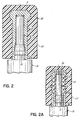
- FIG. 2 is a cross-sectional view of a first working end of the instrument of FIG. 1, as taken along line 2-2;
- FIG. 2A is a cross-sectional view of an alternative embodiment of the first working end of the instrument of FIG. 1, also taken along line 2-2;
- FIG. 3 depicts a side elevational view of an alternative embodiment of a dental instrument of the present invention with the working end in partial cross-section;
- FIGS. 4A-4C depict various embodiments for the roller tips of the instrument of the present invention.
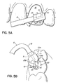
- FIGS. 5A-5B depict uses of an instrument of the present invention in applying and shaping restorative materials on tooth surfaces.
- FIGS. 1-5B An exemplary dental instrument 10 is depicted in perspective view in FIG. 1.
- Instrument 10 at least in the depicted preferred form, is designed for distributing tooth restorative materials on a tooth surface within the oral cavity of a patient, i.e. within the patient's mouth, without the adherence problems of the prior art.
- Instrument 10 is also designed for distributing tooth restorative materials on an artificial tooth surface to form a prosthetic tooth.
- Instrument 10 has an elongate body 12 with a first working end 14 and a second working end 16 that extend from opposite ends 18a, 18b of a handle portion 18. As shown in FIG.
- the first working end 14 extends from end 18a of the handle portion 18 such that its center axis is substantially coaxial with the center axis of the handle portion 18.
- This construction may be referred to as an axial working end.
- the second working end 16 extends from end 18b of the handle portion 18 in a direction such that its center axis is perpendicular (90°) to the center axis of the handle portion 18.
- This construction may be referred to as a right angle working end.
- differently angled working ends allow the dentist to choose the appropriate angle for most effectively distributing the restorative material on the tooth surface, particularly where the tooth surface is located in the oral cavity.
- both working ends 14, 16 may be coaxial with the center axis of the handle portion 18 or both ends 14, 16 may be angled relative to the center axis of the handle portion 18.
- the particular angles for the first and second working ends 14, 16 depicted in FIG. 1 are not intended to limit the configuration of the instrument 10 of the present invention.
- first and second working ends 14, 16 are depicted with a roller tip 20, 20a, respectively, sized to distribute restorative material on a tooth surface, wherein tips 20, 20a are removable from the first and second working ends 14, 16 and interchangeable with each other or with other roller tips 20.
- An exemplary embodiment of the roller tip 20 is more clearly depicted in cross-sectional view in FIG. 2, as taken along line 2-2 of FIG. 1.
- the first working end 14 is shown having a reduced diameter as compared to the diameter of the remaining portion of the elongate body 12, including handle portion 18, but the invention is not so limited.
- mounted on the first working end 14 is a bushing 30, which is rotatable on the first working end 14 about the center axis of the first working end 14.
- the roller tip 20 is mounted on, and rotatable with, the bushing 30 so as to be rotatable about the first working end 14 by means of the rotation of the rotatable bushing 30, which rotates relative to working end 14. Because the center of the roller tip 20 is coaxial with the center of the working end 14 of the instrument 10 in this exemplary embodiment, torque is avoided during rotation of the roller tip 20 to distribute the restorative material. While the roller tip 20 is depicted as a closed cylinder at distal end 15, it may be appreciated that the roller tip 20 may be an open cylinder at distal end 15 thereby exposing the bushing 30. However, the exemplary embodiment shown in FIG.
- roller tip 20 is advantageous in that it prevents restorative material from entering into the bushing area and interfering with operation of the rotatable tip 20 and bushing 30.
- Roller tip 20 is further shown having a substantially uniformly cylindrical surface 22 for distributing restorative material on a tooth surface. It may be appreciated, however, as will be discussed in more detail below, that roller tip 20 may be shaped to have a non-uniform outer surface 22.
- bushing 30 includes a clip portion 32 for engaging a ridge portion 13 of first working end 14.
- Clip portion 32 prevents restorative material from getting between the bushing 30 and the first working end 14.
- Clip portion 32 further assists in the retention and easy removal of the roller tip 20 such that the roller tip 20 is interchangeable with other roller tips.
- a bulbous shape for top portion 31 of bushing 30 is also advantageous in that it also assists in the interchangeability of roller tip 20 without the risk of axial disassembling.
- a similar construction for bushing 30 may be used at second working end 16.
- the elongate body 12, including first and second working ends 14, 16 and/or bushing 30, comprise a plastic material containing a friction-reducing additive to facilitate rotation of the bushings 30 around the first and second working ends 14, 16.
- Friction is the force that retards, that is partially brakes, the movement of two surfaces against each other
- the kinetic coefficient of friction, ⁇ is a measurement of the extent of friction present during rotation. The kinetic coefficient of friction is measured by dividing the frictional resistance force, f, by the normal force, N, that presses the two surfaces together when they move relative to each other.
- the amount of friction-reducing material in one or both of the elongate body 12 and bushings 30 is sufficient to provide a kinetic coefficient of friction of less than 0.2 between the first working end 14 and the bushing 30 on which the roller tip 20 is mounted, and between the second working end 16 and the bushing 30 on which roller tip 20a is mounted.
- the elongate body 12 comprises a plastic material containing 2-30 wt.% of a friction-reducing additive.
- the bushings 30 comprise a plastic material containing 2-30 wt.% of a friction-reducing additive.
- each of the elongate body 12 and the bushings 30 comprise a plastic material containing 2-30 wt.% of a friction-reducing additive.
- the friction-reducing additive is advantageously polytetrafluoroethylene present in an amount of 2 20 wt.%, and more advantageously, the polytetrafluoroethylene is present in an amount of 5-15 wt.%.
- fluorinated ethylene propylene, perfluoroalkoxy copolymers, carbon fibers and molybdenum disulfide may be also be effective to provide a low coefficient of friction.
- fluorinated ethylene propylene and perfluoroalkoxy copolymers are advantageously present in an amount of 2-20 wt.% of the plastic material, while carbon fibers are advantageously present in an amount of 5-30 wt.% of the plastic material and molybdenum disulfide is advantageously present in an amount of 3-6 wt.% of the plastic material. It may be understood, however, that other now known or hereafter developed friction-reducing materials may be used as an additive in accordance with the present invention in an appropriate and/or similar amount to achieve a low-frictional resistance between the rotating components.
- the plastic material for the elongate body 12 is advantageously one or a combination of polyetherimide, polybutylene terephthalate, polyphenylsulfone, polyethersulfone, polyphthalamid (PA6T/6I), and polyetheretherketone.
- the plastic material may be reinforced with glass fibers or carbon fibers.
- the friction-reducing additive may be compounded within the plastic matrix to form a plastic material charged with the friction-reducing additive to reduce the friction with the rotating bushing 30.
- the first and second working ends 14, 16 of the elongate body 12 may be coated with the friction-reducing additive.
- the plastic material containing the friction-reducing additive encompasses both a plastic matrix with a friction-reducing additive dispersed therein or a plastic body with the surface thereof coated with a friction-reducing additive.
- the plastic material for the bushing is advantageously an acetyl resin, but the invention is not so limited.
- the friction-reducing additive is compounded within the plastic matrix to provide the low friction resistance. While coating an inside surface of the bushing 30 with the friction-reducing additive is not precluded from the present invention, it may be appreciated that the small size of the bushings 30 limit the practicality of this approach.
- roller tips 20, 20a advantageously comprise a resilient material that has the ability to return to its original shape after a mechanical compression, with no plastic deformation occurring when subjected to mechanical stress under normal circumstances. Roller tips 20, 20a also advantageously comprise a material having low surface energy, for example, less than 25 mN/m, which also contributes to low adhesion with the restorative composite materials. Examples of such resilient materials include silicones, polyurethanes, and thermoplastic elastomers.
- roller tips 20, 20a comprise a fluorine-charged thermoplastic vulcanizate, such as the Viton® fluoroelastomers from DuPont Dow Elastomers, Wilmington, DE and Fluoroprene® from Freudenberg-NOK, Madison, MI, which each contain 40-70 wt.% fluorine. These fluorine charged materials have low surface tension, on the order of 18-20 mN/m, and thus, have low adhesion to the restorative composite materials.
- the roller tip material has a Shore A hardness of 20-60, and more advantageously, the roller tip has a Shore A hardness on the order of 30.
- the roller tip material may be a solid material or a microporous material. Because the roller tips 20, 20a are interchangeable on the working ends 14, 16 of instrument 10, various roller tips 20 may be provided having different hardnesses, different shapes and different colors, as desired.
- the bushings 30 may be pre-mounted inside the roller tips 20, 20a to provide units that are then mounted on the working ends 14 and 16 of the elongate body 12 to form the instrument 10, and the units are interchangeable.
- the bushings 30 may be pre-mounted on the working ends 14 and 16, and the roller tips 20, 20a are interchangeably mounted on the pre-mounted bushings 30.
- the roller tips 20, 20a may be pre-molded and flexible enough to be mounted on the bushings 30 without difficulty.
- the roller tips 20, 20a and bushings 30 are pre-mounted to form units, the roller tips 20, 20a may be over-molded onto the bushings 30, such as where the material of the roller tips is not flexible enough to be easily mounted on the bushings 30.
- the roller tip 20 is shorter than the bushing 30 to provide clearance between roller tip 20 and elongate body 12 to avoid friction between the two.
- FIG. 2 depicts in cross-sectional view an alternative embodiment of the instrument of the present invention in which a rolling element bearing 34 is mounted on working end 14 instead of bushing 30.
- Rolling element bearing 34 includes rolling elements 36, such as ball bearings, cylindrical rollers or taper rollers, positioned and rotatable between an outer ring 38 and an inner ring 39.
- the rolling element bearing 34 may also be used on working end 16 in place of bushing 30.
- the description above regarding the materials, construction, and mounting of bushing 30 apply equally to rolling element bearing 34.
- FIG. 3 depicts in partial cross-section another exemplary embodiment of a dental instrument 10' of the present invention having an elongate body 12 with a handle portion 18 and a single working end 14 extending therefrom.
- dental instruments in accordance with the present invention may have one or two working ends.
- FIG. 3 there is also depicted an embodiment in which the bushing 30 (or rolling element bearing 34) is eliminated, such that the roller tip 20 is directly rotatable about the working end 14.
- the elongate body 12 comprises a plastic material containing a friction-reducing additive, as discussed above in reference to instrument 10. If additional friction reduction is desired, the roller tip 20 can be gas-phase fluorinated.
- an instrument of the present invention may be provided with one or two working ends 14 and/or 16, and may be provided with or without bushings 30 (or rolling element bearings 34).
- While the greatest friction reduction may occur with a plastic elongate body 12 charged with a friction-reducing additive upon which is mounted a bushing(s) or bearing(s) charged with a friction-reducing additive, it may be understood that the materials of these components may be altered and/or the bushing(s)/bearing(s) eliminated as long as the kinetic coefficient of friction is less than 0.2 between the working ends 14, 16 and the rotating component (roller tip 20, bushing 30, or rolling element bearing 34).
- FIGS. 4A-4C depict various shapes for the roller tips 20. While the roller tip 20 on first working end 14 of FIGS. 1-3 was depicted as being substantially uniformly cylindrical along its outer surface 22, FIG. 4A depicts a drop-shaped or pear-shaped roller tip 20a, also shown on second working end 16 in FIG. 1, where the outer surface 22a has a maximum circumference 24a adjacent the handle portion 18, and then sharply tapers inward to an intermediate circumference 26a from which it then tapers less drastically to a distal tip 28a furthest from the handle portion 18, thereby forming a very small circumference distal tip 28a that is adapted to fit within small cavities in a tooth surface (not shown).
- FIG. 4A provides the benefit of the large maximum circumference surface 24a for applying and shaping the composite material generally to the tooth surface, while the small distal tip portion 28a ensures homogeneous distribution into small irregularities in the tooth surface not reachable by the larger rolling surface 24a.
- FIG. 4B depicts a tapered roller tip 20b with a relatively small uniform taper angle such that the outer surface 22b has a maximum circumference 24b adjacent the handle portion 18 and then slightly tapers inward to a minimum circumference 28b furthest from the handle portion 18 to provide a larger distal tip portion 28b that is adapted to engage larger irregularities in the tooth surface.
- FIG. 4C is similar to FIG.
- roller tip 20 are equally applicable to roller tips 20a, 20b and 20c, for example, statements regarding the material of construction or method of mounting.
- instrument 10 of FIG. 1 may be provided with additional roller tips 20b, 20c that are removably mountable on working ends 14, 16 upon removal of roller tips 20, 20a such that all roller tips 20, 20a, 20b, 20c are fully interchangeable.
- the additional roller tips 20b, 20c may be pre-mounted on bushings 30 or bearings (not shown) for embodiments in which the roller tips 20, 20a are substantially permanently mounted on bushings 30 (or roller element bearings 34), and the bushings 30 (bearings 34) are removably mounted on the working ends 14, 16.
- roller tips 20b, 20c may be removably mountable directly on the working ends 14, 16 for those embodiments where no bushings or bearings are used, or removably mountable on bushings 30 (or roller element bearings 34) that are pre-mounted on the working ends 14, 16. It may be appreciated that other roller tip shapes may be utilized for the instrument 10 (or 10') of the present invention other than those depicted in FIGS. 1-4B.
- the dental instrument of the present invention is particularly suitable for use with both anterior and posterior teeth.
- a substantially uniformly cylindrical-shaped roller tip 20 depicted in FIGS. 1-3 may be ideal for distributing restorative material on the front surface of an anterior tooth
- the drop-shaped and pear-shaped roller tips 20a, 20b, 20c depicted in FIGS. 4A 4C may be particularly suitable for anterior proximal surfaces and for the surfaces of proximal teeth, in particular on the marginal area and the cavity walls of a posterior tooth.
- FIGS. 5A and 5B depict the benefit of the instrument 10 (or 10') of the present invention in distributing restorative material onto a tooth surface in the oral cavity.
- a roller tip 20 with a substantially uniformly cylindrical outer surface 22 is mounted on an axial working end 14, i.e., the working end 14 has a center axis coaxial with the center axis of the handle portion 18, as shown in FIG 1.
- a restorative material 40 is distributed on a front tooth surface 50 by manipulating the instrument 10 to roll the roller tip 20 across the tooth surface 50, back and forth as necessary, to provide a homogeneous and relatively flat layer of restorative material that is free of bubbles.
- the homogeneity and bubble-free nature are due to the quick distribution achievable by means of the rotating roller tip 20 whereby adherence of the restorative material 40 to the surface 22 of the roller tip 20 is reduced or avoided.
- Distribution as referred to herein may include the initial application of the restorative material 40 to the tooth surface 50, as well as the spreading, shaping, adapting and/or smoothing of the material 40 into a uniform layer.
- the restorative material 40 may be first introduced onto the tooth surface 50 by other means, and distribution with the instrument 10 (or 10') of the present invention may include the spreading, shaping, adapting and/or smoothing of the material 40 into a uniform layer.
- tooth surface broadly refers to any external surface of the tooth or any internal surface, such as the walls of a tooth cavity.
- FIG. 5B depicts use of an instrument 10 (or 10') of the present invention for distributing restorative material 40 on a posterior tooth surface 60, both on the marginal area and on the cavity walls.
- the drop-shaped roller tip 20a depicted in FIG. 4A is mounted on a right angle working end 16 of the elongate body 12, i.e., the center axis of the working end 16 is angled 90° relative to the center axis of the handle portion 18, as shown in FIG 1.
- the distal tip 28a of the roller tip 20a is capable of distributing the restorative material 40 into the cavity 62 and forming a uniform or homogeneous layer on the cavity walls, and the outer surface 22a including the maximum circumference 24a to the intermediate circumference 26a is effective to distribute the restorative material 40 on the marginal area.
- the restorative material 40 does not stick to the instrument 10 because it does not have time to adhere completely to the tip surface 22a due to the quick and efficient distribution achieved by the roller tip 20a.
- the quick and efficient distribution also avoids the integration of air bubbles during the distribution process.
- roller tips 20, 20a, 20b, 20c, as well as a double-ended instrument 10 having differently shaped tips 20 and 20a (20b or 20c) provides the dentist with flexibility during the distribution process.
- the control of friction between the roller tips 20 (20a, 20b, 20c) and the elongate body 12, or between the bushings 30 and the body 12, enable the quick, smooth and efficient distribution.
- a dental instrument for distributing restorative material on a tooth surface that is far superior to the dental instruments of the prior art.
- the dental instrument 10 (or 10') is particularly useful for distributing restorative material on a tooth surface that resides in the oral cavity, the invention is not so limited.
- Dental instrument 10 may also be used to shape a prosthetic tooth.
- the roller tips 20 (20a, 20b, 20c) are sized for use with a tooth surface, including those of natural and artificial teeth residing in the oral cavity as well as artificial prosthetic teeth intended to later reside in the oral cavity.
Landscapes
- Health & Medical Sciences (AREA)
- Oral & Maxillofacial Surgery (AREA)
- Dentistry (AREA)
- Epidemiology (AREA)
- Life Sciences & Earth Sciences (AREA)
- Animal Behavior & Ethology (AREA)
- General Health & Medical Sciences (AREA)
- Public Health (AREA)
- Veterinary Medicine (AREA)
- Dental Tools And Instruments Or Auxiliary Dental Instruments (AREA)
Applications Claiming Priority (2)
| Application Number | Priority Date | Filing Date | Title |
|---|---|---|---|
| US736262 | 1991-07-23 | ||
| US10/736,262 US20050130099A1 (en) | 2003-12-15 | 2003-12-15 | Instrument for distributing restorative material on a tooth surface |
Publications (3)
| Publication Number | Publication Date |
|---|---|
| EP1543793A2 true EP1543793A2 (fr) | 2005-06-22 |
| EP1543793A3 EP1543793A3 (fr) | 2006-01-25 |
| EP1543793B1 EP1543793B1 (fr) | 2009-07-01 |
Family
ID=34523120
Family Applications (1)
| Application Number | Title | Priority Date | Filing Date |
|---|---|---|---|
| EP04257800A Expired - Lifetime EP1543793B1 (fr) | 2003-12-15 | 2004-12-15 | Instrument pour répartir un matériau de restauration sur la surface d'une dent |
Country Status (3)
| Country | Link |
|---|---|
| US (1) | US20050130099A1 (fr) |
| EP (1) | EP1543793B1 (fr) |
| DE (1) | DE602004021764D1 (fr) |
Families Citing this family (19)
| Publication number | Priority date | Publication date | Assignee | Title |
|---|---|---|---|---|
| CA2767156C (fr) * | 2003-08-14 | 2014-08-26 | 3M Innovative Properties Company | Capsule pour des materiaux a deux constituants |
| US20060257820A1 (en) * | 2005-05-13 | 2006-11-16 | Davis Jeffrey A | Handle for dental/medical instrument |
| US20070009851A1 (en) | 2005-07-07 | 2007-01-11 | Kerrhawe Sa | Dental instrument with movable tip portion |
| CN101400315B (zh) | 2006-03-09 | 2013-03-27 | 3M创新有限公司 | 材料分配器件 |
| DE102007022205A1 (de) * | 2007-05-11 | 2008-11-13 | Kaltenbach & Voigt Gmbh | Handgerät zur Abgabe eines pastösen Füllungsmaterials |
| KR200448939Y1 (ko) * | 2007-09-18 | 2010-06-08 | 강태현 | 치과용 임상기구 |
| DE102008038887A1 (de) * | 2008-08-15 | 2010-02-25 | Ivoclar Vivadent Ag | Applikator |
| US8376744B2 (en) * | 2008-09-09 | 2013-02-19 | Lon Jude Latiolais | Rotary gingival cord packer |
| US20100062392A1 (en) * | 2008-09-09 | 2010-03-11 | Lon Latiolais | Rotary gingival cord packer |
| USD658763S1 (en) | 2010-02-02 | 2012-05-01 | 3M Innovative Properties Company | Dental capsule |
| AU2012340185B2 (en) * | 2011-11-17 | 2015-08-27 | Loma Linda University | Method and devices for placing root repair materials for root-end cavities |
| EP3165193B1 (fr) * | 2015-11-09 | 2020-07-15 | Ivoclar Vivadent AG | Instrument dentaire manuel |
| RU2618080C1 (ru) * | 2015-12-16 | 2017-05-02 | Садулла Ибрагимович Абакаров | Устройство для формирования базового слоя оттискного материала |
| US20170367787A1 (en) * | 2016-06-22 | 2017-12-28 | King Abdulaziz University | Dental restoration tool |
| US10420627B2 (en) * | 2017-03-09 | 2019-09-24 | King Abdulaziz University | Dental tool for shaping dental restoration |
| US10327865B2 (en) * | 2017-11-28 | 2019-06-25 | King Abdulaziz University | Composite restoration roller |
| US11432906B2 (en) | 2018-06-18 | 2022-09-06 | Hu-Friedy Mfg. Co., Llc | Dental instrument with a flexible tip end and method of manufacture |
| USD1053352S1 (en) * | 2023-07-13 | 2024-12-03 | Judson Murray | Dental tool |
| CN222130273U (zh) * | 2024-02-02 | 2024-12-10 | 中国人民解放军空军军医大学 | 一种牙科树脂雕刻成形器 |
Citations (1)
| Publication number | Priority date | Publication date | Assignee | Title |
|---|---|---|---|---|
| US6071122A (en) | 1998-05-25 | 2000-06-06 | Hawe Neos Dental Dr. H. Von Weissenfluh Ag | Dental instrument and method for its manufacture |
Family Cites Families (44)
| Publication number | Priority date | Publication date | Assignee | Title |
|---|---|---|---|---|
| US150943A (en) * | 1874-05-19 | Improvement in dental tools | ||
| US882711A (en) * | 1906-08-06 | 1908-03-24 | William Booth Pearsall | Dental instrument. |
| US2653598A (en) * | 1951-05-16 | 1953-09-29 | Torino Vincent | Combined toothbrush and gum massager |
| US3677264A (en) * | 1970-08-27 | 1972-07-18 | Edwin Brockman | Toothbrush |
| US4182041A (en) * | 1976-12-22 | 1980-01-08 | Girard, Inc. | Dental prophylactic right angle hand piece |
| GB8509664D0 (en) * | 1985-04-16 | 1985-05-22 | Aberdeen University Of Univers | Removing biological material |
| US4636171A (en) * | 1985-08-22 | 1987-01-13 | Minnesota Mining And Manufacturing Company | Dental polishing tip |
| US4830615A (en) * | 1987-07-02 | 1989-05-16 | Goldstein Ronald E | Two-grit cutting and polishing instruments |
| US4834654A (en) * | 1988-04-12 | 1989-05-30 | Nussbaum William J | Dental prosthesis applicator |
| US4946389A (en) * | 1988-05-31 | 1990-08-07 | Johnson & Johnson Consumer Products, Inc. | Applicator and tips for stain removal |
| US4940350A (en) * | 1988-12-30 | 1990-07-10 | Kim Yong I | Fluid ball applicator with vent tube |
| FR2653324A1 (fr) * | 1989-10-23 | 1991-04-26 | Varaine Jean Pierre | Dispositif destine a espacer les depots et les taches sur les dents . |
| US5176754A (en) * | 1990-05-29 | 1993-01-05 | Hirzel Suzy C | Apparatus with double applicator means |
| US5109563A (en) * | 1990-09-19 | 1992-05-05 | Professional Dental Technologies, Inc. | Soft brush gum stimulator |
| US5380202A (en) * | 1994-01-27 | 1995-01-10 | Brahler Products, Inc. | Dental prophy cup |
| US5571014A (en) * | 1994-09-02 | 1996-11-05 | Snap-On Technologies, Inc. | Disposable torque limiting wrench |
| US5584690A (en) * | 1995-10-12 | 1996-12-17 | Maassarani; Sami | Dental cleaning assembly |
| US5611687A (en) * | 1995-11-06 | 1997-03-18 | Dental Concepts Inc. | Oral hygiene delivery system |
| US5810027A (en) * | 1996-08-20 | 1998-09-22 | Frantzeskakis; Mike | Applicator with telescopic handle |
| US6129547A (en) * | 1997-05-06 | 2000-10-10 | Ballard Medical Products | Oral care system |
| USD395099S (en) * | 1997-07-31 | 1998-06-09 | Spies Lawrence S | Lotion applicator |
| US6634051B1 (en) * | 1997-09-22 | 2003-10-21 | Centrix, Inc. | Disposable dental applicator |
| US6049934A (en) * | 1997-09-22 | 2000-04-18 | Centrix, Inc. | Disposable dental applicator |
| US6494715B1 (en) * | 1997-10-17 | 2002-12-17 | Arnel, Inc. | Dental applicator |
| US6244776B1 (en) * | 1998-01-05 | 2001-06-12 | Lien J. Wiley | Applicators for health and beauty products |
| US6059570A (en) * | 1998-07-23 | 2000-05-09 | Centrix, Inc. | Dental container type applicator |
| US6164967A (en) * | 1998-09-15 | 2000-12-26 | Professional Dental Technologies, Inc. | Fluid delivery dental cleaning device |
| US6423301B1 (en) * | 1999-02-16 | 2002-07-23 | Jeffrey S. Cox | Acid resistant film forming dental composition and method of use |
| US6095813A (en) * | 1999-06-14 | 2000-08-01 | 3M Innovative Properties Company | Method for applying a dental composition to tooth structure |
| US6186786B1 (en) * | 1999-12-02 | 2001-02-13 | Addent Inc. | Dental instrument |
| US6290503B1 (en) * | 2000-03-14 | 2001-09-18 | Board Of Supervisors Of Louisiana State University And Agricultural And Mechanical College | Dental carrier device for dispensing slurry-like filling materials |
| US6439885B2 (en) * | 2000-03-20 | 2002-08-27 | Steven M. Antler | Device for removing tooth stain |
| US6450179B2 (en) * | 2000-07-31 | 2002-09-17 | John J. Bengis | Cosmetic container with interchangeable attachments |
| US7040893B2 (en) * | 2000-10-30 | 2006-05-09 | Ultradent Products, Inc. | Fiber-covered dental delivery instruments |
| US6450810B1 (en) * | 2000-10-30 | 2002-09-17 | Ultradent Products, Inc. | Cushioned, fiber-covered dental applicators |
| JP4707127B2 (ja) * | 2001-01-22 | 2011-06-22 | リコーエレメックス株式会社 | 歯磨き器 |
| US6485709B2 (en) * | 2001-01-23 | 2002-11-26 | Addent Inc. | Dental bleaching gel composition, activator system and method for activating a dental bleaching gel |
| US6511320B2 (en) * | 2001-02-12 | 2003-01-28 | Robert L. Esposito | Dental instruments and method for increasing patient comfort |
| US6766549B2 (en) * | 2001-04-20 | 2004-07-27 | Michael F. Klupt | Toothbrush system with a three-dimensional brushing action and fluid irrigation |
| US6585511B2 (en) * | 2001-07-16 | 2003-07-01 | Centrix, Inc. | Dental material container with porous flow through applicator |
| US20030186195A1 (en) * | 2002-04-02 | 2003-10-02 | Comfort Biomedical, Inc. | Hand-held medical/dental tool |
| US6929475B1 (en) * | 2002-10-04 | 2005-08-16 | Centrix, Inc. | Pre-dosed applicator and applicator system |
| US6957958B2 (en) * | 2003-04-02 | 2005-10-25 | Centrix, Inc. | Unit dose applicator with material chamber |
| US7112062B2 (en) * | 2003-12-05 | 2006-09-26 | 3M Innovative Properties Co. | Dental material storage and delivery system and method |
-
2003
- 2003-12-15 US US10/736,262 patent/US20050130099A1/en not_active Abandoned
-
2004
- 2004-12-15 EP EP04257800A patent/EP1543793B1/fr not_active Expired - Lifetime
- 2004-12-15 DE DE602004021764T patent/DE602004021764D1/de not_active Expired - Lifetime
Patent Citations (1)
| Publication number | Priority date | Publication date | Assignee | Title |
|---|---|---|---|---|
| US6071122A (en) | 1998-05-25 | 2000-06-06 | Hawe Neos Dental Dr. H. Von Weissenfluh Ag | Dental instrument and method for its manufacture |
Also Published As
| Publication number | Publication date |
|---|---|
| DE602004021764D1 (de) | 2009-08-13 |
| EP1543793A3 (fr) | 2006-01-25 |
| EP1543793B1 (fr) | 2009-07-01 |
| US20050130099A1 (en) | 2005-06-16 |
Similar Documents
| Publication | Publication Date | Title |
|---|---|---|
| EP1543793B1 (fr) | Instrument pour répartir un matériau de restauration sur la surface d'une dent | |
| AU2012326184B2 (en) | Alternate geometry stylet for ventricular shunt catheter placement | |
| US5098299A (en) | Compositions and methods for repairing and sealing rubber dams and isolating tissue | |
| US20170128157A1 (en) | Dental hand tool | |
| US20030186195A1 (en) | Hand-held medical/dental tool | |
| US20040243249A1 (en) | Artificial joint member made of polymeric material | |
| WO2006034281A1 (fr) | Instruments dentaires pourvu de revetements durables | |
| CN104114329B (zh) | 用于医疗领域的棘轮、制造方法及用途、扭矩传输系统、将扭矩传输至植入驱动器的方法 | |
| US20050032022A1 (en) | All-in-one prophy angle | |
| EP2092914A1 (fr) | Instrument chirurgical | |
| Carneiro et al. | A conservative approach to retrieve a fractured abutment screw–case report | |
| WO2009032790A1 (fr) | Implant dentaire monolithique ayant une réponse de charge naturelle | |
| US6964603B2 (en) | Fiber flocked dental polishing tips | |
| US10321973B1 (en) | Composite restoration condenser with rolling ball tip | |
| US20080206703A1 (en) | Dental veneer instrument | |
| DE102010025533A1 (de) | Verfahren und Vorrichtung zur knochenwachstumsfördernden Beschichtung | |
| Singh et al. | Study of the effect of surface treatment on the long term effectiveness of tissue conditioner | |
| US10327865B2 (en) | Composite restoration roller | |
| US11471248B2 (en) | Interproximal polishing bur | |
| US20050221256A1 (en) | Root canal instrument | |
| DE102007024083A1 (de) | Zementapplikator | |
| WO2019224614A1 (fr) | Matrice dentaire | |
| CN115778640A (zh) | 增强设备、增强系统和植入方法 | |
| EP1844727A1 (fr) | Instrument dentaire pour éliminer seulement la partie cariée d'une dentine | |
| CN210158721U (zh) | 种植体本体、种植体组件及种植牙组件 |
Legal Events
| Date | Code | Title | Description |
|---|---|---|---|
| PUAI | Public reference made under article 153(3) epc to a published international application that has entered the european phase |
Free format text: ORIGINAL CODE: 0009012 |
|
| AK | Designated contracting states |
Kind code of ref document: A2 Designated state(s): AT BE BG CH CY CZ DE DK EE ES FI FR GB GR HU IE IS IT LI LT LU MC NL PL PT RO SE SI SK TR |
|
| AX | Request for extension of the european patent |
Extension state: AL BA HR LV MK YU |
|
| PUAL | Search report despatched |
Free format text: ORIGINAL CODE: 0009013 |
|
| AK | Designated contracting states |
Kind code of ref document: A3 Designated state(s): AT BE BG CH CY CZ DE DK EE ES FI FR GB GR HU IE IS IT LI LT LU MC NL PL PT RO SE SI SK TR |
|
| AX | Request for extension of the european patent |
Extension state: AL BA HR LV MK YU |
|
| 17P | Request for examination filed |
Effective date: 20060622 |
|
| AKX | Designation fees paid |
Designated state(s): CH DE FR GB IT LI PL |
|
| GRAP | Despatch of communication of intention to grant a patent |
Free format text: ORIGINAL CODE: EPIDOSNIGR1 |
|
| GRAS | Grant fee paid |
Free format text: ORIGINAL CODE: EPIDOSNIGR3 |
|
| GRAA | (expected) grant |
Free format text: ORIGINAL CODE: 0009210 |
|
| AK | Designated contracting states |
Kind code of ref document: B1 Designated state(s): CH DE FR GB IT LI PL |
|
| REG | Reference to a national code |
Ref country code: GB Ref legal event code: FG4D |
|
| REG | Reference to a national code |
Ref country code: CH Ref legal event code: EP |
|
| REG | Reference to a national code |
Ref country code: CH Ref legal event code: NV Representative=s name: ING. MARCO ZARDI C/O M. ZARDI & CO. S.A. |
|
| REF | Corresponds to: |
Ref document number: 602004021764 Country of ref document: DE Date of ref document: 20090813 Kind code of ref document: P |
|
| PG25 | Lapsed in a contracting state [announced via postgrant information from national office to epo] |
Ref country code: PL Free format text: LAPSE BECAUSE OF FAILURE TO SUBMIT A TRANSLATION OF THE DESCRIPTION OR TO PAY THE FEE WITHIN THE PRESCRIBED TIME-LIMIT Effective date: 20090701 |
|
| PGFP | Annual fee paid to national office [announced via postgrant information from national office to epo] |
Ref country code: IT Payment date: 20091228 Year of fee payment: 6 |
|
| PLBE | No opposition filed within time limit |
Free format text: ORIGINAL CODE: 0009261 |
|
| STAA | Information on the status of an ep patent application or granted ep patent |
Free format text: STATUS: NO OPPOSITION FILED WITHIN TIME LIMIT |
|
| 26N | No opposition filed |
Effective date: 20100406 |
|
| GBPC | Gb: european patent ceased through non-payment of renewal fee |
Effective date: 20091215 |
|
| REG | Reference to a national code |
Ref country code: FR Ref legal event code: ST Effective date: 20100831 |
|
| PG25 | Lapsed in a contracting state [announced via postgrant information from national office to epo] |
Ref country code: FR Free format text: LAPSE BECAUSE OF NON-PAYMENT OF DUE FEES Effective date: 20091231 |
|
| PG25 | Lapsed in a contracting state [announced via postgrant information from national office to epo] |
Ref country code: GB Free format text: LAPSE BECAUSE OF NON-PAYMENT OF DUE FEES Effective date: 20091215 |
|
| PG25 | Lapsed in a contracting state [announced via postgrant information from national office to epo] |
Ref country code: IT Free format text: LAPSE BECAUSE OF NON-PAYMENT OF DUE FEES Effective date: 20101215 |
|
| PGFP | Annual fee paid to national office [announced via postgrant information from national office to epo] |
Ref country code: CH Payment date: 20121226 Year of fee payment: 9 |
|
| PGFP | Annual fee paid to national office [announced via postgrant information from national office to epo] |
Ref country code: DE Payment date: 20121231 Year of fee payment: 9 |
|
| REG | Reference to a national code |
Ref country code: DE Ref legal event code: R119 Ref document number: 602004021764 Country of ref document: DE |
|
| REG | Reference to a national code |
Ref country code: CH Ref legal event code: PL |
|
| REG | Reference to a national code |
Ref country code: DE Ref legal event code: R119 Ref document number: 602004021764 Country of ref document: DE Effective date: 20140701 |
|
| PG25 | Lapsed in a contracting state [announced via postgrant information from national office to epo] |
Ref country code: LI Free format text: LAPSE BECAUSE OF NON-PAYMENT OF DUE FEES Effective date: 20131231 Ref country code: CH Free format text: LAPSE BECAUSE OF NON-PAYMENT OF DUE FEES Effective date: 20131231 Ref country code: DE Free format text: LAPSE BECAUSE OF NON-PAYMENT OF DUE FEES Effective date: 20140701 |