EP1543936A2 - Rückschlagventil insbesondere für Werkzeuge von Kunststoffverarbeitungsmaschinen - Google Patents
Rückschlagventil insbesondere für Werkzeuge von Kunststoffverarbeitungsmaschinen Download PDFInfo
- Publication number
- EP1543936A2 EP1543936A2 EP04023034A EP04023034A EP1543936A2 EP 1543936 A2 EP1543936 A2 EP 1543936A2 EP 04023034 A EP04023034 A EP 04023034A EP 04023034 A EP04023034 A EP 04023034A EP 1543936 A2 EP1543936 A2 EP 1543936A2
- Authority
- EP
- European Patent Office
- Prior art keywords
- valve body
- plastic material
- check valve
- stroke
- mold
- Prior art date
- Legal status (The legal status is an assumption and is not a legal conclusion. Google has not performed a legal analysis and makes no representation as to the accuracy of the status listed.)
- Granted
Links
Images

Classifications
-
- B—PERFORMING OPERATIONS; TRANSPORTING
- B29—WORKING OF PLASTICS; WORKING OF SUBSTANCES IN A PLASTIC STATE IN GENERAL
- B29C—SHAPING OR JOINING OF PLASTICS; SHAPING OF MATERIAL IN A PLASTIC STATE, NOT OTHERWISE PROVIDED FOR; AFTER-TREATMENT OF THE SHAPED PRODUCTS, e.g. REPAIRING
- B29C44/00—Shaping by internal pressure generated in the material, e.g. swelling or foaming ; Producing porous or cellular expanded plastics articles
- B29C44/34—Auxiliary operations
- B29C44/58—Moulds
- B29C44/581—Closure devices for pour holes
-
- B—PERFORMING OPERATIONS; TRANSPORTING
- B29—WORKING OF PLASTICS; WORKING OF SUBSTANCES IN A PLASTIC STATE IN GENERAL
- B29C—SHAPING OR JOINING OF PLASTICS; SHAPING OF MATERIAL IN A PLASTIC STATE, NOT OTHERWISE PROVIDED FOR; AFTER-TREATMENT OF THE SHAPED PRODUCTS, e.g. REPAIRING
- B29C45/00—Injection moulding, i.e. forcing the required volume of moulding material through a nozzle into a closed mould; Apparatus therefor
- B29C45/17—Component parts, details or accessories; Auxiliary operations
- B29C45/20—Injection nozzles
- B29C45/23—Feed stopping equipment
-
- B—PERFORMING OPERATIONS; TRANSPORTING
- B29—WORKING OF PLASTICS; WORKING OF SUBSTANCES IN A PLASTIC STATE IN GENERAL
- B29C—SHAPING OR JOINING OF PLASTICS; SHAPING OF MATERIAL IN A PLASTIC STATE, NOT OTHERWISE PROVIDED FOR; AFTER-TREATMENT OF THE SHAPED PRODUCTS, e.g. REPAIRING
- B29C45/00—Injection moulding, i.e. forcing the required volume of moulding material through a nozzle into a closed mould; Apparatus therefor
- B29C45/17—Component parts, details or accessories; Auxiliary operations
- B29C45/26—Moulds
- B29C45/27—Sprue channels ; Runner channels or runner nozzles
- B29C45/28—Closure devices therefor
-
- B—PERFORMING OPERATIONS; TRANSPORTING
- B29—WORKING OF PLASTICS; WORKING OF SUBSTANCES IN A PLASTIC STATE IN GENERAL
- B29C—SHAPING OR JOINING OF PLASTICS; SHAPING OF MATERIAL IN A PLASTIC STATE, NOT OTHERWISE PROVIDED FOR; AFTER-TREATMENT OF THE SHAPED PRODUCTS, e.g. REPAIRING
- B29C45/00—Injection moulding, i.e. forcing the required volume of moulding material through a nozzle into a closed mould; Apparatus therefor
- B29C45/17—Component parts, details or accessories; Auxiliary operations
- B29C45/26—Moulds
- B29C45/27—Sprue channels ; Runner channels or runner nozzles
- B29C45/30—Flow control means disposed within the sprue channel, e.g. "torpedo" construction
-
- B—PERFORMING OPERATIONS; TRANSPORTING
- B29—WORKING OF PLASTICS; WORKING OF SUBSTANCES IN A PLASTIC STATE IN GENERAL
- B29C—SHAPING OR JOINING OF PLASTICS; SHAPING OF MATERIAL IN A PLASTIC STATE, NOT OTHERWISE PROVIDED FOR; AFTER-TREATMENT OF THE SHAPED PRODUCTS, e.g. REPAIRING
- B29C2945/00—Indexing scheme relating to injection moulding, i.e. forcing the required volume of moulding material through a nozzle into a closed mould
- B29C2945/76—Measuring, controlling or regulating
- B29C2945/76494—Controlled parameter
- B29C2945/76545—Flow rate
Definitions
- the present invention relates to a check valve particularly for molds of plastic molding machines.
- the plastic material is injected at a temperature of approximately 100°C.
- Such thermal gap causes the expansion of the injected plastic material.
- the plastic material By expanding inside the mold, the plastic material tends to rise along the injection channel, where it is blocked by a needle or guillotine device, as mentioned.
- This device is managed by means of a hydraulic cylinder and is suitable to prevent the uncontrolled escape of material from the mold during the cross-linking step.
- the opening/closure of such needle can be controlled advantageously by timers or pressure transducers capable of detecting the pressure of the material inside the mold.
- the excess material can be made to flow out from the injection channel depending on the molding requirements, simply by managing, by way of electronic control methods of a known type, the opening/closure sequences of the needle/guillotine.
- the opening of the needle device during the expansion of the injected plastic material allows a quantity of said material to exit from the mold, so that the pressure produced by the expansion has the advantage of optimizing the filling of the impressions of the mold, without the disadvantage of forming flash, which is aesthetically unpleasant and expensive to remove, at the closure lines of the mold parts.
- Said actuation cylinder which is in itself an important cost factor, must be managed by way of electronic control means, which entail further costs, both in terms of hardware and in terms of operators specialized in the use of said control means.
- the aim of the present invention is to provide a check valve particularly for molds of plastic molding machines that is capable of obviating the problems and drawbacks shown by known types of needle or guillotine device.
- an object of the present invention is to provide a check valve that allows to optimize the distribution of the plastic material in the various impressions formed by a same mold, producing a uniform pressure inside them.
- Another object of the present invention is to provide a check valve that allows to provide products that are substantially free from flash while reducing sprue to a minimum.
- Another object of the present invention is to provide a check valve that can be provided easily and cheaply in known molds.
- Another object of the present invention is to provide a check valve particularly for molds of plastic molding machines that can be manufactured with known equipment and technologies.
- a check valve particularly for molds of plastic molding machines which is constituted by a valve body that is accommodated in a complementarily shaped seat of a mold for plastic material, said valve body being provided with an injection channel inside which a flow control element can float freely between a port for introducing the plastic material and containment means that are suitable to prevent its escape from the valve body and form passage openings for said plastic material, said flow control element being adapted to be pushed by the pressure of the plastic material in said injection channel, said check valve being characterized in that said valve body seat has a stroke volume for a reversible translational stroke of said valve body from the inside outward, said valve body having at least one portion that is suitable to abut against first means for stopping the stroke toward the outside of said mold and against second means for stopping the stroke toward the inside of said mold, said translational stroke from the inside outward clearing an expansion chamber for the injected plastic material.
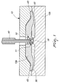
- a check valve particularly for molds of plastic molding machines according to the invention, is generally designated by the reference numeral 10.
- the check valve 10 is constituted by a valve body 11, which is accommodated in a complementarily shaped seat 12 of a mold 13 for plastic material 14.
- the mold 13 is composed substantially of a first mold part 13a and a second mold part 13b.
- the seat 12, in this embodiment of the invention, is located on the first mold part 13a.
- the valve body 11 has an injection channel 15, inside which a flow control element 16 can float freely.
- the flow control element 16 is constituted, in this embodiment, by a ball 16a.
- the ball 16a is arranged between a port 17 for introducing plastic material 14 and containment means 18 that are suitable to prevent its escape from the valve body 11.
- the ball 16a is pushed, during injection, against the containment means 18 by the pressure of the plastic material 14 injected into the injection channel 15, as shown in Figure 2.
- the ball 16a is pressed against a choke 19 of the inlet port 17 of the injection channel 15, so as to obstruct the inlet port 17.
- the containment means 18 form passage openings 21 for the plastic material 14, so as to stop the stroke of the flow control element 16, i.e., the ball 16a, without preventing the flow of the molding material 14.
- the seat 12 of the valve body 11 has a stroke volume 22 that is such as to allow a reversible translational stroke, from the inside outward, of the valve body 11.
- the valve body 11 has a portion 23 that is suitable to abut against first means 25 for stopping the stroke toward the outside of the first mold part 13 a and against second means 26 for stopping the stroke toward the inside of the mold part 13 a.
- the portion 23 suitable for abutment against first and second stop means 25, 26 is provided by a perimetric protrusion 27 that is monolithic with the valve body 11.
- the perimetric protrusion 27 is annular and is arranged at the end of the valve body 11 so as to be monolithic therewith.
- the first stop means 25 are constituted by an abutment ring 30 that is inserted in a corresponding slot 31 provided in the seat 12.
- the second stop means 26 are constituted by a shoulder 33 for transition between the stroke volume 22 and the expansion chamber 24.
- the containment means 18 for the flow control element 16 are constituted by at least three equidistant tabs 34 that are arranged in a co-planar configuration so as to protrude from the internal surface 35 of the injection channel 15.
- the tabs 34 form the passage openings 21 for the plastic material 14.
- valve 10 The operation of the valve 10 is as follows.
- the injector 40 rests against the valve body 11 and injects into the injection channel 15 fluid plastic material 14, which fills the internal channels 41 of the mold 13 and the impressions 50.
- the plastic material 14 can be of the thermosetting type, for example ethyl vinyl acetate.
- valve body 11 in turn is locked in abutment against the shoulder 33 by way of its perimetric protrusion 27.
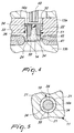
- the injector 40 moves away from the valve body 11 at least beyond the abutment ring 30.
- valve body 11 is free to perform a translational motion up to the abutment ring 30, as shown in Figure 4, by which it is blocked in its motion toward the outside of the mold part 13a.
- the translational motion of the valve body 11 toward the ring 30 makes the expansion chamber 24 available to the expansion of the plastic material 14b.
- the expansion chamber 24 has dimensions that depend on the number and volume of the impressions 50 formed by the mold 13 and is such as to avoid the formation of excessive and disadvantageous sprue 45.
- valve body 11 is returned into abutment against the shoulder 33 by the thrust applied by the injector 40, which rests on the valve body 11.
- the injector 40 is kept in contact with the valve body 11 for a time interval that can be preset according to the number, size and shape of the impressions 50 and according to the amount of plastic material that is injected.
- the injected plastic material by expanding, in fact first blocks the inlet port 17 by pushing the ball 16a against it; then the injector 40, in contact with the valve body 11, prevents said material, for a predefined time interval, from expanding in the expansion chamber 24, so that it can instead penetrate into the impressions 50 in the best possible manner.
- the present invention provides a check valve that allows to optimize the distribution of the plastic material in the various impressions formed by a same mold, producing a uniform pressure inside them.
- the present invention provides a check valve that allows to provide products that are substantially free from flash while minimizing sprue.
- the present invention provides a check valve that can be provided easily and cheaply in known molds.
- the present invention provides a check valve, particularly for molds of plastic molding machines, that can be manufactured with known systems and technologies.
- the materials employed may be any according to requirements and to the state of the art.
Landscapes
- Engineering & Computer Science (AREA)
- Manufacturing & Machinery (AREA)
- Mechanical Engineering (AREA)
- Injection Moulding Of Plastics Or The Like (AREA)
- Check Valves (AREA)
- Moulds For Moulding Plastics Or The Like (AREA)
- Forging (AREA)
- Perforating, Stamping-Out Or Severing By Means Other Than Cutting (AREA)
- Processing And Handling Of Plastics And Other Materials For Molding In General (AREA)
Applications Claiming Priority (2)
| Application Number | Priority Date | Filing Date | Title |
|---|---|---|---|
| ITPD20030302 | 2003-12-17 | ||
| IT000302A ITPD20030302A1 (it) | 2003-12-17 | 2003-12-17 | Valvola di non ritorno, particolarmente per stampi di macchine per lo stampaggio di materia plastica |
Publications (3)
| Publication Number | Publication Date |
|---|---|
| EP1543936A2 true EP1543936A2 (de) | 2005-06-22 |
| EP1543936A3 EP1543936A3 (de) | 2006-03-08 |
| EP1543936B1 EP1543936B1 (de) | 2007-06-27 |
Family
ID=34509491
Family Applications (1)
| Application Number | Title | Priority Date | Filing Date |
|---|---|---|---|
| EP04023034A Expired - Lifetime EP1543936B1 (de) | 2003-12-17 | 2004-09-28 | Rückschlagventil insbesondere für Werkzeuge von Kunststoffverarbeitungsmaschinen |
Country Status (8)
| Country | Link |
|---|---|
| EP (1) | EP1543936B1 (de) |
| KR (1) | KR20050061282A (de) |
| CN (2) | CN2767114Y (de) |
| AT (1) | ATE365621T1 (de) |
| BR (1) | BRPI0404120A (de) |
| DE (1) | DE602004007227D1 (de) |
| IT (1) | ITPD20030302A1 (de) |
| TW (1) | TW200521362A (de) |
Cited By (2)
| Publication number | Priority date | Publication date | Assignee | Title |
|---|---|---|---|---|
| FR2928578A1 (fr) * | 2008-03-11 | 2009-09-18 | Faurecia Interieur Ind Snc | Piece d'equipement de vehicule automobile, et procede de fabrication associe |
| WO2011098395A1 (en) * | 2010-02-11 | 2011-08-18 | Sika Technology Ag | Baffle or reinforcer with fixation mechanism |
Families Citing this family (2)
| Publication number | Priority date | Publication date | Assignee | Title |
|---|---|---|---|---|
| KR101721421B1 (ko) | 2015-05-19 | 2017-03-31 | (주)삼성유압기계 | 2축 연신 블로우 성형장치 및 방법 |
| WO2017142352A1 (ko) * | 2016-02-19 | 2017-08-24 | (주) 디케이 문교 | 체크밸브가 설치된 의치 성형용 플라스크 및 이종재질의 의치 성형용 플라스크를 사용한 의치보조물 제조방법 |
Family Cites Families (4)
| Publication number | Priority date | Publication date | Assignee | Title |
|---|---|---|---|---|
| US3374502A (en) * | 1965-10-12 | 1968-03-26 | Osley & Whitney Inc | Sprue bushing and nozzle assembly |
| CH497262A (de) * | 1969-03-06 | 1970-10-15 | Semperit Ag | Spritzgiessform mit einem Absperrorgan im Einspritzkanal, insbesondere für die Herstellung von Formkörpern aus schaumfähigem Polyurethan |
| JPS4958156A (de) * | 1972-10-06 | 1974-06-05 | ||
| US4213751A (en) * | 1978-06-06 | 1980-07-22 | The Continental Group, Inc. | Valve gate mechanism for injection molding |
-
2003
- 2003-12-17 IT IT000302A patent/ITPD20030302A1/it unknown
-
2004
- 2004-01-27 TW TW093101734A patent/TW200521362A/zh unknown
- 2004-09-28 DE DE602004007227T patent/DE602004007227D1/de not_active Expired - Lifetime
- 2004-09-28 EP EP04023034A patent/EP1543936B1/de not_active Expired - Lifetime
- 2004-09-28 AT AT04023034T patent/ATE365621T1/de not_active IP Right Cessation
- 2004-09-30 BR BR0404120-8A patent/BRPI0404120A/pt not_active IP Right Cessation
- 2004-10-21 KR KR1020040084430A patent/KR20050061282A/ko not_active Ceased
- 2004-12-17 CN CNU2004201166472U patent/CN2767114Y/zh not_active Expired - Fee Related
- 2004-12-17 CN CNA2004101019567A patent/CN1629526A/zh active Pending
Cited By (5)
| Publication number | Priority date | Publication date | Assignee | Title |
|---|---|---|---|---|
| FR2928578A1 (fr) * | 2008-03-11 | 2009-09-18 | Faurecia Interieur Ind Snc | Piece d'equipement de vehicule automobile, et procede de fabrication associe |
| WO2011098395A1 (en) * | 2010-02-11 | 2011-08-18 | Sika Technology Ag | Baffle or reinforcer with fixation mechanism |
| EP2360002A1 (de) * | 2010-02-11 | 2011-08-24 | Sika Technology AG | Dämpfungselement oder Verstärkungselement mit Befestigungselement |
| US20130037152A1 (en) * | 2010-02-11 | 2013-02-14 | Vincent Belpaire | Baffle or reinforcer with fixation mechanism |
| US9744701B2 (en) | 2010-02-11 | 2017-08-29 | Sika Technology Ag | Baffle or reinforcer with fixation mechanism |
Also Published As
| Publication number | Publication date |
|---|---|
| EP1543936B1 (de) | 2007-06-27 |
| BRPI0404120A (pt) | 2005-08-23 |
| DE602004007227D1 (de) | 2007-08-09 |
| ITPD20030302A1 (it) | 2005-06-18 |
| CN2767114Y (zh) | 2006-03-29 |
| ATE365621T1 (de) | 2007-07-15 |
| TW200521362A (en) | 2005-07-01 |
| CN1629526A (zh) | 2005-06-22 |
| EP1543936A3 (de) | 2006-03-08 |
| KR20050061282A (ko) | 2005-06-22 |
Similar Documents
| Publication | Publication Date | Title |
|---|---|---|
| RU2440236C2 (ru) | Изостатический штамп для формования плитки | |
| JP6911245B2 (ja) | プラスチック材料の射出成形のための方法、装置、およびプレス | |
| JP4628476B2 (ja) | 射出成型装置 | |
| CN109605695B (zh) | 一种注塑机多阶段锁模成型的方法 | |
| EP1543936B1 (de) | Rückschlagventil insbesondere für Werkzeuge von Kunststoffverarbeitungsmaschinen | |
| KR101234364B1 (ko) | 압축코어를 이용한 사출압축 성형장치 및 방법 | |
| JP4414801B2 (ja) | 繊維強化プラスチックの成形方法および成形装置 | |
| KR101011842B1 (ko) | 다점게이트 사출성형기에서의 노즐게이트 개폐 타이밍조정기구 | |
| CN103507241A (zh) | 一种较深的杯状类制品的模具的冷却水路结构 | |
| US7998395B2 (en) | Method for injection molding of hollow articles of plastic material | |
| US20070298141A1 (en) | Waste-less injection molding fan gate | |
| US20130171290A1 (en) | Mold-Tool System having Actuator Assembly Including Piston Assembly and Flexible Diaphragm Assembly | |
| CA2528105A1 (en) | Method and device for injecting an injection molded part made of plastic | |
| KR102240758B1 (ko) | 사출기의 노즐장치 | |
| CN115056427A (zh) | 一种压注式哑铃橡胶包胶模具 | |
| CN204263482U (zh) | 注塑机的注射机构 | |
| CN104441510A (zh) | 注塑机的注射机构 | |
| KR101889098B1 (ko) | 표면 함몰 없는 제품의 사출 성형 금형 | |
| KR101933862B1 (ko) | 사출 금형 장치 | |
| KR101760571B1 (ko) | 핫러너 사출금형의 사이드 게이트 밸브장치 및 이를 이용한 사출성형 방법 | |
| KR101533080B1 (ko) | 곡선 유체 유로를 구비한 사출 성형 금형 | |
| JP2019063999A (ja) | 射出成形機用ホットランナユニット | |
| KR0137722Y1 (ko) | 유압 작용식 타일 금형 | |
| KR0140419Y1 (ko) | 가스주입 노즐장치 | |
| KR101868986B1 (ko) | 슬라이드 코어가 있는 다이캐스팅 금형 |
Legal Events
| Date | Code | Title | Description |
|---|---|---|---|
| PUAI | Public reference made under article 153(3) epc to a published international application that has entered the european phase |
Free format text: ORIGINAL CODE: 0009012 |
|
| AK | Designated contracting states |
Kind code of ref document: A2 Designated state(s): AT BE BG CH CY CZ DE DK EE ES FI FR GB GR HU IE IT LI LU MC NL PL PT RO SE SI SK TR |
|
| AX | Request for extension of the european patent |
Extension state: AL HR LT LV MK |
|
| PUAL | Search report despatched |
Free format text: ORIGINAL CODE: 0009013 |
|
| AK | Designated contracting states |
Kind code of ref document: A3 Designated state(s): AT BE BG CH CY CZ DE DK EE ES FI FR GB GR HU IE IT LI LU MC NL PL PT RO SE SI SK TR |
|
| AX | Request for extension of the european patent |
Extension state: AL HR LT LV MK |
|
| 17P | Request for examination filed |
Effective date: 20060726 |
|
| AKX | Designation fees paid |
Designated state(s): AT BE BG CH CY CZ DE DK EE ES FI FR GB GR HU IE IT LI LU MC NL PL PT RO SE SI SK TR |
|
| GRAP | Despatch of communication of intention to grant a patent |
Free format text: ORIGINAL CODE: EPIDOSNIGR1 |
|
| GRAS | Grant fee paid |
Free format text: ORIGINAL CODE: EPIDOSNIGR3 |
|
| GRAA | (expected) grant |
Free format text: ORIGINAL CODE: 0009210 |
|
| RAP1 | Party data changed (applicant data changed or rights of an application transferred) |
Owner name: MAIN GROUP CORPORATION S.R.L. |
|
| AK | Designated contracting states |
Kind code of ref document: B1 Designated state(s): AT BE BG CH CY CZ DE DK EE ES FI FR GB GR HU IE IT LI LU MC NL PL PT RO SE SI SK TR |
|
| REG | Reference to a national code |
Ref country code: GB Ref legal event code: FG4D |
|
| REG | Reference to a national code |
Ref country code: CH Ref legal event code: EP |
|
| REG | Reference to a national code |
Ref country code: IE Ref legal event code: FG4D |
|
| REF | Corresponds to: |
Ref document number: 602004007227 Country of ref document: DE Date of ref document: 20070809 Kind code of ref document: P |
|
| PG25 | Lapsed in a contracting state [announced via postgrant information from national office to epo] |
Ref country code: SE Free format text: LAPSE BECAUSE OF FAILURE TO SUBMIT A TRANSLATION OF THE DESCRIPTION OR TO PAY THE FEE WITHIN THE PRESCRIBED TIME-LIMIT Effective date: 20070927 |
|
| PG25 | Lapsed in a contracting state [announced via postgrant information from national office to epo] |
Ref country code: AT Free format text: LAPSE BECAUSE OF FAILURE TO SUBMIT A TRANSLATION OF THE DESCRIPTION OR TO PAY THE FEE WITHIN THE PRESCRIBED TIME-LIMIT Effective date: 20070627 Ref country code: PL Free format text: LAPSE BECAUSE OF FAILURE TO SUBMIT A TRANSLATION OF THE DESCRIPTION OR TO PAY THE FEE WITHIN THE PRESCRIBED TIME-LIMIT Effective date: 20070627 |
|
| PGFP | Annual fee paid to national office [announced via postgrant information from national office to epo] |
Ref country code: TR Payment date: 20070925 Year of fee payment: 4 |
|
| NLV1 | Nl: lapsed or annulled due to failure to fulfill the requirements of art. 29p and 29m of the patents act | ||
| REG | Reference to a national code |
Ref country code: CH Ref legal event code: PL |
|
| PG25 | Lapsed in a contracting state [announced via postgrant information from national office to epo] |
Ref country code: BE Free format text: LAPSE BECAUSE OF FAILURE TO SUBMIT A TRANSLATION OF THE DESCRIPTION OR TO PAY THE FEE WITHIN THE PRESCRIBED TIME-LIMIT Effective date: 20070627 |
|
| PG25 | Lapsed in a contracting state [announced via postgrant information from national office to epo] |
Ref country code: PT Free format text: LAPSE BECAUSE OF FAILURE TO SUBMIT A TRANSLATION OF THE DESCRIPTION OR TO PAY THE FEE WITHIN THE PRESCRIBED TIME-LIMIT Effective date: 20071127 Ref country code: SI Free format text: LAPSE BECAUSE OF FAILURE TO SUBMIT A TRANSLATION OF THE DESCRIPTION OR TO PAY THE FEE WITHIN THE PRESCRIBED TIME-LIMIT Effective date: 20070627 Ref country code: ES Free format text: LAPSE BECAUSE OF FAILURE TO SUBMIT A TRANSLATION OF THE DESCRIPTION OR TO PAY THE FEE WITHIN THE PRESCRIBED TIME-LIMIT Effective date: 20071008 Ref country code: NL Free format text: LAPSE BECAUSE OF FAILURE TO SUBMIT A TRANSLATION OF THE DESCRIPTION OR TO PAY THE FEE WITHIN THE PRESCRIBED TIME-LIMIT Effective date: 20070627 Ref country code: CZ Free format text: LAPSE BECAUSE OF FAILURE TO SUBMIT A TRANSLATION OF THE DESCRIPTION OR TO PAY THE FEE WITHIN THE PRESCRIBED TIME-LIMIT Effective date: 20070627 Ref country code: BG Free format text: LAPSE BECAUSE OF FAILURE TO SUBMIT A TRANSLATION OF THE DESCRIPTION OR TO PAY THE FEE WITHIN THE PRESCRIBED TIME-LIMIT Effective date: 20070927 |
|
| EN | Fr: translation not filed | ||
| PG25 | Lapsed in a contracting state [announced via postgrant information from national office to epo] |
Ref country code: CH Free format text: LAPSE BECAUSE OF FAILURE TO SUBMIT A TRANSLATION OF THE DESCRIPTION OR TO PAY THE FEE WITHIN THE PRESCRIBED TIME-LIMIT Effective date: 20070627 Ref country code: SK Free format text: LAPSE BECAUSE OF FAILURE TO SUBMIT A TRANSLATION OF THE DESCRIPTION OR TO PAY THE FEE WITHIN THE PRESCRIBED TIME-LIMIT Effective date: 20070627 Ref country code: LI Free format text: LAPSE BECAUSE OF FAILURE TO SUBMIT A TRANSLATION OF THE DESCRIPTION OR TO PAY THE FEE WITHIN THE PRESCRIBED TIME-LIMIT Effective date: 20070627 |
|
| PG25 | Lapsed in a contracting state [announced via postgrant information from national office to epo] |
Ref country code: DK Free format text: LAPSE BECAUSE OF FAILURE TO SUBMIT A TRANSLATION OF THE DESCRIPTION OR TO PAY THE FEE WITHIN THE PRESCRIBED TIME-LIMIT Effective date: 20070627 Ref country code: MC Free format text: LAPSE BECAUSE OF NON-PAYMENT OF DUE FEES Effective date: 20070930 Ref country code: DE Free format text: LAPSE BECAUSE OF FAILURE TO SUBMIT A TRANSLATION OF THE DESCRIPTION OR TO PAY THE FEE WITHIN THE PRESCRIBED TIME-LIMIT Effective date: 20070928 Ref country code: GR Free format text: LAPSE BECAUSE OF FAILURE TO SUBMIT A TRANSLATION OF THE DESCRIPTION OR TO PAY THE FEE WITHIN THE PRESCRIBED TIME-LIMIT Effective date: 20070928 |
|
| PLBE | No opposition filed within time limit |
Free format text: ORIGINAL CODE: 0009261 |
|
| STAA | Information on the status of an ep patent application or granted ep patent |
Free format text: STATUS: NO OPPOSITION FILED WITHIN TIME LIMIT |
|
| PG25 | Lapsed in a contracting state [announced via postgrant information from national office to epo] |
Ref country code: RO Free format text: LAPSE BECAUSE OF FAILURE TO SUBMIT A TRANSLATION OF THE DESCRIPTION OR TO PAY THE FEE WITHIN THE PRESCRIBED TIME-LIMIT Effective date: 20070627 |
|
| 26N | No opposition filed |
Effective date: 20080328 |
|
| PG25 | Lapsed in a contracting state [announced via postgrant information from national office to epo] |
Ref country code: FR Free format text: LAPSE BECAUSE OF FAILURE TO SUBMIT A TRANSLATION OF THE DESCRIPTION OR TO PAY THE FEE WITHIN THE PRESCRIBED TIME-LIMIT Effective date: 20080222 |
|
| PG25 | Lapsed in a contracting state [announced via postgrant information from national office to epo] |
Ref country code: IE Free format text: LAPSE BECAUSE OF NON-PAYMENT OF DUE FEES Effective date: 20070928 |
|
| PG25 | Lapsed in a contracting state [announced via postgrant information from national office to epo] |
Ref country code: EE Free format text: LAPSE BECAUSE OF FAILURE TO SUBMIT A TRANSLATION OF THE DESCRIPTION OR TO PAY THE FEE WITHIN THE PRESCRIBED TIME-LIMIT Effective date: 20070627 |
|
| PG25 | Lapsed in a contracting state [announced via postgrant information from national office to epo] |
Ref country code: FI Free format text: LAPSE BECAUSE OF FAILURE TO SUBMIT A TRANSLATION OF THE DESCRIPTION OR TO PAY THE FEE WITHIN THE PRESCRIBED TIME-LIMIT Effective date: 20070627 |
|
| PGFP | Annual fee paid to national office [announced via postgrant information from national office to epo] |
Ref country code: IT Payment date: 20080929 Year of fee payment: 5 |
|
| GBPC | Gb: european patent ceased through non-payment of renewal fee |
Effective date: 20080928 |
|
| PG25 | Lapsed in a contracting state [announced via postgrant information from national office to epo] |
Ref country code: CY Free format text: LAPSE BECAUSE OF FAILURE TO SUBMIT A TRANSLATION OF THE DESCRIPTION OR TO PAY THE FEE WITHIN THE PRESCRIBED TIME-LIMIT Effective date: 20070627 |
|
| PG25 | Lapsed in a contracting state [announced via postgrant information from national office to epo] |
Ref country code: LU Free format text: LAPSE BECAUSE OF NON-PAYMENT OF DUE FEES Effective date: 20070928 |
|
| PG25 | Lapsed in a contracting state [announced via postgrant information from national office to epo] |
Ref country code: HU Free format text: LAPSE BECAUSE OF FAILURE TO SUBMIT A TRANSLATION OF THE DESCRIPTION OR TO PAY THE FEE WITHIN THE PRESCRIBED TIME-LIMIT Effective date: 20071228 |
|
| PG25 | Lapsed in a contracting state [announced via postgrant information from national office to epo] |
Ref country code: GB Free format text: LAPSE BECAUSE OF NON-PAYMENT OF DUE FEES Effective date: 20080928 |
|
| PG25 | Lapsed in a contracting state [announced via postgrant information from national office to epo] |
Ref country code: IT Free format text: LAPSE BECAUSE OF NON-PAYMENT OF DUE FEES Effective date: 20090928 |
|
| PG25 | Lapsed in a contracting state [announced via postgrant information from national office to epo] |
Ref country code: TR Free format text: LAPSE BECAUSE OF NON-PAYMENT OF DUE FEES Effective date: 20100921 |
|
| PG25 | Lapsed in a contracting state [announced via postgrant information from national office to epo] |
Ref country code: TR Free format text: LAPSE BECAUSE OF NON-PAYMENT OF DUE FEES Effective date: 20080928 |