EP1543997A1 - Optimierte Felge und Rad mit solcher Felge - Google Patents
Optimierte Felge und Rad mit solcher Felge Download PDFInfo
- Publication number
- EP1543997A1 EP1543997A1 EP04292766A EP04292766A EP1543997A1 EP 1543997 A1 EP1543997 A1 EP 1543997A1 EP 04292766 A EP04292766 A EP 04292766A EP 04292766 A EP04292766 A EP 04292766A EP 1543997 A1 EP1543997 A1 EP 1543997A1
- Authority
- EP
- European Patent Office
- Prior art keywords
- rim
- point
- curvature
- wheel
- points
- Prior art date
- Legal status (The legal status is an assumption and is not a legal conclusion. Google has not performed a legal analysis and makes no representation as to the accuracy of the status listed.)
- Granted
Links
Images


Classifications
-
- B—PERFORMING OPERATIONS; TRANSPORTING
- B60—VEHICLES IN GENERAL
- B60B—VEHICLE WHEELS; CASTORS; AXLES FOR WHEELS OR CASTORS; INCREASING WHEEL ADHESION
- B60B3/00—Disc wheels, i.e. wheels with load-supporting disc body
- B60B3/04—Disc wheels, i.e. wheels with load-supporting disc body with a single disc body not integral with rim, i.e. disc body and rim being manufactured independently and then permanently attached to each other in a second step, e.g. by welding
- B60B3/041—Disc wheels, i.e. wheels with load-supporting disc body with a single disc body not integral with rim, i.e. disc body and rim being manufactured independently and then permanently attached to each other in a second step, e.g. by welding characterised by the attachment of rim to wheel disc
- B60B3/044—Disc wheels, i.e. wheels with load-supporting disc body with a single disc body not integral with rim, i.e. disc body and rim being manufactured independently and then permanently attached to each other in a second step, e.g. by welding characterised by the attachment of rim to wheel disc characterised by cross-sectional details of the attachment, e.g. the profile
-
- B—PERFORMING OPERATIONS; TRANSPORTING
- B60—VEHICLES IN GENERAL
- B60B—VEHICLE WHEELS; CASTORS; AXLES FOR WHEELS OR CASTORS; INCREASING WHEEL ADHESION
- B60B21/00—Rims
- B60B21/02—Rims characterised by transverse section
- B60B21/026—Rims characterised by transverse section the shape of rim well
-
- B—PERFORMING OPERATIONS; TRANSPORTING
- B60—VEHICLES IN GENERAL
- B60B—VEHICLE WHEELS; CASTORS; AXLES FOR WHEELS OR CASTORS; INCREASING WHEEL ADHESION
- B60B21/00—Rims
- B60B21/02—Rims characterised by transverse section
- B60B21/028—Rims characterised by transverse section the shape of hump
-
- B—PERFORMING OPERATIONS; TRANSPORTING
- B60—VEHICLES IN GENERAL
- B60B—VEHICLE WHEELS; CASTORS; AXLES FOR WHEELS OR CASTORS; INCREASING WHEEL ADHESION
- B60B21/00—Rims
- B60B21/02—Rims characterised by transverse section
- B60B21/04—Rims characterised by transverse section with substantially radial flanges
-
- B—PERFORMING OPERATIONS; TRANSPORTING
- B60—VEHICLES IN GENERAL
- B60B—VEHICLE WHEELS; CASTORS; AXLES FOR WHEELS OR CASTORS; INCREASING WHEEL ADHESION
- B60B3/00—Disc wheels, i.e. wheels with load-supporting disc body
- B60B3/02—Disc wheels, i.e. wheels with load-supporting disc body with a single disc body integral with rim
Definitions
- the present invention relates to a rim for a wheel of a motor vehicle. More particularly, the invention relates to a rim allowing the assembly and the use of a tire without bedroom. More particularly, the invention relates to a rim in one piece of sheet metal. It should be noted that the invention does not apply to the field of light alloy wheels obtained by molding and / or forging.
- a wheel consists essentially of a rim and a sail, also called disc, which can be attached directly or indirectly to a hub.
- the rim has a form of revolution around a main axis corresponding to the axis of the wheel.
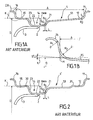
- Figure 1A appended drawings partially represent the axial section, or meridian section, a wheel according to the prior art.
- the right K is parallel to the main axis of the wheel and is located at a distance D of it.
- the right part of a figure corresponds to side of the wheel, or the rim, intended to be positioned on the side of the car body and will be qualified interior side.
- the left side of a figure corresponds to the side of the wheel, or the rim, intended to be positioned away from the vehicle body and will be qualified on the outside.
- the line K can therefore be oriented from the inside towards the outside.
- the radially outer face of the rim, or profile of the rim has an inner hook portion 11, a portion forming an inner seat 12, a connecting part 13, a shaped part groove 14, an outer seat portion 15 and a portion forming outside hook 16.
- the rim 1 has a diameter D and a width A, as defined by the ETRTO standard. More specifically with reference to FIG. 1B, a straight line tangent to the outer seat portion 15 intersects at a point M a vertical line tangent to the circle of radius R 2 connecting the outer seat portion 15 and the outer hook portion 16.
- the line K is then defined as the line parallel to the main axis of the wheel, generally horizontal, passing through the point M.
- the diameter D of the rim is equal to twice the distance between the main axis of the wheel and the straight line K. It should be noted that the line tangent to the outer seat part 15 makes a slight angle of 5 ° with the line K.
- the width A of the rim is defined as the distance between a first vertical straight line tangent to the circle of radius R 2 connecting the outer seat portion 15 and the outer hook portion 16 and a second vertical straight tangent to the circle of radius R 2 connecting the inner seat portion 12 and the crocheting portion domestic chet 11.
- the groove portion 14 has an inner flank 21, a bottom 22 and an outer flank 23.
- the bottom 22 is in depression relative to the outer seat portion 15 of a depth at least equal to a predefined minimum depth H min .
- the bottom 22 thus has a maximum diameter given by the formula D-2H min .
- the function of the groove portion 14 is to allow the mounting of a tubeless tire in an otherwise known manner.
- the sheet metal veil 3 has a part globally cylindrical axis device the main axis.
- the face radially inner bottom 22 is welded to the peripheral portion of the sail, or edge, by one or more weld seams 2: either the welding is carried out by a single continuous weld seam, ie the welding is carried out by a plurality of weld seams 2.
- the welding beads 2 are distributed annularly regularly every 90 °, and extend respectively on an opening arc at the top of 30 °.
- the weld discontinuous having a plurality of cords, has the advantage to save the material needed to achieve the welding and to reduce the welding time, especially if one simultaneously the different cords using separate welding torches. She is especially easier to achieve when the edge of the soldering disc presents an irregular geometry related to its realization process (Drawing).
- Figure 2 of the attached drawings represents a other rim the according to the prior art.
- the profile of this other rim is essentially identical to that of the rim 1 shown in FIG. but additionally has an anti-decoupling boss portion interior 31 connecting the inner seat portion 12 and the portion of link 13, and an outer anti-decoupling boss portion connecting the outer flank 23 of the throat portion 14 and the portion 15.
- the presence of the boss parts inner and outer 31, 32 allow the parts forming a seat outside and inside to define bowls in which the heels inside and outside of the tire are respectively positioned at force by crossing the bosses.
- the ETRTO standard defines standard rim profiles by giving a number of dimensions: diameter of the rim D, width A, minimum depth of the groove-shaped part H min (for example 15 mm or 17.3 mm d 'after the norm), sloping seat parts etc.
- the shape of the inner side of the throat portion is not part of this standard and is left to the choice of the manufacturer of the rim. The latter must take into account the size of the elements that must be positioned radially inside the rim, such as the elements of the brake system such as the brake disc and the brake caliper.
- the invention therefore aims to propose a rim improved enabling discontinuous welding by means of a plurality of weld seams but less prone to the appearance of cracks.
- the subject of the invention is a sheet metal rim for a motor vehicle wheel, having a shape of revolution about a main axis corresponding to the axis of rotation of the wheel, the rim having, in a meridian plane, a profile radially outside the rim having, from an inner side of the rim intended to be placed on the side of the vehicle body towards an outer side of the rim intended to be placed away from the vehicle body, an inner hook part, a part forming an inner seat, a connecting portion, a groove-shaped portion, an outer seat portion, and an outer hook portion, the groove-shaped portion having an inner flank connected to said connecting portion, a bottom and a outer flank, the rim having a predetermined diameter D and width A and the groove portion having, relative to said diameter, a depth at least equal to a minimum depth H mi n predefined, characterized in that, considering that a curvature of the profile of the inner flank is strictly positive at a point when the center of curvature at this point is disposed at a fi
- the inner flank includes, extending between the first point and the second point, a single curve segment with a strictly positive curvature in all points.
- the inner flank comprises a plurality of segments of curve having a curvature strictly positive in all points.
- At least two of the plurality segments of curve segments having a strictly positive curvature in all points are connected to each other by at least one curve segment intermediate.
- the at least one segment of intermediate curve is a straight intermediate curve segment having in all points a null curvature.
- said at least one intermediate curve segment is an intermediate curve segment having a strictly negative curvature in all points.
- the radius of curvature at any point of said at least one curve segment having a strictly positive curvature in all points is greater than a predefined radius of curvature R 0 .
- the predefined radius of curvature is 20 mm.
- the profile comprises a portion forming internal anti-decoupling boss between said seat portion interior and said connecting portion, and an anti-decoupling boss portion between said outer seat portion and said outer flank of said throat-shaped portion, the parts forming an inner and outer boss respectively having a diameter strictly greater than the diameter of said inner seat parts and outside.
- the invention also relates to a wheel for a vehicle automobile having a sail and a sheet metal rim, said sail being welded by a plurality of radially seam weld seams interior of a throat-shaped portion of the rim, characterized in that that the rim is a rim according to what has been described above.
- the applicant has carried out numerical simulations as well that tests to define a rim with a particular profile for which the mechanical stresses generated at the ends circumferential weld seams are correctly distributed and dissipated.
- the first embodiment of the rim according to the invention will be described in detail with reference to FIG. 3.
- the groove portion 114 of the rim 101 has an inner flank 125 connecting the bottom 22 of the groove portion 114. and the connecting portion 13.
- the inner side 125 has a strictly positive curvature curve segment 125+, extending between a first point A 0 and a second point B 0 , and a negative curvature curve segment 125-, extending from the second point B 0 to the connecting portion 13.
- curvature When moving along the profile of the rim, on the inside towards the outside or from the outside to the inside, and that the center of curvature of the profile at a point is located radially at the outside of the wheel rim, the curvature will be said positive. Conversely, when the center of curvature is located radially at inside the rim, the curvature will be called negative. So equivalent, a segment of positive curvature curve is a segment curve having a concavity oriented radially outwardly of the rim. A segment of negative curvature curve is a segment of curve having a convexity oriented radially outwardly of the rim. The curvature being equal to the inverse of the radius of curvature, it will be zero in the case of a rectilinear curve segment.
- a curve segment is implicitly defined as a portion of curve for which the curvature is a continuously varying function. At a point where the curvature is discontinuous, the profile has a sharp angle. A segment of curve is therefore limited by two points. For each of these points, the curvature undergoes a discontinuity either the curvature vanishes or changes sign.
- the strictly positive curvature segment 125+ extends between the point A 0 and the point B 0 .
- the first point A 0 is defined as the point of the inner side 125 which is adjacent to the bottom 22 and which is positioned radially on a circle of diameter D-2H min .
- the second point B 0 is defined as the last point of the inner side 125, when moving from A 0 to B 0 , having a strictly positive curvature.
- the strictly positive curvature curve segment 125+ is unique between the points A 0 and B 0 and extends from the point A 0 to the point B 0 .
- the projection on the main axis, or on the line K, of the strictly positive curvature curve segment 125+ has a length L.
- the length L is greater than a predetermined length L 0 .
- the predetermined length is identical regardless of the diameter D and the width A of the rim considered and is 15 mm.
- the positive curvature curve segment 125+ has a smooth evolution. Specifically, the radius of curvature at any point within the positive curvature curve segment 125+ is greater than a predefined radius of curvature R 0 .
- the predefined radius of curvature R 0 is preferably 20 mm.
- FIG. 4 a second embodiment is represent.
- the rim 201 of this second embodiment is essentially identical to that of the first embodiment shown in Figure 3, in particular with regard to the part in throat shape which is therefore identified by means of the same figure of reference 114.
- This second embodiment differs from the previous only by the presence of an anti-decoupling boss portion interior 31 and an outer anti-decoupling boss portion Identical to those described in the introductory part of this document with reference to FIG.
- Figure 5 shows a third embodiment of the rim according to the invention.
- the rim 301 of this embodiment is close to the rim according to the second embodiment of Figure 4 in that it has anti-decoupling boss portions.
- the inner flank 325 of the groove portion 314 has a single curve segment 325 + having a concavity oriented radially outwardly of the rim between the first point A 0 and the second point B0 a straight curve segment 325 0 of zero curvature between the second point B 0 and a third point C 0 , and a curve segment 325 having a convexity oriented radially outwardly of the rim of the point C 0 to the connecting part 13.
- the third point C 0 can be defined as the point of the inner side 325 which, when moving from the first point A 0 to the connecting part 13, is the first point having a strictly negative curvature .
- the strictly positive curvature curve segment 325+ is unique between the points A 0 and B 0 and extends from A 0 to Bo.
- FIG. 6 a fourth embodiment is presented in which, between a first point A 1 and a second point B 3 , the inner side 425 of the rim 401 has a plurality of strictly positive curvature curve segments.
- the segments of curve of strictly positive curvature are connected to each other by intermediate curve segments which are in this particular embodiment of intermediate curve segments of strictly negative curvature forming bosses.
- a first strictly positive curvature curve segment 425 1 extends from the first point A 1 to the point B 1
- a first projection 426 forming an intermediate curve segment of strictly negative curvature, extends between the point B 1 and the point A 2
- a second segment of curve of strictly positive curvature 425 2 extends from the point A 2 to the point B 2
- a second boss 427 forming a second intermediate curve segment of strictly negative curvature, extends between the point B 2 and the point A 3
- a third segment of strictly positive curvature 425 3 extends between the point A 3 and the second point B 3 .
- the first point A 1 can be defined, like the first point A 0 of FIG. 3, as the point of the inner side 425 which is adjacent to the bottom 22 and which is positioned radially on a circle of diameter D-2H min. .
- the second point B 3 can be defined, like the second point B 0 of Figure 3, as the last point of the inner side 425 having a strictly positive curvature.
- the intermediate points B 1 , A 2 , B 2 and A 3 are here discontinuity points of the curvature.
- the geometric condition which has been identified so that no cracks appear in the wall of the bottom 22 of the groove portion 414 is reflected here, as previously, by a condition on the length L between the respective projections on the main axis of the first point A 1 and the second point B 3 .
- the length L must be greater than the predetermined length L 0 of 15 mm.
- the number and the type intermediate curve segments (two in the case of FIG. 6) is not limiting.
- These intermediate curve segments can be rectilinear curve segments whose curvature in all points is nothing.
- the plurality of intermediate curve segments can consist of straight curve segments and segments of curve with strictly negative curvature.
- the points intermediaries are defined by points for which either the curvature undergoes a discontinuity or the curvature vanishes or changes sign.
- the additional condition on the radii of curvature can be applied respectively to the different segments of the plurality of segments of positive curvature curve so that the latter have slow variations: the value of the radius of curvature in all points of the profile belonging to one of the segments of positive curvature curve is greater than a predefined radius of curvature R 0 is preferably 20 mm.
- the rim according to the invention can be welded to a sail of wheel by discontinuous welding performed by means of a plurality of weld seams.
- the resulting wheel has a longer life long as the life of the wheels according to the prior art.
- the profile of the rim according to the invention is easy to obtain for example by a method of rolling a sheet of steel or aluminum. It suffices for that to modify the shape of the tools used for this operation so that they generate the profile of the rim according to the invention.
Landscapes
- Engineering & Computer Science (AREA)
- Mechanical Engineering (AREA)
- Butt Welding And Welding Of Specific Article (AREA)
- Shaping Metal By Deep-Drawing, Or The Like (AREA)
- Tires In General (AREA)
- Laminated Bodies (AREA)
- Arrangement Or Mounting Of Propulsion Units For Vehicles (AREA)
- Turbine Rotor Nozzle Sealing (AREA)
Applications Claiming Priority (2)
| Application Number | Priority Date | Filing Date | Title |
|---|---|---|---|
| FR0314830A FR2863940B1 (fr) | 2003-12-17 | 2003-12-17 | Jante amelioree et roue comportant une telle jante |
| FR0314830 | 2003-12-17 |
Publications (2)
| Publication Number | Publication Date |
|---|---|
| EP1543997A1 true EP1543997A1 (de) | 2005-06-22 |
| EP1543997B1 EP1543997B1 (de) | 2008-03-26 |
Family
ID=34508686
Family Applications (1)
| Application Number | Title | Priority Date | Filing Date |
|---|---|---|---|
| EP04292766A Expired - Lifetime EP1543997B1 (de) | 2003-12-17 | 2004-11-24 | Optimierte Felge und Rad mit solcher Felge |
Country Status (5)
| Country | Link |
|---|---|
| EP (1) | EP1543997B1 (de) |
| AT (1) | ATE390296T1 (de) |
| DE (1) | DE602004012697T2 (de) |
| ES (1) | ES2301951T3 (de) |
| FR (1) | FR2863940B1 (de) |
Cited By (6)
| Publication number | Priority date | Publication date | Assignee | Title |
|---|---|---|---|---|
| GB2431141A (en) * | 2005-10-12 | 2007-04-18 | Gkn Offhighway Systems Ltd | Wheel construction |
| EP2106927A1 (de) | 2008-04-04 | 2009-10-07 | GKN OffHighway Limited | Radaufbau |
| CN102245398A (zh) * | 2008-12-02 | 2011-11-16 | Gkn陆地系统有限公司 | 车轮构造 |
| WO2024134136A1 (en) * | 2022-12-23 | 2024-06-27 | Titan Steel Wheels Limited | Single piece wheel rim and manufacturing method |
| US20240375433A1 (en) * | 2023-05-08 | 2024-11-14 | Maxion Wheels Holding Gmbh | Vehicle wheel rim, vehicle wheel including such a wheel rim and method for producing such a wheel rim and vehicle wheel |
| US20240375432A1 (en) * | 2023-05-08 | 2024-11-14 | Maxion Wheels Holding Gmbh | Vehicle wheel rim, vehicle wheel including such a wheel rim and method for producing such a wheel rim and vehicle wheel |
Families Citing this family (1)
| Publication number | Priority date | Publication date | Assignee | Title |
|---|---|---|---|---|
| DE102015205863B4 (de) * | 2015-04-01 | 2024-12-24 | Ford Global Technologies, Llc | Radfelge mit einem Tiefbett |
Citations (5)
| Publication number | Priority date | Publication date | Assignee | Title |
|---|---|---|---|---|
| DE4006374A1 (de) * | 1990-03-01 | 1991-09-05 | Bcw Kraftfahrzeugtechnik Ag | Neue kontur einer 7 zoll breiten felge fuer kraftfahrzeuge |
| EP0573162A1 (de) * | 1992-06-03 | 1993-12-08 | Bridgestone Corporation | Räder für Luftreifen |
| EP0799721A1 (de) * | 1996-04-02 | 1997-10-08 | COMPAGNIE GENERALE DES ETABLISSEMENTS MICHELIN-MICHELIN & CIE | Rad für Fahrzeuge |
| WO2000026039A1 (en) * | 1998-11-02 | 2000-05-11 | The Goodyear Tire & Rubber Company | A tire and rim assembly |
| FR2808479A3 (fr) * | 2000-05-03 | 2001-11-09 | Michelin Soc Tech | Roue de vehicule utilitaire a valve debouchant a l'exterieur du disque |
-
2003
- 2003-12-17 FR FR0314830A patent/FR2863940B1/fr not_active Expired - Lifetime
-
2004
- 2004-11-24 EP EP04292766A patent/EP1543997B1/de not_active Expired - Lifetime
- 2004-11-24 AT AT04292766T patent/ATE390296T1/de active
- 2004-11-24 DE DE602004012697T patent/DE602004012697T2/de not_active Expired - Lifetime
- 2004-11-24 ES ES04292766T patent/ES2301951T3/es not_active Expired - Lifetime
Patent Citations (5)
| Publication number | Priority date | Publication date | Assignee | Title |
|---|---|---|---|---|
| DE4006374A1 (de) * | 1990-03-01 | 1991-09-05 | Bcw Kraftfahrzeugtechnik Ag | Neue kontur einer 7 zoll breiten felge fuer kraftfahrzeuge |
| EP0573162A1 (de) * | 1992-06-03 | 1993-12-08 | Bridgestone Corporation | Räder für Luftreifen |
| EP0799721A1 (de) * | 1996-04-02 | 1997-10-08 | COMPAGNIE GENERALE DES ETABLISSEMENTS MICHELIN-MICHELIN & CIE | Rad für Fahrzeuge |
| WO2000026039A1 (en) * | 1998-11-02 | 2000-05-11 | The Goodyear Tire & Rubber Company | A tire and rim assembly |
| FR2808479A3 (fr) * | 2000-05-03 | 2001-11-09 | Michelin Soc Tech | Roue de vehicule utilitaire a valve debouchant a l'exterieur du disque |
Cited By (17)
| Publication number | Priority date | Publication date | Assignee | Title |
|---|---|---|---|---|
| US9662935B2 (en) | 2005-10-12 | 2017-05-30 | Gkn Land Systems Limited | Wheel construction |
| JP2009511344A (ja) * | 2005-10-12 | 2009-03-19 | ジーケイエヌ オフハイウェイ システムズ リミテッド | ホイール構造 |
| GB2431141B (en) * | 2005-10-12 | 2009-07-29 | Gkn Offhighway Systems Ltd | Wheel construction |
| US10105987B2 (en) | 2005-10-12 | 2018-10-23 | Gkn Wheels Limited | Wheel construction |
| GB2431141A (en) * | 2005-10-12 | 2007-04-18 | Gkn Offhighway Systems Ltd | Wheel construction |
| CN101287614B (zh) * | 2005-10-12 | 2011-05-25 | Gkn奥弗海威系统有限公司 | 轮结构 |
| WO2009122135A1 (en) * | 2008-04-04 | 2009-10-08 | Gkn Offhighway Limited | Wheel construction |
| CN101990501B (zh) * | 2008-04-04 | 2013-04-17 | Gkn陆地系统有限公司 | 车轮构造 |
| RU2486064C2 (ru) * | 2008-04-04 | 2013-06-27 | Джи Кей Эн Лэнд Системз Лимитид | Конструкция колеса |
| US8991938B2 (en) | 2008-04-04 | 2015-03-31 | Gkn Land Systems Limited | Wheel construction |
| EP2106927A1 (de) | 2008-04-04 | 2009-10-07 | GKN OffHighway Limited | Radaufbau |
| CN102245398B (zh) * | 2008-12-02 | 2014-09-10 | Gkn陆地系统有限公司 | 车轮构造 |
| CN102245398A (zh) * | 2008-12-02 | 2011-11-16 | Gkn陆地系统有限公司 | 车轮构造 |
| WO2024134136A1 (en) * | 2022-12-23 | 2024-06-27 | Titan Steel Wheels Limited | Single piece wheel rim and manufacturing method |
| GB2625793A (en) * | 2022-12-23 | 2024-07-03 | Titan Steel Wheels Ltd | Single piece wheel rim and manufacturing method |
| US20240375433A1 (en) * | 2023-05-08 | 2024-11-14 | Maxion Wheels Holding Gmbh | Vehicle wheel rim, vehicle wheel including such a wheel rim and method for producing such a wheel rim and vehicle wheel |
| US20240375432A1 (en) * | 2023-05-08 | 2024-11-14 | Maxion Wheels Holding Gmbh | Vehicle wheel rim, vehicle wheel including such a wheel rim and method for producing such a wheel rim and vehicle wheel |
Also Published As
| Publication number | Publication date |
|---|---|
| FR2863940B1 (fr) | 2006-02-24 |
| EP1543997B1 (de) | 2008-03-26 |
| ES2301951T3 (es) | 2008-07-01 |
| DE602004012697D1 (de) | 2008-05-08 |
| DE602004012697T2 (de) | 2009-04-16 |
| FR2863940A1 (fr) | 2005-06-24 |
| ATE390296T1 (de) | 2008-04-15 |
Similar Documents
| Publication | Publication Date | Title |
|---|---|---|
| EP0579525B1 (de) | Verfahren zur Herstellung einer Fahrradfelge und nach diesem Verfahren hergestellte Felge | |
| EP1097823B1 (de) | Felge zur Aufnahme eines Stützringes | |
| EP0799722A1 (de) | Rad für Motorfahrzeuge und Verfahren zu dessen Herstellung | |
| WO2018007751A1 (fr) | Anneau-enjoliveur pour une roue pour un pneumatique | |
| EP1543997B1 (de) | Optimierte Felge und Rad mit solcher Felge | |
| EP2316663A1 (de) | Radfelge mit Speichen, damit ausgestattete montierte Einheit und Zusammenbauverfahren | |
| FR2705282A1 (fr) | Dispositif de fixation d'un essieu sur un bras de suspension et procédé de fixation d'un essieu sur un bras de suspension. | |
| FR2744953A1 (fr) | Jante de roue a rayons destinee a etre equipee d'un pneumatique sans chambre, et roue a rayons ainsi equipee | |
| FR2818585A1 (fr) | Ensemble d'une jante et d'un appui de soutien | |
| FR2707559A1 (fr) | Perfectionnement pour roue destinée à équiper les cycles. | |
| EP3572238B1 (de) | Nabe für ein fahrradrad | |
| EP1299251A1 (de) | Fahrzeugrad zusammengesetzt unter dem rand der felge | |
| FR2883612A1 (fr) | Dispositif d'amortissement a flux croises a deux couvercles sans indexage | |
| EP0170085A1 (de) | Sicherheitsfelge mit axialem Blockierhump und mit genannter Felge versehene Luftreifenfelgenanordnung | |
| EP2841774B1 (de) | Element zur befestigung eines zubehörteils an einer halterung und der halterung an einer struktur | |
| EP0484215B1 (de) | Druckfedernspanner | |
| FR2582586A1 (fr) | Roue en alliage leger pour vehicule, dont la jante est constituee d'au moins deux couronnes associees l'une a l'autre en continu et procede pour la fabrication d'une telle roue | |
| FR2722735A1 (fr) | 1roue pour cycle dont les rayons son2l'intermediaire d'une piece indepen | |
| EP1551648B1 (de) | Aus zwei montierten konstruktionen bestehende radfelge | |
| EP1347871B1 (de) | Herstellung eines sekundärkolbens für einen hauptzylinder | |
| FR2989631A1 (fr) | Roue en tole d'aluminium pour vehicule | |
| FR3038672A1 (fr) | Piece de centrage pour un roulement de roue, roulement et assemblage de roue de vehicule associes | |
| WO2019020898A1 (fr) | Roue pour le montage d'un dispositif de type pneumatique pour vehicule | |
| EP1981722A1 (de) | Reifen mit ungleichen sitzdurchmessern und umgekehrtem versatz in aufgepumptem zustand | |
| FR2533864A1 (fr) | Jante de securite pour pneumatiques |
Legal Events
| Date | Code | Title | Description |
|---|---|---|---|
| PUAI | Public reference made under article 153(3) epc to a published international application that has entered the european phase |
Free format text: ORIGINAL CODE: 0009012 |
|
| AK | Designated contracting states |
Kind code of ref document: A1 Designated state(s): AT BE BG CH CY CZ DE DK EE ES FI FR GB GR HU IE IS IT LI LU MC NL PL PT RO SE SI SK TR |
|
| AX | Request for extension of the european patent |
Extension state: AL HR LT LV MK YU |
|
| 17P | Request for examination filed |
Effective date: 20050430 |
|
| AKX | Designation fees paid |
Designated state(s): AT BE BG CH CY CZ DE DK EE ES FI FR GB GR HU IE IS IT LI LU MC NL PL PT RO SE SI SK TR |
|
| RAP1 | Party data changed (applicant data changed or rights of an application transferred) |
Owner name: MEFRO ROUES FRANCE |
|
| GRAP | Despatch of communication of intention to grant a patent |
Free format text: ORIGINAL CODE: EPIDOSNIGR1 |
|
| GRAS | Grant fee paid |
Free format text: ORIGINAL CODE: EPIDOSNIGR3 |
|
| GRAA | (expected) grant |
Free format text: ORIGINAL CODE: 0009210 |
|
| AK | Designated contracting states |
Kind code of ref document: B1 Designated state(s): AT BE BG CH CY CZ DE DK EE ES FI FR GB GR HU IE IS IT LI LU MC NL PL PT RO SE SI SK TR |
|
| REG | Reference to a national code |
Ref country code: GB Ref legal event code: FG4D Free format text: NOT ENGLISH |
|
| REG | Reference to a national code |
Ref country code: CH Ref legal event code: EP Ref country code: IE Ref legal event code: FG4D Free format text: LANGUAGE OF EP DOCUMENT: FRENCH |
|
| REF | Corresponds to: |
Ref document number: 602004012697 Country of ref document: DE Date of ref document: 20080508 Kind code of ref document: P |
|
| REG | Reference to a national code |
Ref country code: RO Ref legal event code: EPE |
|
| REG | Reference to a national code |
Ref country code: ES Ref legal event code: FG2A Ref document number: 2301951 Country of ref document: ES Kind code of ref document: T3 |
|
| PG25 | Lapsed in a contracting state [announced via postgrant information from national office to epo] |
Ref country code: FI Free format text: LAPSE BECAUSE OF FAILURE TO SUBMIT A TRANSLATION OF THE DESCRIPTION OR TO PAY THE FEE WITHIN THE PRESCRIBED TIME-LIMIT Effective date: 20080326 |
|
| NLV1 | Nl: lapsed or annulled due to failure to fulfill the requirements of art. 29p and 29m of the patents act | ||
| PG25 | Lapsed in a contracting state [announced via postgrant information from national office to epo] |
Ref country code: PL Free format text: LAPSE BECAUSE OF FAILURE TO SUBMIT A TRANSLATION OF THE DESCRIPTION OR TO PAY THE FEE WITHIN THE PRESCRIBED TIME-LIMIT Effective date: 20080326 Ref country code: SI Free format text: LAPSE BECAUSE OF FAILURE TO SUBMIT A TRANSLATION OF THE DESCRIPTION OR TO PAY THE FEE WITHIN THE PRESCRIBED TIME-LIMIT Effective date: 20080326 |
|
| REG | Reference to a national code |
Ref country code: IE Ref legal event code: FD4D |
|
| PG25 | Lapsed in a contracting state [announced via postgrant information from national office to epo] |
Ref country code: PT Free format text: LAPSE BECAUSE OF FAILURE TO SUBMIT A TRANSLATION OF THE DESCRIPTION OR TO PAY THE FEE WITHIN THE PRESCRIBED TIME-LIMIT Effective date: 20080901 Ref country code: SE Free format text: LAPSE BECAUSE OF FAILURE TO SUBMIT A TRANSLATION OF THE DESCRIPTION OR TO PAY THE FEE WITHIN THE PRESCRIBED TIME-LIMIT Effective date: 20080626 Ref country code: SK Free format text: LAPSE BECAUSE OF FAILURE TO SUBMIT A TRANSLATION OF THE DESCRIPTION OR TO PAY THE FEE WITHIN THE PRESCRIBED TIME-LIMIT Effective date: 20080326 |
|
| PG25 | Lapsed in a contracting state [announced via postgrant information from national office to epo] |
Ref country code: NL Free format text: LAPSE BECAUSE OF FAILURE TO SUBMIT A TRANSLATION OF THE DESCRIPTION OR TO PAY THE FEE WITHIN THE PRESCRIBED TIME-LIMIT Effective date: 20080326 |
|
| PG25 | Lapsed in a contracting state [announced via postgrant information from national office to epo] |
Ref country code: IS Free format text: LAPSE BECAUSE OF FAILURE TO SUBMIT A TRANSLATION OF THE DESCRIPTION OR TO PAY THE FEE WITHIN THE PRESCRIBED TIME-LIMIT Effective date: 20080726 |
|
| PG25 | Lapsed in a contracting state [announced via postgrant information from national office to epo] |
Ref country code: IE Free format text: LAPSE BECAUSE OF FAILURE TO SUBMIT A TRANSLATION OF THE DESCRIPTION OR TO PAY THE FEE WITHIN THE PRESCRIBED TIME-LIMIT Effective date: 20080326 Ref country code: DK Free format text: LAPSE BECAUSE OF FAILURE TO SUBMIT A TRANSLATION OF THE DESCRIPTION OR TO PAY THE FEE WITHIN THE PRESCRIBED TIME-LIMIT Effective date: 20080326 |
|
| PLBE | No opposition filed within time limit |
Free format text: ORIGINAL CODE: 0009261 |
|
| STAA | Information on the status of an ep patent application or granted ep patent |
Free format text: STATUS: NO OPPOSITION FILED WITHIN TIME LIMIT |
|
| 26N | No opposition filed |
Effective date: 20081230 |
|
| PG25 | Lapsed in a contracting state [announced via postgrant information from national office to epo] |
Ref country code: BG Free format text: LAPSE BECAUSE OF FAILURE TO SUBMIT A TRANSLATION OF THE DESCRIPTION OR TO PAY THE FEE WITHIN THE PRESCRIBED TIME-LIMIT Effective date: 20080626 Ref country code: EE Free format text: LAPSE BECAUSE OF FAILURE TO SUBMIT A TRANSLATION OF THE DESCRIPTION OR TO PAY THE FEE WITHIN THE PRESCRIBED TIME-LIMIT Effective date: 20080326 |
|
| PG25 | Lapsed in a contracting state [announced via postgrant information from national office to epo] |
Ref country code: MC Free format text: LAPSE BECAUSE OF NON-PAYMENT OF DUE FEES Effective date: 20081130 |
|
| REG | Reference to a national code |
Ref country code: CH Ref legal event code: PL |
|
| PG25 | Lapsed in a contracting state [announced via postgrant information from national office to epo] |
Ref country code: CY Free format text: LAPSE BECAUSE OF FAILURE TO SUBMIT A TRANSLATION OF THE DESCRIPTION OR TO PAY THE FEE WITHIN THE PRESCRIBED TIME-LIMIT Effective date: 20080326 |
|
| PG25 | Lapsed in a contracting state [announced via postgrant information from national office to epo] |
Ref country code: CH Free format text: LAPSE BECAUSE OF NON-PAYMENT OF DUE FEES Effective date: 20081130 Ref country code: LI Free format text: LAPSE BECAUSE OF NON-PAYMENT OF DUE FEES Effective date: 20081130 |
|
| PG25 | Lapsed in a contracting state [announced via postgrant information from national office to epo] |
Ref country code: LU Free format text: LAPSE BECAUSE OF NON-PAYMENT OF DUE FEES Effective date: 20081124 Ref country code: HU Free format text: LAPSE BECAUSE OF FAILURE TO SUBMIT A TRANSLATION OF THE DESCRIPTION OR TO PAY THE FEE WITHIN THE PRESCRIBED TIME-LIMIT Effective date: 20080927 |
|
| PG25 | Lapsed in a contracting state [announced via postgrant information from national office to epo] |
Ref country code: GR Free format text: LAPSE BECAUSE OF FAILURE TO SUBMIT A TRANSLATION OF THE DESCRIPTION OR TO PAY THE FEE WITHIN THE PRESCRIBED TIME-LIMIT Effective date: 20080627 |
|
| REG | Reference to a national code |
Ref country code: FR Ref legal event code: PLFP Year of fee payment: 12 |
|
| REG | Reference to a national code |
Ref country code: FR Ref legal event code: PLFP Year of fee payment: 13 |
|
| REG | Reference to a national code |
Ref country code: FR Ref legal event code: PLFP Year of fee payment: 14 |
|
| PGFP | Annual fee paid to national office [announced via postgrant information from national office to epo] |
Ref country code: GB Payment date: 20231123 Year of fee payment: 20 |
|
| PGFP | Annual fee paid to national office [announced via postgrant information from national office to epo] |
Ref country code: TR Payment date: 20231123 Year of fee payment: 20 Ref country code: RO Payment date: 20231123 Year of fee payment: 20 Ref country code: IT Payment date: 20231124 Year of fee payment: 20 Ref country code: FR Payment date: 20231120 Year of fee payment: 20 Ref country code: DE Payment date: 20231121 Year of fee payment: 20 Ref country code: CZ Payment date: 20231116 Year of fee payment: 20 Ref country code: AT Payment date: 20231121 Year of fee payment: 20 |
|
| PGFP | Annual fee paid to national office [announced via postgrant information from national office to epo] |
Ref country code: BE Payment date: 20231120 Year of fee payment: 20 |
|
| PGFP | Annual fee paid to national office [announced via postgrant information from national office to epo] |
Ref country code: ES Payment date: 20240124 Year of fee payment: 20 |
|
| REG | Reference to a national code |
Ref country code: DE Ref legal event code: R071 Ref document number: 602004012697 Country of ref document: DE |
|
| REG | Reference to a national code |
Ref country code: ES Ref legal event code: FD2A Effective date: 20241202 |
|
| REG | Reference to a national code |
Ref country code: GB Ref legal event code: PE20 Expiry date: 20241123 |
|
| REG | Reference to a national code |
Ref country code: BE Ref legal event code: MK Effective date: 20241124 |
|
| REG | Reference to a national code |
Ref country code: AT Ref legal event code: MK07 Ref document number: 390296 Country of ref document: AT Kind code of ref document: T Effective date: 20241124 |
|
| PG25 | Lapsed in a contracting state [announced via postgrant information from national office to epo] |
Ref country code: GB Free format text: LAPSE BECAUSE OF EXPIRATION OF PROTECTION Effective date: 20241123 |
|
| PG25 | Lapsed in a contracting state [announced via postgrant information from national office to epo] |
Ref country code: CZ Free format text: LAPSE BECAUSE OF EXPIRATION OF PROTECTION Effective date: 20241124 |
|
| PG25 | Lapsed in a contracting state [announced via postgrant information from national office to epo] |
Ref country code: ES Free format text: LAPSE BECAUSE OF EXPIRATION OF PROTECTION Effective date: 20241125 |
|
| PG25 | Lapsed in a contracting state [announced via postgrant information from national office to epo] |
Ref country code: GB Free format text: LAPSE BECAUSE OF EXPIRATION OF PROTECTION Effective date: 20241123 Ref country code: ES Free format text: LAPSE BECAUSE OF EXPIRATION OF PROTECTION Effective date: 20241125 Ref country code: CZ Free format text: LAPSE BECAUSE OF EXPIRATION OF PROTECTION Effective date: 20241124 |